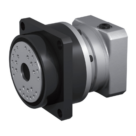
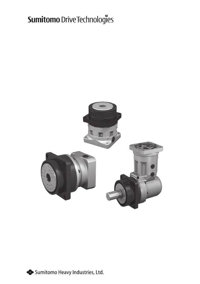
Sumitomo Drive Technologies Smartris User manual

Maintenance Manual No.DM1801E-1
This product should be handled by only those who have been trained for the work.
Please read this manual carefully before use.
Deliver this manual to the customer who will actually use the product.
This instruction manual should be carefully stored.
smartris Gearmotor
<Note>

1
Introduction: Safety Precautions

1
Introduction: Safety Precautions
- Carefully read this maintenance manual and all accompanying documents before use (installation,
operation, maintenance, inspection, etc.). Please use this unit after thoroughly understanding the ma-
chine, information about safety, and all precautions for correct operation.
After reading, retain this manual for future reference.
- Pay close attention to the "DANGER" and "CAUTION" warnings regarding safety and proper use.
DANGER Improper handling may result in physical damage, serious personal injury and
/ or death.
CAUTION Improper handling may result in physical damage and/ or personal injury.
Matters described in CAUTION may lead to serious danger depending on the situation.
Be sure to observe important matters described herein.
DANGER
- Transport, installation, plumbing, wiring, operation, maintenance, and inspections should be per-
formed by trained technicians; otherwise, electric shock, injury, re, or damage to the equipment
may result.
- In the case of maintenance with disassembly of this device, contact the nearest authorized main-
tenance shop.
- When the unit is to be used for an elevator or lifter, install a safety protecting device on the eleva-
tor side to prevent it from falling; otherwise, personal injury or damage to the equipment due to
falling of hoisting equipment may occur.

2
Introduction: How to Refer to the Maintenance Manual, Table of Contents
3
1. Receiving Inspection
This is the maintenance manual for the smartris gearmotor unit.
For servo drive unit maintenance, see the smartris Servo Drive Unit Maintenance Manual (No. DM1802E).
Contents
Introduction: Safety Precautions ………………………………………………………………… 1
Introduction: Reading the Maintenance Manual, Table of Contents ………………………… 2
1. Receiving Inspection …………………………………………………………………………… 3
2. Storage …………………………………………………………………………………………… 5
3. Transport ………………………………………………………………………………………… 6
4. Installation ……………………………………………………………………………………… 7
5. Coupling with Other Machines ………………………………………………………………… 8
6. Wiring……………………………………………………………………………………………… 11
7. Operation ………………………………………………………………………………………… 12
8. Daily Inspection and Maintenance …………………………………………………………… 14
9. Troubleshooting ………………………………………………………………………………… 16
10. Construction Drawings ………………………………………………………………………… 18
11. Warranty ………………………………………………………………………………………… 20

2
Introduction: How to Refer to the Maintenance Manual, Table of Contents
3
1. Receiving Inspection
CAUTION
- Unpack the unit after verifying that it is positioned right side up; otherwise, injury may result.
- Verify that the unit received is the one you ordered. Installing the wrong unit may result In per-
sonal injury or equipment damage.
- Do not remove the nameplate.
Verify the items listed below upon receiving the product. If a nonconformity or problem is found, please
contact with your nearest agent, distributor, or sales oce.
[1] Does the information on the nameplate conform to what you ordered?
[2] Was any part broken during transport?
[3] Are all bolts and nuts tightened rmly?
1-1 Reading the Nameplates
When contacting the company, please provide [1]. Gearmotor nomenclature, [2]. Reduction ratio, and
[3]. Serial number.
MODEL
B.AMP
M.AMP
r/min
SERIAL No.
VOLTS
RATIO
MOTOR TYPE
OUTPUTRATING
RATING
B.TORQUE
FRAME
N・m
N・m
GEARMOTOR
SERVO
M/BTHERMAL
QR
code
AUT277G
A
M.RATING N・m
V
[1] Gearmotor nomen-
clature (see P4)
[2] Reduction ratio
- Motor nomenclature
- Motor characteristics
- Brake current value
[3] Serial number
- Motor frame size
Figure 1-1 Nameplate
- Brake torque
1-2 Lubrication Method
All smartris models use grease lubrication, which is included when the product is shipped from the fac-
tory. Please use this product as-is.

4
1. Receiving Inspection
5
2. Storage
1-3 Gearmotor Nomenclature
Symbol meanings are shown below. Please conrm that the nomenclature matches the order.
Model Symbol
C ALTAX NEO
Frame Size
5087E 5097E 5097P 5107P
Output Shaft Direction
H Horizontal Output Shaft
Reduction Ratio
Mounting Style
F Flange Mount
With or Without Brake
B With Brake
Motor Coupling
M Direct Coupling
Auxiliary Type
SV With Servo Motor
C H F M 5097E SV B 21

4
1. Receiving Inspection
5
2. Storage
If this product is not for immediate use, note the following points when storing it.
2-1 Storage Location
Store the product in the clean and dry indoor.
Do not store outdoors. Store in a location that is free of moisture, dust, extreme temperature changes,
corrosive gases, etc.
2-2 Storage Period
- The storage period should be less than one year.
- If the equipment is to be exported or stored for at least one year, special rust prevention measures must
be taken.
- Exported items require rust prevention measures, so please contact us.
- Standard rust prevention specications
External rust prevention Rust prevention oil is applied before shipping from the factory. Conrm
rust prevention conditions every six months after delivery and reapply
rust prevention measures as needed.
Internal rust prevention Store in a general factory or warehouse in an environment free of
moisture, dust, extreme temperature changes, corrosive gases, etc.
2-3 Using after Storage
- Oil seals are aected by temperature, ultraviolet light and other ambient conditions and can easily de-
grade. After long storage periods, inspect before operation, and replace any degraded seals with new
seals.
- At startup, check whether there are not unusual noises, vibrations, temperature rises, or other symptoms.
For motor, conrm that brake works properly. If any abnormalities are found, immediately contact the
nearest authorized maintenance shop.

6
3. Transport
7
4. Installation
DANGER
- Do not step under the unit suspended by a crane or other machines for transport; otherwise,
injury or death may result.
CAUTION
- Be careful not to drop the product during transport.
- Before hoisting, check the weight with the nameplate, crate, outline drawing, catalog, etc. Never
hoist the product that exceeds load capacity of the crane or other mechanism being used to lift
it; otherwise, injury or damage to the equipment and/or lifting device may occur.
- Use a suitable hoisting attachment, check to ensure that the eye bolts and nuts are not loose, and
then hoist the product.

6
3. Transport
7
4. Installation
DANGER
- Do not use the unit in an explosive atmosphere; otherwise, explosion, ignition, an electric shock,
injury, a re, or damage to the equipment may occur.
CAUTION
- Do not use the products for purposes other than those shown on the nameplate or in the manu-
facturing specications; otherwise, electric shock, personal injury, or damage to the equipment
may result.
- Do not place inammables around the product; otherwise, a re may occur.
- Do not place any objects that hinder ventilation around the product; otherwise, cooling eects
may be reduced, leading to a re hazard due to excessive heating.
- Do not step on or hang from the product; otherwise, injury or damage to the equipment may
result.
- When the unit is used in equipment that is sensitive to oil contamination, install an oil pan or
other such device to prevent grease leakage due to failure or wear; otherwise, grease leakage
may damage products.
- This product is driving device for automated guided vehicles (AGVs). It cannot be used in other
applications, such as driving device for elevators.
4-1 Location of Installation
Ambient temperature: −10 to +40°C
Ambient humidity: 85% max.
Altitude: 1000m max.
Ambient atmosphere - There should be no corrosive gas, explosive gas, or steam.
- The location should be well ventilated and free from dust.
Installation locations - Indoor areas with little dust (IP54 protection class, dust and splash proof)
- Vibration: 1G max.
- Mounting In conditions other than above requires optional specications. Please consult with us.
- Drives fabricated according to special specications, such as outdoor use types, can be used in the
specied mounting environments. However, concerning the connector to the machine used, imple-
ment measures based on the Mounting environment.
- Mount In a location that enables easy operation, such as inspection and maintenance.
- Mount in a suciently rigid casing.
4-2 Mounting Angle
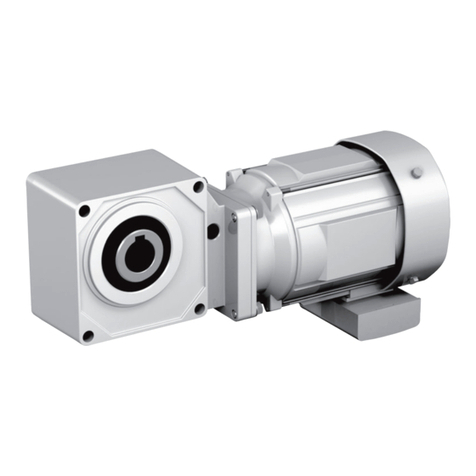
Possible mounting angle for this product is only horizontal output shaft direction. Please do not use this
drive at any other shaft mounting angle.
Note, however, that if the product is manufactured according to your designated mounting angle, do
not use it at any other mounting angle.
8
5. Coupling with Other Machines
9
5. Coupling with Other Machines
CAUTION
- Conrm the rotation direction before coupling with the AGV main unit. Dierence in the rotation
direction may cause injury or damage to the equipment.
- Pay attention to the direct coupling accuracy when the unit is directly coupled with the AGV main
unit. Securely fasten tightening bolts before operation; otherwise, injury or damage to the equip-
ment may result due to scattering fragments.
5-1 Conrming Rotation Direction
When connecting output power supply (U, V, W) for the servo drive unit to the servo motor terminals
(U, V, W), the motor shaft rotates counterclockwise as seen from the anti-load side. (Reverse rotation of
general motors for Japan’s domestic market.)
Note that changing the phase sequence of the U, V, W wiring will prevent this product from operating
and may cause malfunctions. Always perform wiring in the designated phase sequence.
The output rotation direction should be in the direction of the arrow in the gure below.
The rotational direction may dier in the case of special specications, so conrm the manufacturing
specications.
Table 5-1 Output Shaft Rotation Direction
Type ECO (Gear Output Shaft Rotation) PRO (Ring Gear Housing Rotation)
Size S, M M, L
Frame Size 5087E, 5097E 5097P, 5107P
Output shaft rota-
tion direction
(as seen from the
load side)
Reverse rotation with respect to the input
rotational direction.
Same rotation with respect to the input
rotational direction.

8
5. Coupling with Other Machines
9
5. Coupling with Other Machines
5-2 Installation Procedure
■ECO Type
[1] Mounting Gearmotor
[2] Mounting Wheel
Mounting part
Mounting part
Wheel
Wheel
B
A
AC
Mounting part
Mounting part
Wheel
Wheel
B
A
AC
- Fasten the bolt on the AGV main unit (or mounting
part). (Spigot Ⓐ)
Size S M
Frame Size 5087E 5097E
Spigot A Ø110 f8 Ø138 f8
Tightening
Bolt
Q’ty 4 8
Size M8 M8
Strengthening
Classication 8.8 8.8
Tightening
Torque
N•m
18.5 18.5
- Apply molybdenum disulde grease (an anti-fretting
agent) to spigot Ⓑ.
- Fix the wheel with a bolt. (Spigot Ⓑ)
Size S M
Frame Size 5087E 5097E
Spigot B Ø25H7 Ø25H7
Tightening
Bolt
Q’ty 10 8
Size M6 M8
Strengthening
Classication 12.9 12.9
Tightening
Torque
N•m
17.0 41.5
Notes: 1. The tightening bolt is not included and must be provided by the customer.
2. Please ensure that the tightening bolt is tightened with the designated tightening torque. To pre-
vent loosening, apply an adhesive to bolts (Loctite 262, etc.) or use a Belleville washer (JIS B 1251,
class 2).
3. ECO and PRO types use dierent materials for mounting on the AGV main unit. Please note the
strengthening classication and tightening torque for used bolts.

10
5. Coupling with Other Machines
11
6. Wiring
■PRO Type
[1] Mounting Wheel
Mounting part
Mounting part
Wheel
Wheel
B
A
AC
Mounting part
Mounting part
Wheel
Wheel
B
A
AC
-
Apply an appropriate amount of molybdenum disulde
(an anti-fretting agent) to the circumference of spigot
Ⓐ(there is no need for application to the end face).
-
Mount an O-ring at O-ring groove Ⓒ. (The O-ring is
attached to prevent molybdenum disulde applied to
the spigot part from leaking outside through any gaps.)
- Fix the wheel with a bolt. (Spigot Ⓐ)
Size M L
Frame Size 5097P 5107P
Spigot A Ø145 h7 Ø182 h7
Tightening
Bolt
Q’ty 12 12
Size M5 M6
Strengthening
Classication 10.9 10.9
Tightening
Torque
N•m
8.0 13.6
O-ring
(nitrile
rubber)
Designation AS568-261 G-140
Thickness ×
Inner
diameter
3.53×171.04 3.1×139.4
[2] Mounting Gearmotor
-
Fasten the bolt on the AGV main unit
(or mounting part).
Size M L
Frame Size 5097P 5107P
Tightening
Bolt
Q’ty 4 4
Size M10 M12
Strengthening
Classication 8.8 8.8
Tightening
Torque
N•m
46.0 79.0
Notes: 1. The tightening bolt and O-ring are not included and must be provided by the customer.
2. Please ensure that the tightening bolt is tightened with the designated tightening torque.
To prevent loosening, apply an adhesive to bolts (Loctite 262, etc.) or use a Belleville washer (JIS
B1251, class 2).
3. ECO and PRO types use dierent materials for mounting on the AGV main unit. Please note the
strengthening classication and tightening torque for used bolts.

10
5. Coupling with Other Machines
11
6. Wiring
For wiring details, see the smartris Servo Drive Unit Maintenance Manual (No. DM1802E).
DANGER
- Do not handle the unit when cables are energized. Be sure to turn o the power when working
on the unit; otherwise, electric shock may result.
- Follow instructions in the Maintenance Manual when connecting power cables; otherwise, elec-
tric shock or re may result.
- Do not forcibly bend, pull, or clamp the power cable and lead wires; otherwise, electric shock or
re may result.
- Correctly ground the grounding bolt; otherwise, electric shock may result.
CAUTION
- When wiring, follow the facility's regulations and electrical codes, in order to prevent burning,
electric shock, injury, and re.
- The motor is not equipped with a protection device. However, it is compulsory to install an over-
load protector according to facility electrical codes. It is recommended to install other protective
devices (earth leakage breaker, etc.), in addition to an overload protector to prevent burning,
electric shock, injury, and re.
- Do not touch the terminals when measuring insulation resistance; otherwise, electric shock may
result.
- Changing the phase sequence of the U, V, W wiring will prevent this product from operating and
may cause malfunctions. Always perform wiring in the designated phase sequence.
- For motor, do not energize the brake coil when the motor is stopped. Otherwise coil burnout re
may result. Also, mistaken wiring could damage the rectier.
- Long cables cause large voltage drops. Select cables with appropriate diameter so that the volt-
age drop will not be greater than 2%.

12
7. Operation
13
7. Operation
DANGER
- Do not approach or touch rotating parts (output shaft, etc.) during operation; otherwise loose
clothing may become caught in these rotating parts and cause serious injury or death.
- When the power supply is interrupted, be sure to turn o the power switch. Unexpected resump-
tion of power may cause electric shock, personal injury, or damage to the equipment.
CAUTION
- Do not put ngers or foreign objects into the opening of the product; otherwise, electric shock,
injury, re, or damage to the equipment may result.
- The product becomes very hot during operation. Be careful not to touch with hands or body.
Otherwise, burns may result.
- If any abnormality occurs during operation, stop operation immediately; otherwise, electric
shock, personal injury, or re may result.
- Do not operate the unit in excess of the load rating; otherwise, injury or damage to the equip-
ment may result.

12
7. Operation
13
7. Operation
7-1 Items to Check Before Operation
After installation and wiring are completed, check the following items before operating.
- Is the wiring correct?
- Is the unit properly coupled with the AGV main unit?
- Are Mounting bolts tightened rmly?
- Is the rotation direction as required?
Upon completing the above checks, run the motor under no load, and gradually apply a load to it. At
this time, check the items in Table 7-1.
7-2 Items to Check During Operation
Table 7-1 Items to Check During Operation
Does abnormal sound or vibration
generate?
- Is the housing deformed because the installation surface is not
at?
- Is Insucient rigidity of the installation base generating reso-
nance?
- Is the shaft center-aligned with the AGV main unit?
- Is vibration from the AGV main unit transmitted to this prod-
uct?
Is the surface temperature abnormally
high?
- Does the voltage rise or drop substantially?
- Is the ambient temperature too high?
- Does the current owing to the product exceed the rated cur-
rent shown on the nameplate?
If any abnormalities are found, immediately stop operation and contact the nearest authorized mainte-
nance shop.
7-3 Brake
This product has a built-in precision retention brake (PM brake or spring brake) for use when parking.
The brake is assembled in an appropriate state at the time of shipping from the factory; never disas-
semble it.
The brake is for maintaining location when parking. Never externally rotate or move the carriage while
braking action or with brake applied; otherwise, the brake may be damaged.

14
8. Daily Inspection and Maintenance
15
8. Daily Inspection and Maintenance
DANGER
- Do not handle the unit when cables are energized. Be sure to turn o the power when working
on the unit; otherwise, electric shock may result.
- Do not approach or touch any rotating parts (output shaft, etc.) while conducting maintenance
with operation or the inspection of the unit, loose clothing may become caught in these rotating
parts and cause serious injury or death.
CAUTION
- Do not put ngers or foreign objects into the opening of the product; otherwise, electric shock,
injury, re, or damage to the equipment may result.
- The product becomes very hot during operation. Do not touch the product with bare hands.
Otherwise, burns may result.
- Do not touch the terminals when measuring insulation resistance; otherwise, electric shock may
result.
- Do not operate the unit without a safety cover (removed during inspection) to shield rotating
parts; otherwise loose clothing may became caught in these rotating parts and cause serious
injury or death.
- Promptly observe and repair any abnormalities during operation according to instructions in this
maintenance manual. Do not operate until the cause of the abnormality is understood, and the
abnormality is repaired.
- Do not operate damaged product; otherwise, injury, re, or damage to the equipment may result.
- We cannot assume any responsibility for damage or injury resulting from an unauthorized modi-
cation by a customer, as it is outside the scope of the warranty.
- Dispose of the product or lubricating oil as general industrial waste.
- This product has a built-in precision retention brake (PM brake or spring brake) for use when
parking. The brake is assembled in an appropriate state at the time of shipping from the factory;
never disassemble it.

14
8. Daily Inspection and Maintenance
15
8. Daily Inspection and Maintenance
8-1 Daily Inspection
Make certain to carry out daily inspection in accordance with Table 8-1. Lack of inspections is a source
of trouble.
Table 8-1 Daily Inspection
Inspection Item Inspection Detail
Current value Is the current no greater than the rated value shown on the nameplate?
Noise Are there unusual noises, or are there extreme changes in the noises?
Vibration Is there abnormally large vibration? Are there extreme changes?
Surface temperature
Is surface temperature unusually high? Are there extreme changes?
Temperature rises during operation will differ according to model and type. How-
ever, in case the difference between the gear unit surface temperature and the
environment temperature is approximately
40°C, there is no particular trouble
if uctuation is slight.
Grease leaks Is grease leaking from the gear unit? Are the oil seal sliding surfaces corroded?
Mounting bolts Are the mounting bolts loose?
- If any problems are found in a daily inspection, follow "9. Troubleshooting" (on P16 and 17) to take ap-
propriate actions. If these actions do not solve the issue, immediately contact the nearest authorized
maintenance shop.
8-2 Main Unit Maintenance
- Because the gear unit is lled with long-lasting grease, it can be used for long time without replenishing
the grease, but maintenance with disassembly after usage for approximately 20,000 hours or 3 to 5 years
will further extend the product lifetime.
Contact the nearest authorized maintenance shop regarding maintenance with disassembly.
- Oil seals have a lifetime. During long use, natural degradation and frictional wear will reduce eective-
ness. Product operating conditions and ambient environment will cause lifetime to widely vary. Given
normal operation (uniform load, running 10 hours per day, normal temperature) as a guideline, it is rec-
ommended to change them every 1 to 3 years. If the sliding surfaces of oil seals show signs of wear or
corrosion, replace them with new ones. The sliding surface of an oil seal is made of carbon steel, so in
order to prevent rust forming on it, if there are parts of the oil seal that are exposed to the outside, periodi-
cally take steps to prevent rusting by coating the oil seal with rust preventive oil.
Contact the nearest authorized maintenance shop regarding oil seal replacements.
- If stop and start are frequent, mounting bolts (or nuts) may come loose. Periodically check for looseness
as this is a source of miss-alignment, grease leakages, and load unbalance.

16
9. Troubleshooting
17
9. Troubleshooting
If any abnormal condition occurs, refer to Table 9-1, 9-2 and promptly take appropriate measures. If
these actions do not solve the issue, immediately contact the nearest authorized maintenance shop.
Table 9-1 Troubleshooting
Problem Cause Correction
The motor will not operate under no load
Power failure
Conrm battery and other power supplies.
Defective electric circuit Check the circuit.
Blown fuse Replace the fuse.
Protective device operates Fix the problem and re-operate.
Load locking Check the load and safety device.
Poor switch contact Adjust the contact unit.
Motor stator coil disconnect
Confer with authorized maintenance shop.
Bearing damage
Confer with authorized maintenance shop.
The motor rotates with no load, but the
output shaft and frame do not rotate
Damage to gear unit due to overloading
of gears, etc.
Confer with authorized maintenance shop.
The slow speed shaft rotates with no load
When a load is applied
The switch overheats Insucient switch capacity Replace with a specied switch.
Overload Decrease the load to the specied value.
Fuse tripping Insucient fuse capacity Replace with a specied switch.
Overload Decrease the load to the specied value.
The speed will not increase
and the motor is overheating.
Voltage drop
Conrm battery and other power supplies.
Overload Decrease the load to the specied value.
Short-circuited motor stator coil
Confer with authorized maintenance shop.
It stops. Bearing burnout
Confer with authorized maintenance shop.
Poor adjustment of protection device Adjust the protection device.
The motor runs in the reverse di-
rection. Wiring error Change the connection.
Fuse tripping The lead wire is short-circuited
Confer with authorized maintenance shop.
Poor contact between motor and starter Make complete connection.
Excessive temperature rise
Overload Decrease the load to the specied value.
Voltage drop or rise
Conrm battery and other power supplies.
The ambient temperature is high Improve the ventilation method.
Damaged bearing
Confer with authorized maintenance shop.
Abnormal wear of reducer parts due to
overload. etc.
Confer with authorized maintenance shop.
Grease leakage
Oil and fat blot or drip from the oil
seal.
Grease applied to the oil seal seeps out
at rst.
Wipe o around the oil seal, and observe.
Grease leaks from the oil seal. Damaged oil seal or damaged output
shaft (or frame)
Confer with authorized maintenance shop.
Leakage of grease from the mating
faces of the frame, cover, etc. Loose fastener bolts Tighten fastener bolts correctly.
Grease leaks into motor. Damaged oil seal
Confer with authorized maintenance shop.
Abnormal sound
Excessive vibration
Dust and foreign matter in bearings, or
damaged bearings
Confer with authorized maintenance shop.
Reducer parts grinding on foreign matter
Confer with authorized maintenance shop.
Reducer parts are damaged
Confer with authorized maintenance shop.
Warping of casing because the installa-
tion surface is not at
Make the installation base at or make
adjustment by using liners, etc.
Resonance due to insucient rigidity of
the installation base
Reinforce the installation base to in-
crease rigidity.
Nonalignment of the shaft center with
the AGV main unit Align the center of axle.
Transmission of vibration from the AGV
main unit
Individually operate the product to
check the source of the sound.

16
9. Troubleshooting
17
9. Troubleshooting
Table 9-2 Troubleshooting
Problem Cause Correction
Abnormal motor sounds Foreign objects have entered
Confer with authorized maintenance shop.
Bearing damage
Confer with authorized maintenance shop.
Servo tripping
Overcurrent shut-o Sudden speed changes Increase the time for speed changes.
Extreme load uctuation Decrease load uctuation.
Overcurrent due to ground fault Ground fault on output side Take measures to prevent ground fault.
Direct current overcurrent Short on output side Take measures to prevent short.
Inspect wiring.
Regenerative overvoltage shut-o
Sudden speed reduction Increase the time for speed reduction.
Decrease brake frequency.
Thermal operation Overload Decrease the load to the specied value.

18
10. Construction Drawings
19
10. Construction Drawings
10-1 Construction Drawing (ECO Type)
Figure 10-1 ECO Type (E.g.: CHFM-5097E-SV-B-21)
Table 10-1 Gear Motor Principal Parts
Part
Number
Part Name
Part
Number
Part Name
Part
Number
Part Name
Part
Number
Part Name
1 Output Shaft 7 Spacer Ring 13 Joint Spline 19 Carrier Pin Pipe
2 Oil Seal 8 Slow Speed Shaft
Pin 14 Intermediary
Flange 20 Cycloid Disc
3 Bearing 9 Frame 15 Carrier 21 Bearing
4 Cover 10 Ring Gear Housing
Pin 16 Central Shaft 22 Eccentric
5 Bearing 11 Bearing 17 O-ring 23 (Wheel)
6 Distancing Piece 12 Motor 18 Carrier Pin
Note: Wheel supplied by customer.
①
㉓ ㉒ ⑰ ㉑ ⑳ ⑲ ⑱ ⑰ ⑯ ⑮ ⑭ ⑬
②③ ④ ⑤⑥⑦⑧⑨ ⑩ ⑪ ③ ⑫
Table of contents
Other Sumitomo Drive Technologies Engine manuals

Sumitomo Drive Technologies
Sumitomo Drive Technologies IB Series User manual

Sumitomo Drive Technologies
Sumitomo Drive Technologies RHYTAX User manual

Sumitomo Drive Technologies
Sumitomo Drive Technologies HYPONIC DRIVE User manual

Sumitomo Drive Technologies
Sumitomo Drive Technologies IB Series User manual