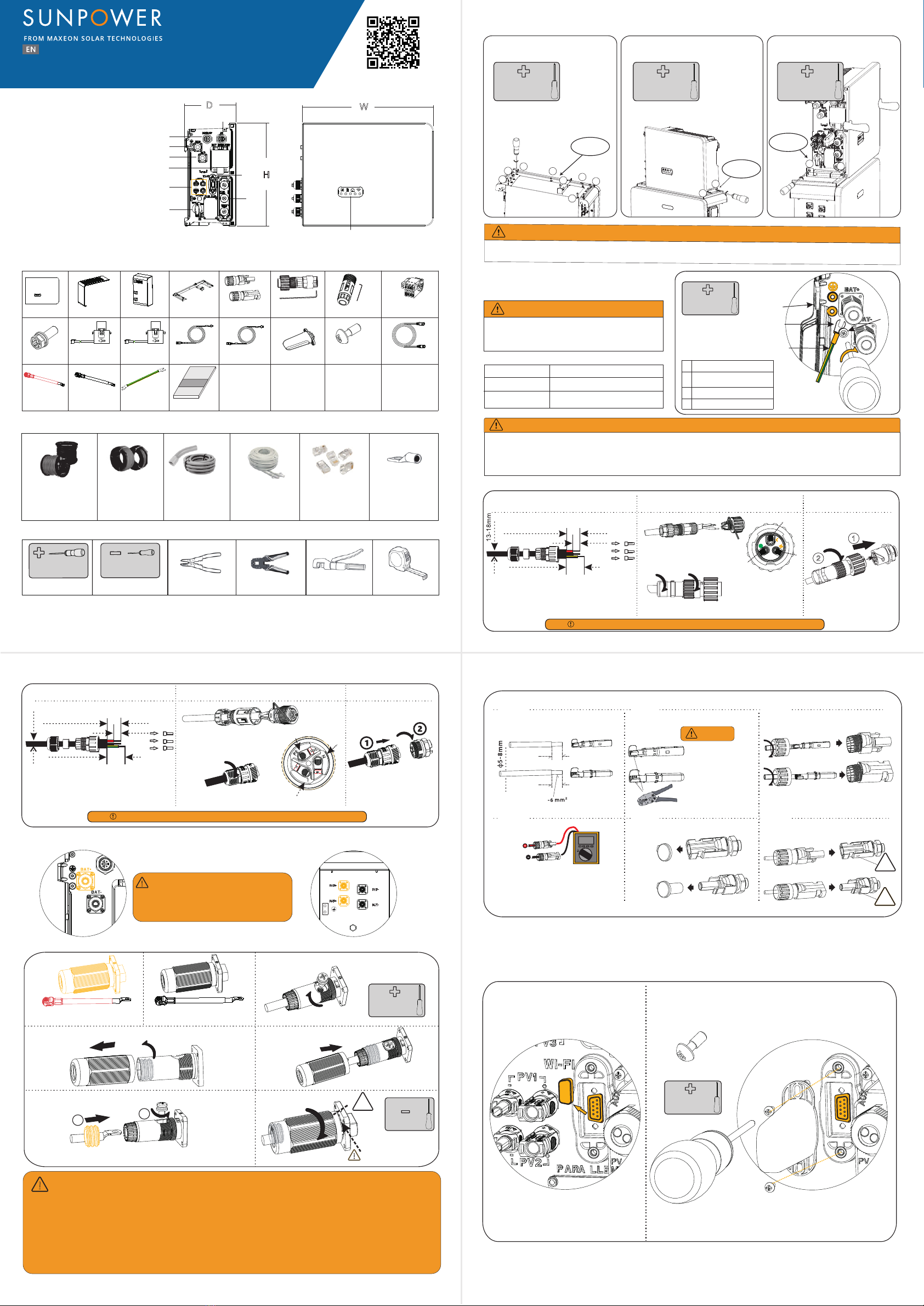
1.0 Product Overview
(1) Grid connector
(2) Backup connector
(3) BAT +
(4) BAT -
(5) ery circuit breaker
(6) PV connectors
(7) PV switch
(8) Wi-Fi port
(9)
(10) LED display
Dimension: W×H×D=483×380×190mm
for SunPower Reserve
(1)
(2)
(3)
(4)
(5)
(6)
(7)
(8)
(9)
(10)
You must protect each inverter with an
individual AC circuit breaker in order to ensure
that the inverter can be disconnected safely
(X2)
(X16) (X1
Grid-CT Grid-CT CablePV-CT PV-CT Cable
)
(X1) (X1) (X1)
(X1)
(X1)
(X1)
(X1)
(X1) (X1)
(X1)
(X1) (X1) (X1)
(X1)(X1) (X2)
Approx. 10-12mm
For “L”and “N”
7-8mm
9-12mm
Approx. 18mm for PE
L
N
PE
(X1)
click
click
7mm
7mm
PV1-F/UL-ZKLA/USE2
PV1-F/UL-ZKLA/USE2
2.6-2.9 N·m
4
P 2×150mm
1.6Nm
H
×2
QUICK INSTALLATION GUIDE
MODEL: RESERVE-INV-1-P5-L1-INT
click
1.2×75mm
P 2×150mm
4.5-5Nm
H
21
1. S
2. Connect the BAT -
the BAT + wire (Red)
!
01 02
03 04
φ
!
H
DW
PH2×150mm 1.2×75mm
2.1 Scope of Delivery
2.2 Addional Materials Required for Installaon
2.3 Installaon Tools
3.2 Installing the Inverter
3.1 Before installing the inverter ensure that the baery is properly installed. For more details refer
to Baery Quick Installaon Manual or Safety and Installaon Instrucons.
4.1 Installing the PE cable
DANGER
4.2 Connecng the Grid Power Cable
4.3 Connecng the AC Backup Power Cable
4.4 Connecng the BAT Power Cable
4.5 Connecng the PV Power Cable
548268 Rev. A
P 2×150mm
2.5Nm
H
16
78
2
43
5
Step 1:
Installing the base of the inverter
Support sheet
metal
P 2×150mm
2.5Nm
H
11 12
Step 3:
P 2×150mm
2.5Nm
H
9
10
Step 2:
Lock right screws
Lock right screw
Grid side
Backup side
32A/40A
32A
Step 1 Step 2 Step 3
copper cable
²
threaded sleeve and swivel nut together
and PE into corresponding terminals
(torque 1.5
±0.1N·m).
Plug the connector into the
Step 1
Step 2
Step 3
Step 4
Step 5
Inverter Side BAT Side
BAT Power + and red Cable
BAT Power - and black Cable
screwdriver when unscrew the
swivel nut
Step 1 Step 2 Step 3
Step 4 Step 5 Step 6
Assemble the MC4 cable ends
Crimp pliers to
cable ends
Assemble the connectors
Please check if the cables are securely
installed by pulling outwards
Check the open-circuit voltage is less
than 580V
Remove the waterproof caps from
PV connectors
please seal it with the cap
hear an audible click.
5.1 Wi-Fi module Connecon
NOTICE
Phillips Screwdriver Flat-Head Screwdriver Wire Stripper Network Wire Clamp Crimping Plier Tape Measure
1
23
PH2×150mm
2.5Nm
4
Housing
conductor
M5×12 PH2 head screw
PE Cable4
3
2
1
Step 2
1
2
Align the AC connector
Plug the AC connector
into the jack and screw tight
Step 1 Step 3
Assemble the locking cap, threaded sleeve
and swivel nut together.
Approx. 60mm
For “L”and “N”
7-9mm
Approx. 65mm for PE
Insert the crimped conductors, L, N
and PE into corresponding terminals
and tighten the screws
(torque 1.2±0.1N·m).
L
N
PE
PE
Three-core (L, N and PE) outdoor
copper cable
Conductor cross-section: 6-8 mm²
φ
•
energy release.
•
•
!
Grounding
BAT+ Power
Connector
BAT- Power
Connector
_
_
_
_
_
_
DC CablePV1-F
Conductor cross-
section4-6 mm²
Conduits
Ethernet Cables
Cat5eTP
V-resistant for
outdoor use
RJ45 Plugs PE Terminal
6-8 mm²Grid Cable
²
Three-core outdoor
copper cable
DANGER


