The above values are from NEC Table 310.15(B)16 for copper cables rated at 75°C (167°F),
operating at an ambient temperature of no more than 30°C (86°F). Lengths in excess of 6 feet
(1829 mm) may require heavier gauge cable to avoid excess voltage drop in undersized wiring.
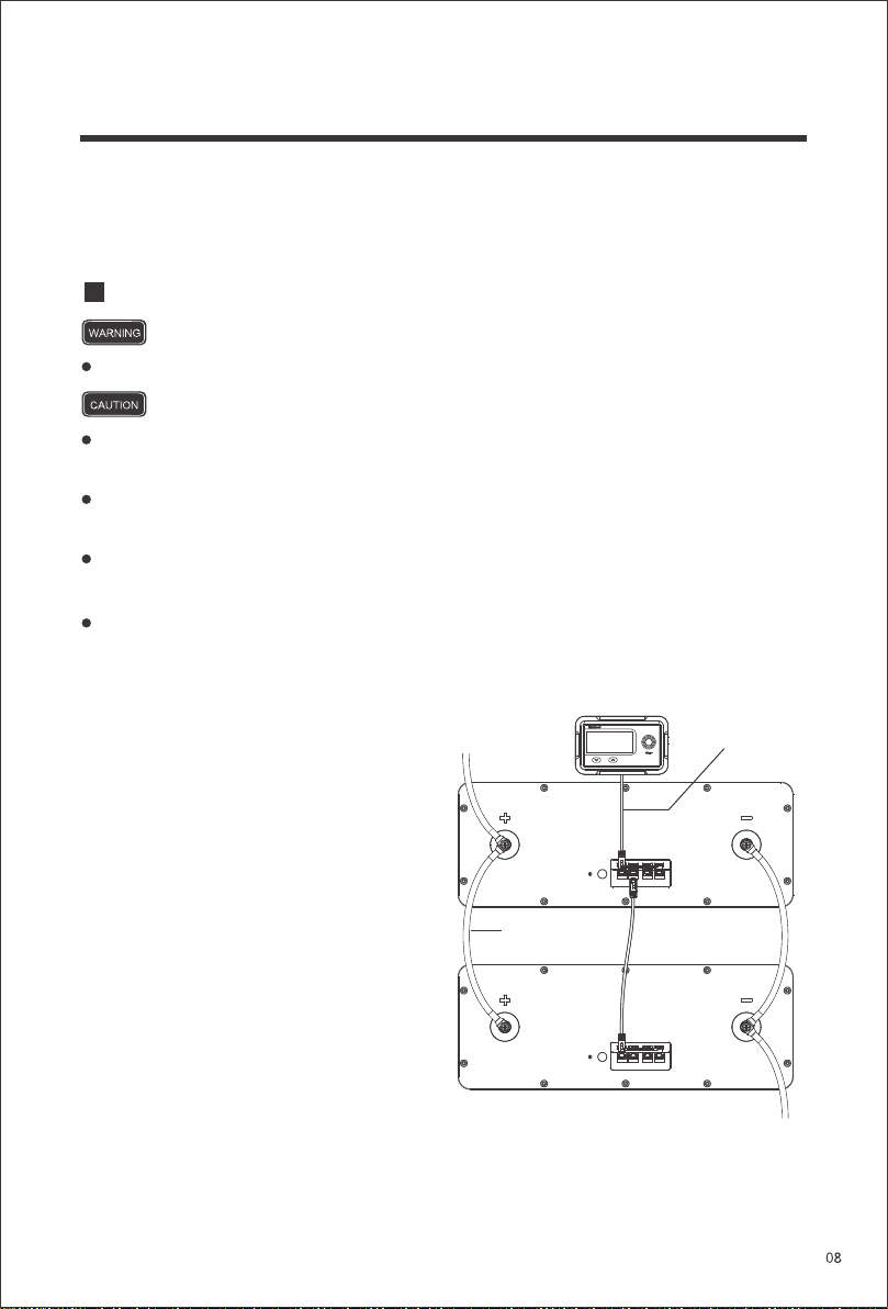
To string multiple batteries in parallel, first
connect the Positive Terminals of the
batteries to each other. Then, connect the
Negative Terminals of the batteries to
each other. Finally, connect the Positive
Terminal of the first battery and the
Negative Terminals of the last battery to
the system. This type of arrangement is
used to increase the overall battery capac-
ity while keeping the voltage the same.
DO NOT string batteries in series. Doing so can cause catastrophic failure.
DO NOT string batteries with different chemistries, brands, models, rated capacities,
or nominal voltages in parallel.
Please avoid too high a voltage difference between paralleled batteries, despite the
auto-balancing function, to avoid triggering the over-current protection.
In parallel battery banks, the cables between each battery should be of equal length to
ensure that all batteries in the system can work equally together.
It is not recommended to connect more than 8 batteries in parallel if taking advantages of
the auto-balancing function.
Connecting Batteries in Banks
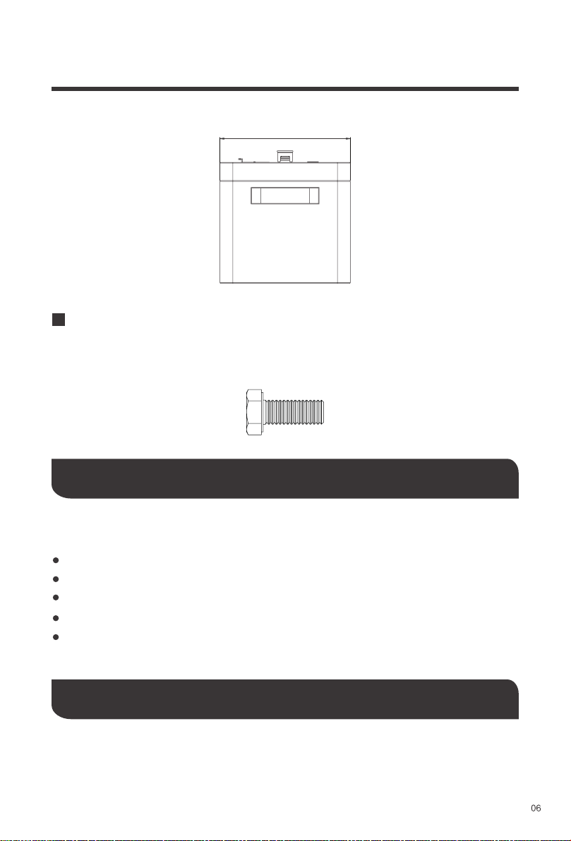
Copper Cable
Communication
Cable
To enable the communication between
paralleled batteries for the proper operation
of the Renogy Monitoring Screen or the
Renogy Bluetooth Module, connect the
RS485 LINK Communication Ports of the
former batteries to the RS485 UP Commu-
nication Ports of the latter ones using CAT5
(or above) Ethernet straight through cables
(not included). The Renogy Monitoring Screen or the Renogy Bluetooth Module should be
connected tothe RS485 UP Communication Port of the first battery.