Sun Power RESERVE-BAT-1-DC-10.1-INT User manual

SunPower Reserve Quick Installation Guide
Home energy storage system (RESERVE-BAT-1-DC-10.1-INT)
548267 Revision B - Jun 2023
1.0 Transport
2.2 Dimensions
2.0 Product Overview
Risk of injury when lifting the battery as the battery weighs 90 kg. There is risk of injury if the battery is lifted
incorrectly while being transported.
Transport the battery always as described below.
Handle with care, choose the corresponding handling method according to the weight, and pay attention to safety.
For additional batteries, keep a minimum spacing of 300mm. Do not stack batteries.
During transportation, please follow these guidelines:
1. The original packaging should be used for transportation.
2. Handle with care, choose the corresponding handling method according to the weight, and pay attention to safety.
3. Duringtransportation,pleasekeepthepackagingawayfromdangeroussourcesandtakewaterproofingmeasures.
4. Secure the packaging during transportation.
(1)
(2) (4) (5)
(8)
(6)
(7)
(6)
(*)
(3)
Position Description
1 Battery Start Button
2 Battery Circuit Breaker
3 Battery LED Display
4 Battery+ Power Connector
5 Battery- Power Connector
6 Grounding terminal
7 BMS COM (1)
8 BMS COM (2) (with terminal resistor)
2.1 LED Display
The three LED indicators on the front cover provide information about the State of Change (SOC) operational status of the battery.
State of Charge (SoC) Description
SOC≤10%
10%<SOC≤30%
30%<SOC≤50%
50%<SOC≤60%
60%<SOC≤90%
90%<SOC≤100%
Symbol Description
WhiteLEDsash
White LED on
LEDsareo
610mm
829mm
250mm
212mm
≥300mm ≥300mm ≥300mm
≥300mm≥300mm≥300mm≥300mm ≥300mm
12
6
2.3 Scope of Delivery
2.4 Mounting Location
BATTERY (RESERVE-BAT-1-DC-10.1-INT)
Battery Pack (x1) Left Side Plate (x1) Right Side Plate (x1) Wall bracket (x1) M5x12 (x3)
Limit Bracket (x2) Plastic set screws (M5-L8)
(x12)
Plastic Blockage (x4) Wall Anchor and Expansion
Screws (x4)
Y type Terminal Blocks (x2)
Battery Quick Installation
Guide (x1)
Grounding Cable (x1) Expansion Battery Positive
Power Cable (x1)
Expansion Battery Negative
Power Cable (x1)
90°
IP65 90kg
0°
-10°C
50°C
2.5 Installation
633mm
≥15mm ≥70mm
Ø10mm
1. 2. 0°
≥70mm
SW10
M6
Remove
Ø10mm
1
23
4
5
6 6 6
CAUTION
CAUTION
NEED MORE HELP?
Ifyouwouldliketocontactusdirectly,pleasevisitourocialwebsite:
https://sunpower.maxeon.com for more information.

• DONOTshortcircuitthebatteryterminals.First,completethe-terminalconnectionsbetweenbatteryand
inverter and then complete the + terminal connections.
• Touchingashortedbatteryconnectionmayresultinlethalinjuriesduetoelectricshockandmassiveenergy
release.
• Switchothebatterybreakerlocatedontherightsideofthebatterywhenmakingconnections.
• Pleaseconnectbothendsofonebatterypowercablecompletelybeforeconnectingthenextpowercableto
avoid short-circuiting of the positive and negative battery power cables.
2.6.2. Connecting to the Inverter Parts
2.6.3. Connecting more Batteries
BAT+
BAT-
Please remove the insulated sleeve
when connecting to the relative
battery terminal of the inventer.
1
1
7
8
9
3
3
6
2
2
4.1 Mounting the Screw Plugs
For better appearance, the top of the expanded battery needs to be locked with plastic screws and plastic covers.
Connect the cables between the batteries and route them from the rear side of the battery.
Disclaimer:
This Quick Installation Guide is not replacing Safety and Installation Instructions, it is a short introduction to the
product installation. The reference remains the Safety and Installation Instructions.
BAT -6
BAT +
BAT -
COM
GROUNDING
BAT -5 BAT -4 BAT -3
From BAT -1
to BAT -5
BAT -2 BAT -1
BAT -6 BAT -5 BAT -4 BAT -3 BAT -2 BAT -1
Remove
3.0 Commissioning
Switch ON:
Switch OFF:
Press 1 sec
OFF ON
1
2
2
3
4.0 Mounting the side Plates
3
4
5
√
1 2
*
*
*
*
*
*
*
*
**
≤3mm
M5x10 + PH2
2.5N.m
3. 4.
Position Designation
1 Housing
2 M5 terminal lug with protective conductor
3 M5x12 PH2 head screw
4 PE cable
2.6 Electrical Connection
2.6.1. Grounding
Refer to manual
1
2
3
4
PH2x150mm
2.5Nm
BAT+
BAT-
4
4
5
INV
BAT
1
2
3
4
1
2
3
M5x10 + PH2
2.5N.m
Press 5 sec
Lights are o
1
3
DANGER
CAUTION
CAUTION
NEED MORE HELP?
Ifyouwouldliketocontactusdirectly,pleasevisitourocialwebsite:
https://sunpower.maxeon.com for more information.
Safety and Installation Instructions for SunPower Reserve

SunPower Reserve Beknopte installatiehandleiding
Energieopslagsysteem voor thuisgebruik (RESERVE-BAT-1-DC-10.1-INT)
548267 revisie B - juni 2023
1.0 Transport
2.2 Afmetingen
2.0 Productoverzicht
Risico op letsel bij het optillen van de batterij omdat deze 90 kg weegt. Er is risico op letsel als de batterij tijdens het
transport verkeerd wordt getild.
Transporteer de batterij altijd zoals hieronder beschreven.
Ga voorzichtig te werk. Kies voor een methode die past bij het gewicht en neem de veiligheid in acht.
Houd bij additionele batterijen een minimale onderlinge afstand van 300 mm aan. Batterijen mogen niet worden
gestapeld.
Neem tijdens het transport de volgende richtlijnen in acht:
1. Voor het transport moet de originele verpakking worden gebruikt.
2. Ga voorzichtig te werk. Kies voor een methode die past bij het gewicht en neem de veiligheid in acht.
3. Houd de verpakking tijdens het transport uit de buurt van gevaarlijke bronnen en bescherm deze tegen water.
4. Zet de verpakking vast tijdens transport.
(1)
(2) (4) (5)
(8)
(6)
(7)
(6)
(*)
(3)
Positie Beschrijving
1 Batterijstartknop
2 Batterij-lastscheider
3 Led-display batterij
4 Voedingsconnector batterij+
5 Voedingsconnector batterij-
6 Aardklem
7 BMS COM (1)
8 BMS COM (2) (met eindweerstand)
2.1 Led-display
De drie ledlampjes aan de voorkant van de behuizing geven informatie over de ladingstatus van de batterij, ook wel SOC (State of
Charge) genoemd.
Ladingstatus (SOC) Beschrijving
SOC≤10%
10%<SOC≤30%
30%<SOC≤50%
50%<SOC≤60%
60%<SOC≤90%
90%<SOC≤100%
Symbool Beschrijving
Witte ledlampjes knipperen
Wit ledlampje brandt
Ledlampjes zijn uit
610 mm
829 mm
250 mm
212 mm
12
6
2.3 Omvang van de levering
2.4 Montageplaats
Batterij-eenheid (x1) Linkerzijplaat (x1) Rechterzijplaat (x1) Muurbeugel (x1) M5x12 (x3)
Eindsteun (x2) Kunststof stelschroeven
(M5-L8) (x12)
Kunststof blokkering (x4) Muuranker en
expansieschroeven (x4)
Klemmenblokken type
Y (x2)
Beknopte
installatiehandleiding voor
batterij (x1)
Aardingskabel (x1) Voedingskabel
uitbreidingsbatterij, plus (x1)
Voedingskabel
uitbreidingsbatterij, min (x1)
90°
IP65 90 kg
0°
-10 °C
50 °C
2.5 Installatie
633 mm
Ø 10 mm
1. 2. 0°
SW10
M6
Ø 10 mm
1
23
4
5
6 6 6
LET OP
LET OP
MEER HULP NODIG?
Wiljedirectcontactmetonsopnemen,bezoekdanonzeociëlewebsite:
https://sunpower.maxeon.com voor meer informatie.

• Sluit de batterijklemmen NIET kort. Bevestig eerst de - klemaansluitingen tussen batterij en omvormer en
vervolgens de + klemaansluitingen.
• Het aanraken van een kortgesloten batterijaansluiting kan leiden tot dodelijk letsel als gevolg van een
elektrische schok en het vrijkomen van grote hoeveelheden energie.
• Schakel de batterij-lastscheider aan de rechterkant van de batterij uit als je aansluitingen maakt.
• Sluit beide uiteinden van een batterijvoedingskabel volledig aan voordat je de volgende voedingskabel
aansluit om kortsluiting tussen de positieve en negatieve batterijvoedingskabels te voorkomen.
2.6.2. Aansluiten aan de omvormer
2.6.3. Meer batterijen aansluiten
BAT+
BAT-
Verwijder de geïsoleerde huls bij het
aansluitenopdedesbetreende
batterijklem van de omvormer.
1
1
7
8
9
3
3
6
2
2
Voor een fraaie afwerking moet de bovenkant van de extra batterij met kunststof schroeven en kunststof afdekkingen worden
afgewerkt.
Sluit de kabels tussen de batterijen aan en leg deze via de achterkant van de batterij.
Deze Beknopte installatiehandleiding is geen vervanging voor de veiligheids- en installatie-instructies, maar is
een korte inleiding tot de installatie van het product. Je moet nog steeds de veiligheids- en installatie-instructies
raadplegen.
BAT -6
BAT +
BAT -
COM
BAT -5 BAT -4 BAT -3
naar BAT -5
BAT -2 BAT -1
BAT -6 BAT -5 BAT -4 BAT -3 BAT -2 BAT -1
3.0 Inbedrijfstelling
Inschakelen:
Schakelaar UIT:
1
2
2
3
4.0 Montage van de zijplaten
3
4
5
√√
1 2
**
**
**
**
**
**
**
**
****
M5x10 + PH2
3. 4.
Positie Beschrijving
1 Behuizing
2 M5-kabelschoen, geïsoleerd
3 M5x12 PH2 kopschroef
4 Aardekabel
2.6 Elektrische aansluiting
2.6.1. Aarding
Raadpleeg de
handleiding
1
2
3
4
PH2x150 mm
BAT+
BAT-
4
4
5
BAT
1
2
3
4
1
2
3
M5x10 + PH2
Lampjes zijn uit
1
3
LET OP
LET OP
MEER HULP NODIG?
Wiljedirectcontactmetonsopnemen,bezoekdanonzeociëlewebsite:
https://sunpower.maxeon.com voor meer informatie.
Veiligheids- en installatie-instructies voor SunPower Reserve

SunPower Reserve Guide d’installation rapide
Système de stockage d’énergie domestique (RESERVE-BAT-1-DC-10.1-INT)
548267 RévisionB - Juin 2023
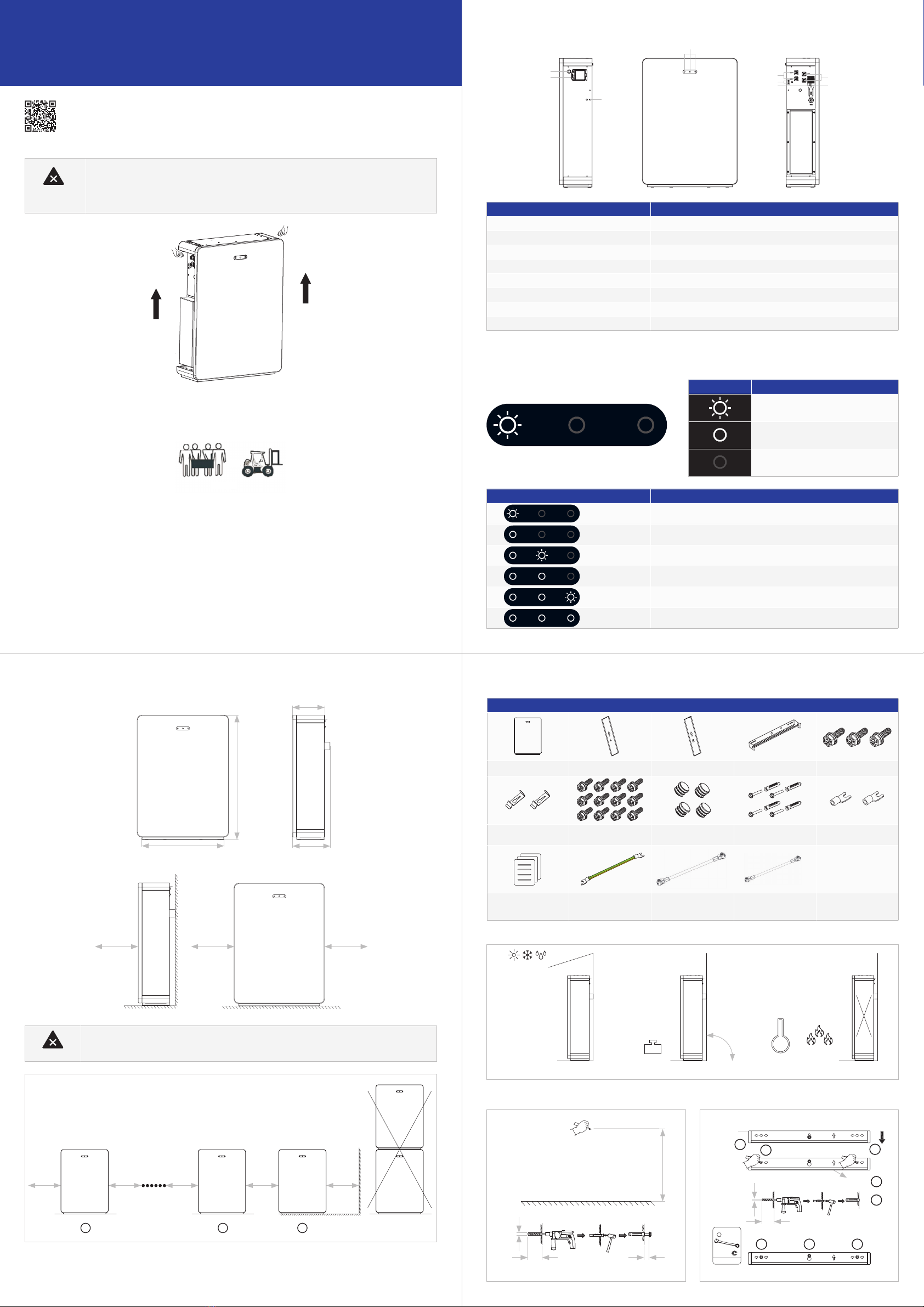
1.0 Transport
2.2 Dimensions
2.0 Aperçu du produit
Risque de blessure lors du levage de la batterie, qui pèse 90kg. Il y a un risque de blessure si la batterie est
soulevée de manière incorrecte pendant le transport.
Transportez toujours la batterie comme décrit ci-dessous.
Manipulez-la avec précaution, choisissez la méthode de manipulation appropriée en fonction du poids et veillez à
la sécurité.
Pour les batteries supplémentaires, respecter un espacement minimum de 300mm. Ne pas empiler les batteries.
Pendant le transport, veuillez respecter les consignes suivantes:
1. Utiliser l’emballage d’origine pour le transport.
2. À manipuler avec précaution, choisir la méthode de manipulation appropriée en fonction du poids et veiller à la sécurité.
3. Pendant le transport, tenir l’emballage à l’écart des sources de danger et prendre des mesures de protection contre l’eau.
4. Sécurisez l’emballage pendant le transport.
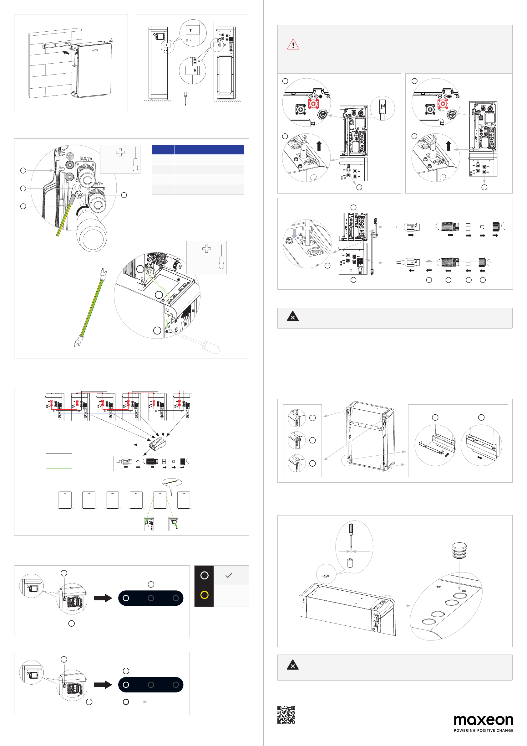
(1)
(2) (4) (5)
(8)
(6)
(7)
(6)
(*)
(3)
Position Description
1 Bouton de démarrage de la batterie
2 Disjoncteur de la batterie
3 Achage LED de la batterie
4 Connecteur d’alimentation Batterie+
5 Connecteur d’alimentation Batterie-
6 Borne de mise à la terre
7 BMS COM (1)
8 BMS COM (2) (avec résistance de terminaison)
2.1 écran LED
Les trois voyants LED situés sur la face avant fournissent des informations sur l’état de charge (SOC) de la batterie.
État de charge (SOC) Description
SOC≤10%
10%<SOC≤30%
30%<SOC≤50%
50%<SOC≤60%
60%<SOC≤90%
90%<SOC≤100%
Symbole Description
LED blanches clignotantes
LED blanche allumée
LED éteintes
12
6
2.3 Contenu de la livraison
2.4 Emplacement de montage
Bloc-batterie (x1) Plaque latérale gauche (x1) Plaque latérale droite (x1) Support mural (x1) M5x12 (x3)
Support de limite (x2) Vis de xation en plastique
(M5-L8) (x12)
Dispositif de blocage en
plastique (x4)
Vis d’ancrage et
d’expansion (x4)
Borniers de type Y (x2)
Guide d’installation rapide
de la batterie (x1)
Câble de mise à la terre (x1) Câble d’alimentation positif
de batterie supplémentaire
(x1)
Câble d’alimentation négatif
de batterie supplémentaire
(x1)
90
IP65
0°
2.5 Installation
1. 2. 0°
SW10
M6
Retirer
1
23
4
5
6 6 6
VOUS AVEZ BESOIN D’AIDE?
Si vous souhaitez nous contacter directement, veuillez consulter notre site Web ociel:
https://sunpower.maxeon.com pour plus d’informations.

• NE PAS court-circuiter les bornes de la batterie. Commencez par connecter les bornes - entre la batterie et
l’onduleur, puis connectez les bornes +.
• Le fait de toucher une connexion de batterie court-circuitée peut entraîner des blessures mortelles dues à un
choc électrique et à une libération massive d’énergie.
• Coupez le disjoncteur de la batterie situé sur le côté droit de la batterie lorsque vous eectuez des
connexions.
• Raccordez complètement les deux extrémités d’un des câbles d’alimentation de la batterie avant de
raccorder le câble d’alimentation suivant an d’éviter les courts-circuits entre les câbles positif et négatif de
la batterie.
2.6.2. Connexion aux pièces de l’onduleur
2.6.3. Connecter d’autres batteries
BAT+
BAT-
Veuillez retirer la gaine isolante lors
de la connexion à la borne relative
de la batterie de l’onduleur.
1
1
7
8
9
3
3
6
2
2
4.1 Montage des vis d’obturation
Pour une meilleure apparence, la partie supérieure de la batterie supplémentaire doit être xée à l’aide de vis et de bouchons
enplastique.
Connectez les câbles entre les batteries et acheminez-les depuis l’arrière de la batterie.
Ce guide d’installation rapide ne remplace pas les instructions de sécurité et d’installation, mais constitue une brève
introduction à l’installation du produit. La référence reste les Instructions de sécurité et d’installation.
BAT -6
BAT +
BAT -
COM
MISE À LA TERRE
BAT -5 BAT -4 BAT -3
De BAT -1
à BAT -5
BAT -2 BAT -1
BAT -6 BAT -5 BAT -4 BAT -3 BAT -2 BAT -1
Retirer
3.0 Mise en service
Mise sous tension:
Mise hors tension:
Appuyer 1 seconde
1
2
2
3
4.0 Montage des plaques latérales
3
4
5
√√
1 2
**
**
**
**
**
**
**
**
****
M5x10 + PH2
3. 4.
Position Désignation
1Logement
2 Cosse M5 avec conducteur de protection
3Vis à tête M5x12 PH2
4 Câble de mise à la terre
2.6 Raccordement électrique
2.6.1. Mise à la terre
Reportez-vous
aumanuel
1
2
3
4
BAT+
BAT-
4
4
5
BAT
1
2
3
4
1
2
3
M5x10 + PH2
Appuyer 5 secondes
Les voyants
sont éteints
1
3
VOUS AVEZ BESOIN D’AIDE?
Si vous souhaitez nous contacter directement, veuillez consulter notre site Web ociel:
https://sunpower.maxeon.com pour plus d’informations.
Instructions de sécurité et d’installation de SunPower Reserve

SunPower Reserve Guida rapida all'installazione
Sistema di accumulo domestico (RESERVE-BAT-1-DC-10.1-INT)
548267 Revisione B - Giugno 2023
1.0 Trasporto
2.2 Dimensioni
2.0 Panoramica del prodotto
Rischio di infortunio durante il sollevamento della batteria, che pesa 90 kg. Rischio di infortunio se la batteria
viene sollevata in modo non corretto durante il trasporto.
Trasportare sempre la batteria come descritto di seguito.
Maneggiare con cautela, scegliere il metodo di movimentazione più adeguato in base al peso e prestare
attenzione alla sicurezza.
Per batterie aggiuntive, mantenere una distanza minima di 300 mm. Non impilare le batterie.
Durante il trasporto, seguire le seguenti indicazioni.
1. Per il trasporto, utilizzare l'imballaggio originale.
2. Maneggiare con cautela, scegliere il metodo di movimentazione più adeguato in base al peso e prestare attenzione alla
sicurezza.
3. Durante il trasporto, tenere l'imballaggio lontano da fonti di pericolo e adottare misure per proteggerlo dall'acqua.
4. Fissare l'imballaggio durante il trasporto.
(1)
(2) (4) (5)
(8)
(6)
(7)
(6)
(*)
(3)
Posizione Descrizione
1 Pulsante di avvio batteria
2 Interruttore batteria
3 Display LED batteria
4 Connettore di alimentazione Batteria+
5 Connettore di alimentazione Batteria-
6 Morsetto di messa a terra
7 BMS COM (1)
8 BMS COM (2) (con resistore morsetto)
2.1 Display LED
Le tre spie LED sul coperchio anteriore forniscono informazioni sullo stato operativo dello stato di carica (SOC) della batteria.
Stato di carica (SoC) Descrizione
SOC≤10%
10%<SOC≤30%
30%<SOC≤50%
50%<SOC≤60%
60%<SOC≤90%
90%<SOC≤100%
Simbolo Descrizione
LED bianchi lampeggianti
LED bianco acceso
LED spenti
610 mm
829 mm
250 mm
212 mm
≥300 mm ≥300 mm ≥300 mm
≥300 mm≥300 mm≥300 mm≥300 mm ≥300 mm
12
6
2.3 In dotazione
2.4 Posizione di montaggio
BATTERIA (RESERVE-BAT-1-DC-10.1-INT)
Pacco batterie (x1) Piastra laterale sinistra (x1) Piastra laterale destra (x1) Staa a parete (x1) M5x12 (x3)
Staa di ne corsa (x2) Viti di ssaggio in plastica
(M5-L8) (x12)
Blocco in plastica (x4) Viti di ancoraggio e di
espansione (x4)
Morsettiere a Y (x2)
Guida rapida
all'installazione della
batteria (x1)
Cavo di messa a terra (x1) Cavo di alimentazione
positivo della batteria di
espansione (x1)
Cavo di alimentazione
negativo della batteria di
espansione (x1)
90°
IP65 90 kg
0°
-10 °C
50 °C
2.5 Installazione
633 mm
≥15 mm ≥70 mm
Ø10 mm
1. 2.
0°
≥70 mm
SW10
M6
Rimozione
Ø10 mm
1
23
4
5
6 6 6
ATTENZIONE
SERVE ULTERIORE AIUTO?
Per contattarci direttamente, visitare il nostro sito web uciale:
https://sunpower.maxeon.com .
ATTENZIONE

• NON cortocircuitare i morsetti della batteria. Completare prima i collegamenti dei morsetti - tra la
batteria e l'inverter, poi i collegamenti dei morsetti +.
• Toccare un collegamento della batteria in cortocircuito può provocare lesioni mortali dovute alla scarica
elettrica, oltre che causare il rilascio di una grande quantità di energia.
• Quando si eettuano i collegamenti, spegnere l'interruttore situato sul lato destro della batteria.
• Collegare completamente entrambe le estremità di uno dei cavi di alimentazione della batteria prima di
collegare il cavo di alimentazione successivo, per evitare di cortocircuitare i cavi di alimentazione negativo
e positivo.
2.6.2. Collegamento alle parti dell'inverter
2.6.3. Collegare altre batterie
BAT+
BAT-
Rimuovere la guaina di isolamento
durante il collegamento del relativo
morsetto della batteria dell'inverter.
1
1
7
8
9
3
3
6
2
2
4.1 Montaggio dei tappi a vite
Per migliorare l'aspetto estetico, chiudere la parte superiore della batteria espansa con viti di plastica e coperchi di plastica.
Collegare i cavi tra le batterie e instradarli dal lato posteriore della batteria.
Disclaimer:
Questa Guida rapida all'installazione non sostituisce le Istruzioni di sicurezza e installazione, ma rappresenta
una breve introduzione all'installazione del prodotto. Fare sempre riferimento alle Istruzioni di sicurezza e
installazione.
BAT -6
BAT +
BAT -
COM
MESSA A TERRA
BAT -5 BAT -4 BAT -3
Da BAT -1
a BAT -5
BAT -2 BAT -1
BAT -6 BAT -5 BAT -4 BAT -3 BAT -2 BAT -1
Rimozione
3.0 Messa in servizio
Accensione:
Spegnimento dell'interruttore:
Premere per 1 secondo
OFF ON
1
2
2
3
4.0 Montaggio delle piastre laterali
3
4
5
√√
1 2
**
**
**
**
**
**
**
**
****
≤3 mm
M5x10 + PH2
2,5 Nm
3. 4.
Posizione Designazione
1 Alloggiamento
2 Capocorda M5 con conduttore protettivo
3 Vite a testa M5x12 PH2
4 Cavo PE
2.6 Collegamento elettrico
2.6.1. Messa a terra
Consultare il
manuale
1
2
3
4
PH2x150 mm
2,5 Nm
BAT+
BAT-
4
4
5
INV
BAT
1
2
3
4
1
2
3
M5x10 + PH2
2,5 Nm
Premere per 5 secondi
Luci spente
1
3
PERICOLO
ATTENZIONE
ATTENZIONE
SERVE ULTERIORE AIUTO?
Per contattarci direttamente, visitare il nostro sito web uciale:
https://sunpower.maxeon.com .
Istruzioni di sicurezza e installazione per SunPower Reserve

SunPower Reserve
Sistema de almacenamiento
de energía para el hogar
1.0 Transporte
2.2 Dimensiones
2.0 Descripción general del producto
La batería pesa 90kg y existe riesgo de lesiones al levantarla. Si la batería se levanta incorrectamente
durante el transporte, existe riesgo de lesiones.
Transporta siempre la batería como se describe a continuación.
Manipúlala con cuidado, elige el método de manejo correspondiente de acuerdo con el peso y presta atención
a la seguridad.
Para baterías adicionales, mantén una separación mínima de 300mm. No apiles las baterías.
Durante el transporte, sigue estas pautas:
1. Para el transporte debe utilizarse el embalaje original.
2. Manipúlala con cuidado, elige el método de manejo correspondiente de acuerdo con el peso y presta atención a la seguridad.
3. Durante el transporte, mantén el embalaje alejado de fuentes de peligro y toma medidas de protección contra el agua.
4. Asegura el embalaje durante el transporte.
(1)
(2) (4) (5)
(8)
(6)
(7)
(6)
(*)
(3)
Posición Descripción
1Botón de encendido de la batería
2Disyuntor de la batería
3 Indicador LED de la batería
4Conector de alimentación de la batería +
5Conector de alimentación de batería -
6Terminal de tierra
7BMS COM (1)
8BMS COM (2) (con resistencia terminal)
2.1 Pantalla LED
Los tres indicadores LED en la cubierta frontal proporcionan información sobre el estado de carga (SOC) de la batería.
Estado de carga (SoC) Descripción
SOC≤10%
10%<SOC≤30%
30%<SOC≤50%
50%<SOC≤60%
60%<SOC≤90%
90%<SOC≤100%
Símbolo Descripción
LED blancos intermitentes
LED blanco encendido
LED apagados
610mm
829mm
250mm
212mm
≥300mm ≥300mm ≥300mm
≥300mm≥300mm
≥300mm
≥300mm ≥300mm
12
6
2.3 Contenido del paquete
2.4 Ubicación de montaje
BATERÍA (RESERVE-BAT-1-DC-10.1-INT)
Batería (x1) Cubierta lateral izquierda (x1) Cubierta lateral derecha (x1) Soporte de pared (x1) M5x12 (x3)
Seguro de cubierta (x2) Tornillos de jación de
plástico (M5-L8) (x12)
Tapón de plástico (x4) Anclaje de pared y tornillos
de expansión (x4)
Terminales tipo Y (x2)
Guía de instalación rápida
de la batería (x1)
Cable de tierra (x1) Cable de alimentación
positivo para batería
adicional (x1)
Cable de alimentación
negativo para batería
adicional (x1)
90°
IP65 90kg
0°
-10 °C
50 °C
2.5 Instalación
633mm
≥15mm ≥70mm
Ø10mm
1. 2. 0°
≥70mm
SW10
M6
Retirar
Ø10mm
1
23
4
5
6 6 6
PRECAUCIÓN
PRECAUCIÓN
¿NECESITAS MÁS AYUDA?
Si deseas contactarnos directamente, visita nuestro sitio web ocial
https://sunpower.maxeon.com para obtener más información.
Guía rápida de instalación
(RESERVE-BAT-1-DC-10.1-INT)
548267 Revisión B - Jun 2023
o
> 55 kg

• NO cortocircuites los terminales de la batería. Primero, completa las conexiones del terminal- entre la batería y el
inversor y luego completa las conexiones del terminal+.
• Tocar una conexión de la batería en cortocircuito puede provocar lesiones letales por descarga eléctrica y
liberación masiva de energía.
• Desconecta el disyuntor de la batería situado en el lado derecho de la batería cuando realices las conexiones.
• Termina de conectar ambos extremos del cable de alimentación de la batería antes de conectar el siguiente cable
de alimentación para evitar cortocircuitos en los cables de alimentación de la batería positivos y negativos.
2.6.2. Conexión a los puertos del inversor
2.6.3. Conexión de baterías adicionales
BAT+
BAT-
Retirar el manguito aislado al
conectar al terminal de la batería
correspondiente del inversor.
1
1
7
8
9
3
3
6
2
2
4.1 Montaje de los tapones roscados
Para una mejor apariencia, la parte superior de las baterías adicionales puede taparse con los tapones y cubiertas de plástico
suministradas.
Conecta los cables entre las baterías y enrútalos por la parte trasera de la batería
Descargo de responsabilidad:
Esta guía de instalación rápida no sustituye las instrucciones de seguridad e instalación, tan solo sirve como
breve introducción para la instalación del producto. Las instrucciones de seguridad e instalación siguen siendo
la referencia principal.
BAT -6
BAT +
BAT -
COM
CONEXIÓN A
TIERRA
BAT -5 BAT -4 BAT -3
De BAT -1
a BAT -5
MTD -2 BAT -1
BAT -6 BAT -5 BAT -4 BAT -3 MTD -2 BAT -1
Retirar
3.0 Puesta en servicio
Encender:
Apagar:
Pulsar 1 seg
APAGADO / ENCENDIDO
1
2
2
3
4.0 Montaje de las placas laterales
3
4
5
√√
1 2
**
**
**
**
**
**
**
**
****
≤3mm
M5x10 + PH2
2,5N.m
3. 4.
Posición Designación
1Carcasa
2Lengüeta terminal M5 con conductor de
protección
3 Tornillo PH2 M5x12
4Cable PE
2.6 Conexión eléctrica
2.6.1. Conexión a tierra
Consultar
el manual
1
2
3
4
PH 2x 150mm
2,5Nm
BAT+
BAT-
4
4
5
INV
BAT
1
2
3
4
1
2
3
M5x10 + PH2
2,5N.m
Pulsar 5 seg
Luces
apagadas
1
3
PELIGRO
PRECAUCIÓN
PRECAUCIÓN
¿NECESITAS MÁS AYUDA?
Si deseas contactarnos directamente, visita nuestro sitio web ocial
https://sunpower.maxeon.com/es para obtener más información.
Instrucciones de seguridad e instalación de SunPower Reserve
Other manuals for RESERVE-BAT-1-DC-10.1-INT
2
Table of contents
Languages:
Other Sun Power Storage manuals