PC
PC
• Designed to meet PCI Express Base Specification Revision 2.1.
• With high reliable SUNIX QiuNiu UART & Digital-I/O controller.
• Plug-n-Play, I/O address and IRQ assigned by system.
• Ultra low power consumption (<1.5W) design for green environment and industrial application.
• High quality electronic components, low impedance and high stability ensure product reliability.
• Support Microsoft Windows 10 with C and C# programming language sample code.
• Capable of engaging with EdgeX device C SDK for EdgeX service development.
• Support Node-RED serial and Modbus communication module. (SDC4880B only)
• Certified by CE, FCC, RoHS, and Microsoft approvals.
• Support both standard and Low profile bracket design to meet various of PC chassis.
• Serial Interfaces: (SDC4880B only)
- Expands internal two (2) ports RS-232/422/485 and external two (2) ports RS-232/422/485.
-
Utilize 16C950 UART and on-chip 128-bytes hardware FIFO for reliable, high-speed serial communication.
- RS-232/422/485 interface and 120Ω terminal resistor configured by software.
- On-chip patented AHDC/CS hardware auto flow control to guarantee no data loss.
- 2KV surge protection for all serial signals meets IEC-61000-4-5.
• Digital I/O Interfaces:
- Expands isolated eight (8) digital input channels with features for all channels.
> Support both NPN & PNP devices.
> Support both dry and wet contact connections.
> With digital filter for noise reduction.
> Built-in 32-bit counter for all digital in channels.
-
Expands isolated eight(8) NPN type digital-out channels with initial value(Booting & Restart) protection.
- Each channel built-in 2.5KV isolation protection for signal and power
Features
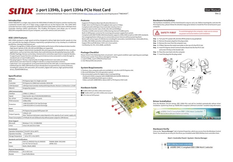
SUNIX SDC Series, industrial RS-232/422/485 and isolated Digital I/O PCI-Express add-on card, is
designed for PC-based IoT Gateway or desktop that enables data acquisition, I/O control and
serial communication in the industrial automation. This board built-in SUNIX UART & Digital-I/O
controller, QiuNiu, and as well built with many of SUNIX advanced features and technologies. In
addition, SUNIX provides API software and SDK library, allowing users to program under
Windows 10 operating systems. The software package includes a dynamic library.dll, as well as
C, C# programming language sample codes, making it easier to develop application software.
SUNIX PCI Express Industrial I/O Control Board enriches I/O expandable capacity with
cost-efficient design; SDC4880B is the best serial and digital I/O communicating solution and
SDC0880I is the best digital I/O communicating solution to enrich your system I/O expandable
capacity for lite industrial applications.
Introduction
Please check if the following items are present and in good condition upon opening package.
Contact your vendor if any item is damaged or missing.
- PCI Express Industrial I/O Control Board (SDC4880B or SDC0880I)
- DB44 to 2-port DB9 Male & 1-port DB25 Female connection cable, 100cm (SDC4880B only)
- DB25 Male to Female connection cable, 100cm (SDC0880I only)
- Serial RS-232 D-Sub 9-pin male with nuts on cable, 30cm, 2pcs (SDC4880B only)
- DB25 Male DIN-rail wiring board
Package Checklist
Specification
Board Level
Serial Ports (SDC4880B Only)
Parity bit
even, odd, none, mark, space
Interface
RS-232/422/485
Controller
16C950 UART Compatible
FIFO
128byte Hardware
Baud rate
50bps ~921.6Kbps
Terminator
120Ω
No. of port
4 ports
Data bit
5, 6, 7, 8
IRQ & IO
Assigned by System
Surge Protection
2KV Surge (Meets IEC61000-4-5 requirement)
Signal
RS-232: TxD, RxD, RTS, CTS, DTR, DSR, DCD, GND, RI
RS-422: TxD+, TxD-, RxD+, RxD-, GND
RS-485: Data+, Data-, GND
Flow Control
RS-232:CTS/RTS(H/W), DTR/DSR(HW), Xon/Xoff(S/W)
RS-422/485: Xon/Xoff(S/W)
PCB Connector
2 ports on DB44 Female connector;
2 ports on pitch 1.0 pin header connectors
Digital Input
Type
NPN & PNP
Channel
8-channel
Input Resistance
10KΩ
Isolation
2500 VDC
Frequency
2KHz max (Input)
Counter 32-bit (on all channel) Pin Define
DI1~DI8, COM, GND
Noise Reduction Digital Filter
PCB Connector DB44 Female connector for SDC4880B
Initial Protection
Auto-loading preset output value for booting & restart
PCB Connector DB25 Female connector for SDC0880I
PCB Connector DB44 Female connector for SDC4880B
PCB Connector DB25 Female connector for SDC0880I
Dry Contact
Logic Level 0: Open; Logic Level 1: Close to GND
Wet Contact
Logic Level 0: 0 to 3VDC; Logic Level 1: 10 to 50VDC
Interrupt Mode
Event trigger (Rising Edge, Falling Edge, Both modes)
& polling for all channels
Microsoft
Windows 10 (X86/X64)
SDK
Library:
DLL for Windows supporting C, C++, C# languages.
C, C# sample code available
Third Party
Software
Support
Support Node-RED serial and Modbus communication
module. (For SDC4880B only )
Capable of engaging with EdgeX device C SDK for EdgeX
service development.
Software Support
Digital Output
Type
NPN
Channel
8-channel
Voltage Range
3.5 to 40VDC
Isolation
2500 VDC
Current
500mA per Channel
Pin Define DO1~DO8, PWR, GND
Interface
Controller
BUS
IRQ & IO
ESD Protection
PCI Express
SUNIX QiuNiu UART & Digital-I/O controller
PCI Express Gen1 x 1 (single lane)
Assigned by System
±15KV IEC61000-4-2 Air Gap Discharge
±8KV IEC61000-4-2 Contact Discharge
Regulatory Approvals
Hardware CE / FCC / VCCI / BSMI
Environment
Operation Temperature -20 to 70°C (-4 to 158°F)
Operation Humidity 5 to 95% (non-condensing)
Storage Temperature -20 to 70°C (-4 to 158°F)
PCI Express
Industrial I/O Control Board
Quick Installation Guide Ver.1
Please visit SUNIX website https://www.sunix.com
For latest manual and driver update:
Pin Assignment
RS-232/422/485
Digital Input / Output
6
1 5
9
PIN
1
2
3
4
5
6
7
8
9
RS-232
DCD
RxD
TxD
DTR
GND
DSR
RTS
CTS
RI
RS-422
TxD-
TxD+
RxD+
RxD-
GND
RTS-
RTS+
CTS+
CTS-
RS-485
Data-
Data+
-
-
GND
-
-
-
-
PIN
1
2
3
4
5
6
7
8
9
10
11
12
13
Digital Input
DI COM
DI COM
DI GND
DI GND
DI 1
DI 2
DI 3
DI 4
DI 5
DI 6
DI 7
DI 8
NC
PIN
14
15
16
17
18
19
20
21
22
23
24
25
GND
Digital Output
DO PWR
DO PWR
DO GND
DO GND
DO 1
DO 2
DO 3
DO 4
DO 5
DO 6
DO 7
DO 8
NC
1 13
14 GND
The hardware installation of PCI Express Industrial I/O Control Board is easy to carry out. Before
inserting the card into the PCIe bus, please follow the detailed steps given below to install the
board in your computer.
Hardware Installation
Please plug the board in an available PCI Express slot first, before installing the driver.
Unzip the software file and Run setup.exe under Windows 10.
Driver Installation
Step 1: Turn your PC’s power off, and shut off the power to any peripheral.
Step 2: Remove the power plug from the plug socket.
Step 3: Remove the cover from the computer case.
Step 4: If fitted. Remove the metal cover plate on the rear of a free PCIe slot.
Step 5: Insert PCI Express Industrial I/O Control Board into the free PCIe slot
and screw it firmly on the bracket side.
Step 6: Place the cover back onto the computer.
Step 7: Insert the plug into the plug socket.
To avoid damaging to the computer, make sure to remove
any power connection before card installation.
SAFETY FIRST
Setup.exe
Hardware Verification
Please launch the �Device Manager� to verify hardware installation correctly.
Controller Panel > All Control Panel Items > Device Manager
◀ These COM number may be different
according to system assignment.
Device Manager


