sunjoe SJPH1500E User manual

© 2021 by Snow Joe®, LLC
All rights reserved. Original instructions. SAVE THESE INSTRUCTIONS
1
A Division of Snow Joe®, LLC Model SJPH1500E Form No. SJ-SJ-SJPH1500E-880E-M
R
OPERATOR’S MANUAL
ELECTRIC INFRARED HEATER
1500-WATT | FREE STANDING + WALL-MOUNTED
EN
IMPORTANT!
Safety Instructions
All Operators Must Read These
Instructions Before Use
Read all the instructions contained in this manual. Keep this
manual in a safe place, so that the information is available at
all times. If you give this equipment to another person, make
sure to provide these operating instructions. Basic safety
precautions should always be followed to reduce the risk of
explosion, which could cause property damage, personal
injury, or death.
Notice the safety alert symbol mused in this manual to draw
your attention to a WARNING given along with the particular
operating instruction. This means that the operation requires
special ATTENTION, CAUTION, and AWARENESS.
mWARNING! Surface temperatures become very
hot when operating the heater.
mWARNING!
1. Read all instructions before using this heater.
2. This heater is hot when in use. To avoid burns, do not let
bare skin touch hot surfaces. If provided, use handles
when moving this heater. Keep combustible materials,
such as furniture, pillows, bedding, papers, clothes, and
curtains at least 3 feet (0.9 m) from the front of the heater
and keep them away from the sides and rear.
3. Extreme caution is necessary when any heater is used by
or near children and whenever the heater is left operating
and unattended.
4. Always unplug heater when not in use.
5. Do not operate any heater with a damaged cord or plug
or after the heater malfunctions, has been dropped or
damaged in any manner. Discard heater, or return to
authorized service facility for examination and/or repair.
6. This heater is not intended for use in bathrooms, laundry
areas and similar indoor locations. Never locate heater
where it may fall into a bathtub or other water container.
7. Do not run cord under carpeting. Do not cover cord with
throw rugs, runners, or similar coverings. Do not route
cord under furniture or appliances. Arrange cord away
from trac area and where it will not be tripped over.
8. After shutting down the heater, remove plug from outlet.
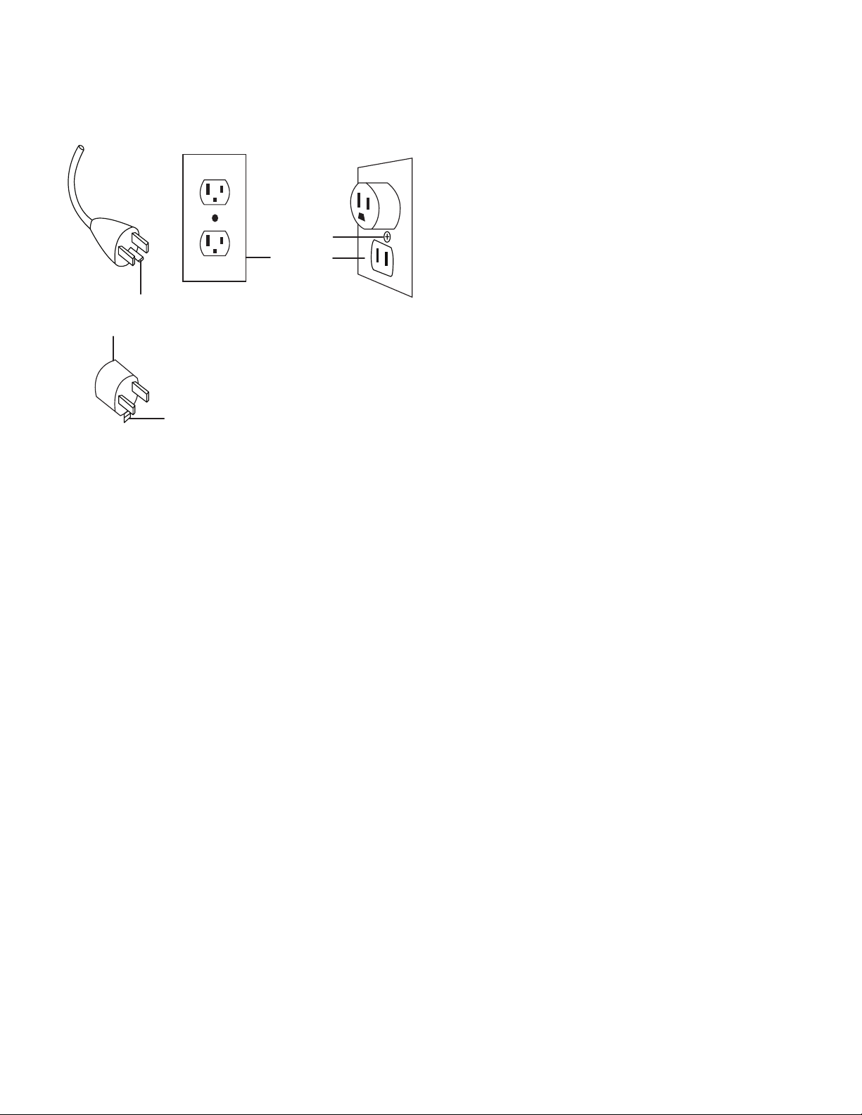
9. Connect to properly grounded outlets only.
10. Do not insert or allow foreign objects to enter any
ventilation or exhaust opening as this may cause an
electric shock or re, or damage the heater.
11. To prevent a possible re, do not block air intakes or
exhaust in any manner. Do not use on soft surfaces, like a
bed, where openings may become blocked.
12. A heater has hot and arcing or sparking parts inside. Do
not use it in areas where gasoline, paint, or ammable
liquids are used or stored.
13. Use this heater only as described in this manual. Any
other use not recommended by the manufacturer may
cause re, electric shock, or injury to persons.
14. Always plug heaters directly into a wall outlet/receptacle.
Never use with an extension cord or relocatable power tap
(outlet/power strip).
15. This heater is NOT to be operated by children.
16. The unit must be securely placed on a horizontal and at
surface, with the clearance of 3 ft to the wall and 1 ft to
the ceiling.
17. DO NOT cover the unit with anything during operation or
right after shutting down. Wait for 30 – 45 minutes for the
unit to cool down before storage.
18. DO NOT wrap the power cord on the unit.
19. When damaged, the unit must be repaired by an
authorized service center. If the power cord is damaged, it
must be replaced by the manufacturer, its service agent or
similarly qualied persons in order to avoid a hazard.
20. DO NOT use this heater with a programmer, timer or any
other device that switches the heater on automatically,
since a re risk exists if the heater is covered or positioned
incorrectly.
21. This appliance is NOT intended for use by persons
(including children) with reduced physical, sensory or
mental capabilities, or lack of experience and knowledge,
unless they have been given supervision or instruction
concerning use of the appliance by a person responsible
for their safety.
22. The unit is for household use only. It's NOT allowed to use
in building site, greenhouses, barn or stable where there's
ammable dust.
23. DO NOT use this unit as a cloth drier or towel drier.
24. DO NOT use this unit as a sauna heater.
25. DO NOT immerse this unit into water for cleaning.

2
Grounding Instructions
This heater is for use on 120 volts outlet only. The cord has a
plug as shown at A in the gure above. An adapter as shown
at C is available for connecting three-blade grounding-type
plugs to two-slot receptacles. The green grounding lug
extending from the adapter must be connected to a permanent
ground such as a properly grounded outlet box. The adapter
should not be used if a three-slot grounded receptacle is
available.
(A
)(
B)
(C)
Grounding pin
Metal screw
Cover of
grounded
outlet box
Adapter
Grounded means

3
Safety Symbols
The following table depicts and describes safety symbols that may appear on this product. Read, understand, and follow all
instructions on the machine before attempting to assemble and operate.
READ THE OPERATOR'S
MANUAL(S) – Read, understand,
and follow all instructions in the
user manual(s) before attempting
to assemble and operate.
SAFETY ALERT – Indicates a
precaution, a warning, or a danger.
WARNING! Do not expose the
unit to rain or wet conditions.
Keep dry.
WARNING! Electrical shock hazard.
Symbols SymbolsDescriptions Descriptions
HOT SURFACE – To reduce the risk of injury or damage, avoid contact
with any hot surface.

4
Know Your Infrared Heater
Read the owner’s manual and safety rules carefully before using your infrared heater. Compare the illustration below to the actual
unit in order to familiarize yourself with the location of the various parts and hardware. Save this manual for future reference.
1. Metal safety bar
2. Heater head
3. Control panel
4. Switch box
5. Power cord
6. Telescoping pole
7. Telescoping coupler
8. Upper pole
9. Remote control
10. Cord clips (2)
11. Middle pole
RR
22
Hardware Pack
15 16 17
18 19 20 21
12. Lower pole
13. Base
14. Plug
15. Hex key wrench
16. Base washer
17. Heater head knob
18. Wall anchors (4)
19. ST4x30 screws (4)
20. M6x12 screw
21. Wall-mounting bracket
22. Heater head cover
R
1
2
3
4
5
7
9
12
13
14
6
8
10
11

5
Technical Data
Power Input .................................... 120 V AC | 60 Hz
Maximum Wattage ......................... 1500 W
Heat Output .................................... 5118 BTUs
Heating Area ................................... 130 sq. ft. (12 m2)
Power Cord Length ........................ 6.6 ft. (2 m)
Adjustable Height ........................... 5.25 ft. – 6 ft.
(1.6 m – 1.8 m)
Adjustable Heating Head Angle ..... 0º – 25º
Net Weight ...................................... 26.4 lbs (12 kg)
Unpacking
Carton Contents
• Heater head
• Telescoping pole
• Upper pole with telescoping coupler
• Middle pole
• Lower pole
• Base cover
• Base
• Metal safety bar
• Hardware pack (hex key wrench, base washer, heater head
knob, 4 wall anchors, 4 ST4x30 screws, M6x12 screw, wall-
mounting bracket)
• Heater head cover
• Manual with registration card
1. Carefully remove the infrared heater and check to see that
all of the above items are supplied.
2. Inspect the product carefully to make sure no breakage or
damage occurred during shipping. If you nd damaged or
missing parts, DO NOT return the unit to the store. Please
call the Snow Joe®+ Sun Joe®customer service center at
1-866-SNOWJOE (1-866-766-9563).
NOTE: Do not discard the shipping carton and packaging
material until you are ready to use your new infrared
heater. The packaging is made of recyclable materials.
Properly dispose of these materials in accordance with
local regulations.
IMPORTANT! The equipment and packaging material are not
toys. Do not let children play with plastic bags, foils or small
parts. These items can be swallowed and pose a suocation
risk!
Assembly
Tools Required:
• Phillips screwdriver (not provided)
• Hex key wrench
• Drill (not provided)
Choose a spacious and level location for assembly. Remove all
parts from the packaging, and check for missing parts.
Floor Stand Set-up
1. Put lower pole through the base cover, base, and base
washer, tightly lock them with the provided hex key
wrench (Fig. 1).
2. Unscrew the 2 pre-assemble M6x12 screws from the
middle pole, connect the middle pole with the lower pole,
aligning the holes, and tighten with the 2 M6x12 screws
(Fig. 2).
3. Loose the pre-assembled telescoping coupler on the
upper pole, then insert the telescoping pole through the
bottom of upper pole (Fig. 3).
Fig. 1
Lower pole
Base cover
Base
Base washer
Hex key wrench
Fig. 2
Middle pole
Lower pole M6x12 screw

6
4. Secure the upper pole and the telescoping pole with the
coupler from the top of the telescoping pole (Fig. 4).
5. Unscrew 2 pre-assembled M6x12 screws from the upper
pole, then connect the upper pole assembly with the
middle pole, and tighten with the 2 M6x12 screws (Fig. 5).
6. Unscrew the 4 pre-assembled ST3x10 screws from the
back of the heater head, attach the metal safety bar on
the heater head and secure with the ST3x10 screws
(Fig. 6).
7. Connect the heater head with the telescoping pole with
the holes aligned and tighten with the M6x12 screw in the
hardware pack (Fig. 7).
Wall mount Set-up
NOTE: When mounting the heater head, make sure it's
mounted horizontally, or the tipping over protection will engage
and the unit will not start.
1. Make sure the desired mounting location can t the unit in
a horizontal orientation and is near an outlet but free from
electrical cables, communication lines, and pipes that
could be damaged by excessive heat.
2. Pre-drill the wall and insert the 4 wall anchors. Use the
bracket as a template for hole placement (Fig. 8).
Fig. 3 Telescoping
coupler
Upper pole
Telescoping
pole
Remove the
telescoping
coupler
Insert the telescoping
pole from the bottom of
the upper pole
Telescoping pole
Fig. 4
Telescoping
coupler
Upper pole
Fig. 5
Upper pole
Middle pole M6x12 screw
Fig. 6 Metal safety
bar
Heater head
ST3x10 screws
Fig. 7
Heater head
Telescoping pole M6 x 12 screw

7
Fig. 8
Wall anchors
Wall anchors
3. Use 4 ST4x30 screws to fasten the mounting bracket to
the wall with the wall anchors inside the pre-drilled holes
(Fig. 9).
4. Slide the heater head on the mounting bracket and make
sure the bracket is inserted fully in the heater head
(Fig. 10).
5. Fix the assembly by inserting the heating head knob from
the back of the heater head, screw the knob clockwise
until it cannot be turned further (Fig. 11).
Operation
NOTE: This infrared heater is designed for spot heating or as
a supplementary heat source. It's not intended to be the main
source of heat during cold months.
SwitchOn/O
1. Place the infrared heater on a level and non-combustible
surface. Plug in the appliance to an outlet, making sure
the power supply is same as rated. The indicator light on
the control panel will start ashing, which means it's in
standby status (Fig. 12).
2. Press the "I" button on the control panel to turn on the
heater. The indicator light will illuminate and the heater will
start working (Fig. 13).
Fig. 9
Wall
Wall-anchor in the
pre-drilled hole
ST4x30 screw
Mounting bracket
Fig. 10
Wall
Mounting bracket
Heater head
Fig. 11
Heater head knob
Fig. 12
Plug
Control
panel
Indicator
light

8
3. To switch o the heater, press the O button on the control
panel of the heater (Fig. 13).
Using the Remote Control
The heater can also be switched on and o with the equipped
remote control. The remote control is powered by two AAA
batteries (not included). Insert the batteries in the battery
compartment on the back of the remote control and use the O
button and I button on the front to control the heater (Fig. 14).
Adjusting the Heating Head
The position and angle of the heating head can be adjusted for
better heating result. Follow the instructions below to adjust
the heating head.
mWARNING! To avoid burns, do not touch the
heater head when the heater is working.
1. The height of the heater head can be adjusted when it's
connected with the oor stand. Before adjusting, make
sure the heater is turned o. Loosen the telescoping
coupler by twisting it counterclockwise. Pull out or push
in the telescoping pole to the desired length. Tighten the
telescoping coupler securely (Fig. 15).
NOTE: Make sure the telescoping coupler is locked
securely after adjusting.
2. To adjust the heater head's angle, grab the heater head
and adjust it to the desired position. The heater head can
be adjust between 0º and 25º (Fig. 16).
NOTE: Make sure the heater is shut o and completely
cooled down before adjusting the heater head's angle.
Overheating Protection
If the infrared heater is overheated, the equipped overheating
protection system will shut o the heater automatically to avoid
danger. Follow the instructions below if this happens during
use:
• Unplug the appliance and let it cool down for 30 - 45
minutes.
Fig. 13
O button
I button
R
Fig. 14
FRONT
Battery compartment
BACK
Fig. 15
Telescoping coupler
Telescoping pole
Fig. 16
0º
25º

9
• Remove objects around the appliance to ensure a well
ventilated area.
• When the heater is cooled down, plug in the heater again
and resume using.
Tipping-Over Protection
The infrared heater is also equipped with tipping over
protection, which will turn o the heater when it tilts around 40
degrees or more. Place the heater on a at, smooth, and stable
surface in order to prevent it from tipping over.
Maintenance
To enjoy years of outstanding performance from the infrared
heater, make sure you perform the following maintenance
activities on a regular basis.
mWARNING! DO NOT touch or move the appliance
for at least 30 – 45 minutes after use. Allow all heating
elements to cool before touching.
Cleaning
1. Turn o and unplug the appliance. Wait for the appliance
to cool down completely.
2. Clean the external surface by wiping it with a soft, damp
cloth. Do not use any abrasive detergent on the appliance
as it will cause damage.
Storage
1. Turn o and unplug the appliance. Wait for the appliance
to cool down completely. Store the appliance in a dry,
indoor space covered with the included cover.
2. Do not place any heavy items on top of the appliance as
this may cause damage to the appliance.
Support
If your Sun Joe®SJPH1500E infrared heater requires service or
maintenance, please call 1-866-SNOWJOE (1-866-766-9563)
for assistance.
Model and Serial Numbers
When contacting the company, reordering parts, or arranging
service from an authorized dealer, you will need to provide
the model and serial numbers, which can be found on the
decal located on the unit. Copy these numbers into the space
provided below.
Record the following numbers from your new product:
Model #:
Serial #:
S J P H 1 5 0 0 E
Table of contents
Other sunjoe Heater manuals