FUNCTION SETTING
1. OSD menu structure
SPECIFICATION
SK-P441(D)/M844AI
1/3" SONY SUPER HAD CCD
768(H) X 494(V) PIXEL(NTSC), 752(H) X 582(V) PIXEL(PAL)
6.35 (H) X 7.4 (V)(NTSC), 6.5 (H) X 6.25 (V)(PAL)
2:1 Interlace
Internal/ Line-Lock(option)
600 TV-LINE(COLOR), 700 TV-LINE(B/W)
52dB or More(AGC OFF)
1.0 Vp-p(Sync. Negative) Termination 75
γ= 0.45 typ.(0.45, 0.6, 1.0, user)
Yes(Multi Language)
ATW(2,500°K ~ 9,500°K)/MANUAL/AWC
1/60(1/50) ~ 1/100,000sec
Auto(Selectable limit 2X~256X)/FIXED/OFF
BLC, LWDR, DWDR, HLC(ON/OFF)
LOW/MIDDLE/HIGH/OFF
LOW/MIDDLE/HIGH/OFF
ON/OFF(240 Block)
ON/OFF(8 Zone)
H/V/BOTH/AUTO(option)
ON/OFF
ICR(AUTO, COLOR, B/W)
70pcs(LOW, MIDDLE, HIGH, OFF), Dynamic IR
ON/OFF
ON(10X)/OFF
AUTO/OFF
LOW/MIDDLE/HIGH/OFF
RS-485(Protocol : Pelco D, Pelco P)
Day & Night Vari-focal auto iris lens
12V DC ±10%(24V AC : option)
LED ON : Max. 1.1A, LED OFF : Max . 150mA
Yes
-20℃ ~ 50℃
-20℃ ~ 60℃
100(W) X 87.8(H) X 229(D)mm
Approx. 2kg
Ⅱ
㎛ ㎛ ㎛ ㎛
Ω
0.01Lux(F/1.2), 0.0003Lux(Sense up),
0Lux(70M Range at LED HIGH) - Indoor
Model No.
Image Sensor
Effective Pixel
Cell Size
Scanning System
Sync. Type
Resolution
S/N
Video Output
OSD
Sense up
AGC
DNR(3D)
Gamma
White Balance
Shutter Speed
Backlight
Motion Detection
Privacy Zone
Mirror
Freeze
Day & Night
LED Brightness
DIS
Digital Zoom
Blemish Compensation
Impact Detection
Communication(option)
Lens
Power Supply
Current Consumption
Fan
Operation Temp.
Preservation Temp.
Dimension
Weight
Min. Illumination
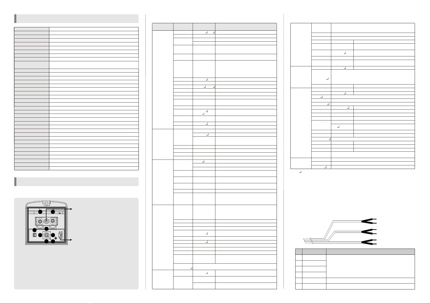
①SETUP :
②UP, ③DOWN :
④LEFT, ⑤RIGHT :
⑥EXT. VIDEO :
⑦Zoom, ⑧Focus :
Press "SETUP" button to go to the menu.
Use "UP" or "DOWN" button to go to the up or the
down.
Use "RIGHT" or "LEFT" button to go to the right or
the left.
Extra video output terminal for installation. The cable
is option.
Use a the 'TORX' screw driver for adjusting zoom
and focus.
Debug port : For factory and service
personnel only.
Zoom & Focus fixing screw :
Focal length adjustment direction
1. Unfasten the 'TORX' screw inside
2. Adjust two trimmers properly
3. Tighten the screw
When you tighten the screw,
don't put stress excessively.
<Caution>
FOCUSZOOM
EXT.VIDEO
2
45
3 1
6
8
U
D
LR
7
2. OSD menu structure
ㆍThe ' ' icon appeared with desired function, press the set button to move sub menu.
ㆍThe '- - -' icon appeared with function that is unavailable according to function setting.
3. How to control through RS-485 communication(option)
4. Cable array(option)
1) Match the camera with controller's ID, baudrate and protocol
2) Up, Down, Left and right of Jog lever is same as Up, Down, Left and
right of RS-485 controller
3) Enter of Jog lever is the same as menukey or IRIS open key of RS-485
controller
E : ORANGE(RX +)
F : WHITE(RX -)
A : BLUE(MOTION)
B : BLACK(GND)
C : GREEN(IMPACT)
D : BLACK(GND)
0~99
AUTO
OFF, LOW,
MIDDLE, HIGH
OFF,
X2~X256
OFF, ON
OFF, ON
0~20
0~60
0~70
0~100
3~12
OFF, ON
AUTO
0~60
OFF, ON
0~20
ATW
MANUAL
AWC↓
0~255
0~255
0~255
0~255
AUTO
COLOR
B&W
65~160
30~125
3~12
OFF, ON
OFF,
MODE1,
MODE2
OFF,
VERT,
HORI,
BOTH,
AUTO(option)
0~49
OFF, ON
OFF, ON
0~50
OFF, ON
X1.0~X10
-128~127
-110~109
OFF, ON
OFF, ON
NONE
MESSAGE
Fixed focal lens or Vari-focal auto iris lens
Adjust the brightness
Shutter speed auto adjustable
Select shutter speed manually
Determines that use the AGC function or not
and AGC level selectable(You can not use the
Auto D&N change mode when AGC is off)
Using sense up when it is low luminance
(OFF, x2~x256 selectable)
When the Sense-up is activated and the camera
detects motion, operates LED and changes to
B/W mode if this mode is activated. Then user
can see vivid images without the afterimage.
(You can set this mode when the camera has
LED and the D&N mode is setto "Color".)
BLC function
Adjust BLC level
Select LWDR
Adjust WDR level
Using the Auto mode, set the WDR ON brightness
Using the Auto mode, set the WDR OFF brightness
Using the Auto mode, set the WDR switching
delay time
Digital Wide Dynamic Range
High Light Compensation(Using the Auto mode,
the HLC is not activated in day light.)
According to the threshold value, the camera
will recognize as High light or not.
Reduce noise in low illumination
Level is selectable
Color temperature 2500 ~ 9500°K
Adjust the Red or Blue values
Move the camera lens toward to white paper
then press the set button to find the optimal
white balance for current environment
Adjust the Red value to shift the colorof the object
Adjust the Blue value to shift the color of the object
Adjust Red tone of the image
Adjust Blue tone of the image
Auto day&night switching mode
Fixed at color(LED OFF)
Fixed at B/W(LED level selectable)
Select brightness of illumination about changing
the day ↔ night mode
Select the duration time about changing the
day ↔ night mode
Determines whether to transmit the burst signal
or not in B/W mode
IR LED OFF/ON and output level adjustable
When IR LED is turned on in B/W, the objects
can be clearly identified due to the function
that decreases screen saturation of objects
within a short distance.
VERT : Set a vertical image inversion
HORI : Set a horizontal image inversion
BOTH : set a image rotation
AUTO : Automatically rotate the screen according
to the camera's position
Sharpness adjustable
Gamma adjustable
Get a still image
Determines whether to use the brightness
compensation of four lens' corners(LSC) or not
The LSC level selectable
Max 10x digital zoom available(Default value is X3)
Digital zoom adjustable
Zoomed in image can be moved to horizontal
Zoomed in image can be moved to vertical
This function can be mitigates image movement
from external factors(This function uses digital
zoom)
Determines whether to use the motion detection
function or not
No display on the screen though movement is
detected
The words 'MOTION' appear on the screen when
movement is detected
LENS
LEVEL
E.SHUTTER
AGC
SENSE UP
ANTI-
GHOST
BLC
LEVEL
LWDR
LEVEL
OFF→ON
ON→OFF
DELAY TIME
DWDR
HLC
LEVEL
DNR
LEVEL
WB MODE
R-Y GAIN
B-Y GAIN
D&N MODE
DELAY TIME
BURST
LED LEVEL
DYNAMIC IR
FLIP
SHARPNESS
GAMMA
FREEZE
LSC
LEVEL
DZOOM
ZOOM
PAN
TILT
DIS
MOTION
DISPLAY
Function
setting menu Select menu ContentsSub menu
MANUAL , DC
1/60(1/50)~1/100,000
MANUAL BLUE
MANUAL RED
BW COLOR→
COLOR BW→
0.45, 0.6, 1, USER
1. EXPOSURE
3. DAY&NIGHT
4. IMAGE ADJ.
2. WHITE
BALANCE
5. ALARM
PATTERN
GENERATOR
Motion detection sensitivity
Set the duration of alarm out. If the way of display
is message, it means display time of message
Determines whether to use impact detection
function or not
Sensitivity setting
Set the duration of alarm out and display time
of "IMPACT" message
Display each privacy mask or not.
Select mask color(8 color is available)
Select language
Display the camera ID on the screen
Defect pixel correction in low illumination
Setup the limited value of white pixel correction
Setup the limited value of black pixel correction
Setup the DPC(Defect Pixel Correction) level
Internal Sync with 12V DC power
Setting the phase is selectable when used
24V AC(Dual power only)
Phase contollable at 24V AC input(L/L mode)
Monitor setting
Select the camera ID for RS-485 communication
Select baud rate
Select protocol
0~120
1~15
OFF, ON
1~15
OFF, ON
BLACK, GRAY…
ENGLISH, …
OFF, ON
OFF, AUTO
0~255
0~255
0~255
INT
L/L
0~255
CRT, LCD
1~255
SET
WINDOW
ALL SET↓
SENSITIVITY
HOLD TIME
IMPACT
SENSITIVITY
HOLD TIME
MASK 1 ~8
SET
WINDOW
COLOR SET
LANGUAGE
TITLE
EDIT
RESET↓
POSITION
DPC
WHITE THR
BLACK THR
DPC LEVEL
SYNC
VPHASE
MONITOR
COM. ID
BAUDRATE
PROTOCOL
FACTORY
SET↓
EXIT↓
RETURN
7. SPECIAL
6.PRIVACY
ZONE
8. EXIT
2400, 4800, 9600
PELCO-D, PELCO-P
COMMUNICATION
SAVE AND EXIT↓
OFF, LOW, MIDDLE, HIGH
OFF, ON , AUTO
OFF, LOW, MIDDLE, HIGH
Test signal. Press the set button, color bar appeared on the screen
and press any key to return to menu
LOW, MIDDLE, HIGH
5. ALARM
ALL CLEAR↓
Press the set button to move into the motion detection area section
to set the 240 blocks. To escape this menu, you should press the
left button at the far left or press the right button at the far right
Press the set button to select all area
Press the set button to remove all area
Camera ID setting
Camera ID reset
Camera ID position
Press the set button at first time, you can move the mask's
position. After press the set button again, you can adjust the size
of mask. If you press the set button once more, you can adjust
position of edge. After decided position of edge then press the
set button, it will be back to previous menu.
Communication setting
Reset your camera to factory default condition and then restart
Notice : Lens, communication and language is not changed
Save the value and then restart
Escape the menu without save
Move back to previous menu
※All specification is subject to change without notice to improve the quality.
MOTION ALARM
GND
IMPACT ALARM
GND
RX +
RX -
A
B
C
D
E
F
FUNCTION
ㆍ If the camera detected motion when using Motion & Impact
function, outside line of motion alarm connect with GND(B).
ㆍIf the camera detect impact, outside line of impact alarm connect
with GND(D). Outputs of Motion & Impact are 'open collector'.
ㆍMax current & voltage are 200mA and 30V DC.
RS-485A
RS-485B
REMARK
No.
3B15451B


