Sunstar Machinery KM-250BL Series User manual

SSUUNNSSTTAARR MMAACCHHIINNEERRYY CCOO..,, LLTTDD..
User’s
Manual
KM-250BL Series
High speed, one needle,
sewing machine with
automatic thread trimmer
1) For proper use of the machine, thoroughly
read this manual before use.
2) Keep this manual in a safe place for future
reference in case the machine breaks
down.
MMMMEE--005500550099

Best Quality
Best Price
Best Service
SSUUNNSSTTAARR MMAACCHHIINNEERRYY CCOO..,, LLTTDD..
R
1.
Thank you for purchasing our product. Based on the rich expertise and
experience accumulated in industrial sewing machine production, SUNSTAR
will manufacture industrial sewing machines, which deliver more diverse
functions, high performance, powerful operation, enhanced durability, and
more sophisticated design to meet a number of user’s needs.
2. Please read this user’s manual thoroughly before using the machine. Make
sure to properly use the machine to enjoy its full performance.
3. The specifications of the machine are subject to change, aimed to enhance
product performance, without prior notice.
4.
This product is designed, manufactured, and sold as an industrial sewing
machine. It should not be used for other than industrial purpose.

Safety rules for machine ...................................................................................................... 4
1. Specification..................................................................................................................... 8
1) Automatic thread trimming sewing machine............................................................................................................ 8
2) Servo motor................................................................................................................................................................ 8
3) 470 motor ................................................................................................................................................................... 8
4) 470 motor control....................................................................................................................................................... 9
5) Peripheral automation device (optional) ................................................................................................................... 9
2. Installation ...................................................................................................................... 10
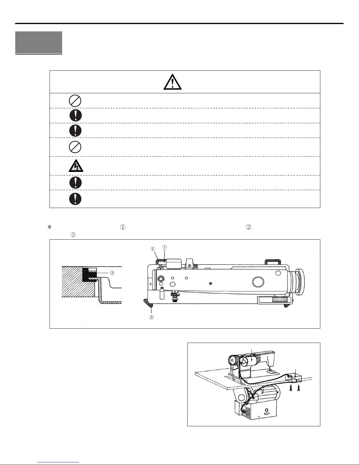
1) Installation of machine head..................................................................................................................................... 10
2) Installation of automatic knee lifting solenoid and power switch box.................................................................... 10
3) Lubrication ................................................................................................................................................................ 11
4) Adjustment of belt tension........................................................................................................................................ 12
5) Installation of the program unit ................................................................................................................................ 12
6) Installation of the belt cover ..................................................................................................................................... 13
7) Location detector assembling and its control method. ............................................................................................ 13
8) Adjustment of location detector ............................................................................................................................... 14
9) Check for the stop position of the machine.............................................................................................................. 15
10) Reverse button function.......................................................................................................................................... 15
3. Adjustment of the Machine............................................................................................ 16
1) Inserting the needle .................................................................................................................................................. 16
2) Adjusting needle bar ................................................................................................................................................ 16
3) Adjusting timing of needle and hook ...................................................................................................................... 16
4) Adjusting oil flow in thread take up........................................................................................................................ 17
5) Adjusting oil flow of the hook ................................................................................................................................ 17
6) Inserting lower thread and adjusting thread tension ................................................................................................ 18
7) Routing the upper thread .......................................................................................................................................... 19
8) Adjusting the upper thread........................................................................................................................................ 19
9) Adjusting the height and pressure of the presser foot.............................................................................................. 20
10) Adjusting automatic knee lifter (optional) ............................................................................................................. 21
11) Adjusting stitch length ............................................................................................................................................ 21
12) Adjusting the height and slope of feed dog............................................................................................................ 21
13) Adjusting the trimming device ............................................................................................................................... 22
14) Adjusting knife tension........................................................................................................................................... 25
15) Exchanging movable knife .................................................................................................................................... 26
16) Exchanging fixed knife........................................................................................................................................... 26
17) Adjusting wiper....................................................................................................................................................... 27
18) Adjusting feed cam ................................................................................................................................................. 27
4. Causes of trouble and troubleshooting......................................................................... 28
1) Sewing machine troubleshooting ............................................................................................................................. 28
Table of contents

Safety Rules for Machine
Safety labels in the manual are categorized into danger, warning and caution.
Failure to follow the safety rules may result in physical injuries or mechanical damages.
The safety labels and symbols are defined as follows.
[The meaning of the safety labels]
Instructions here shall be observed strictly. Otherwise, the user will be killed or suffer
severe physical injuries.
Instructions here must be observed, or the user could suffer fatal or severe physical
injuries.
Instructions here should be observed, or the user could face physical injuries or
mechanical damages.
Danger
[The meaning of symbols]
This symbol means a must-not.
Warning
Caution
4
This symbol means that an electric shock may be caused if the
instruction is not followed properly.
This symbol means a must for safety.

1-1) Machine
mobilization
Danger
1-2) Machine
Installation
Caution
1-3) Troubleshooting
Danger
In need of troubleshooting, it should be done by the trained A/S engineer of our
company.
ⓐ
Ahead of cleaning and repair, be sure to shut off the power supply. And wait for about 4
minutes till the machine discharges completely.
ⓑ
Even a part or all of the machine should not be modified without any consultation with our
company.
ⓒ
In case of repair, you should change the damaged part into the standard article of our company.
ⓓ
After repair, please put again the safety cover disjointed while repairing.
Only personnel with a full understanding of the safety rules should move the
machines. The following directions must be observed when delivering the machines.
ⓐ
At least two persons should work together.
ⓑ
In case the machine should be transported, please wipe the oil covered on the machine to
prevent accidents.
Because physical damage such as the functional obstacles and breakdowns are
likely to occur according to the environment in which the machine is being installed.
Therefore, the following preconditions should be fulfilled.
ⓐ
Please keep the order from top to bottom when unpacking the package. Especially, mind
that the nail on the boxes.
ⓑ
Because machines are apt to be contaminated and corroded by dust and moisture, you
should install the climate controller and should clean the machines regularly.
ⓒ
Keep the machines out of the direct rays of the sun.
ⓓ
Keep both sides and the backside of the machines off at least 50cm from the wall to secure
enough space to repair.
ⓔ
Don’t run the machine near the places with the dangers of explosion. Don’t run the
machine near the places with the dangers of explosion, including the places where the
spraying product like aerosol are used in large quantities or oxygen are dealt with, unless
the exact actions concerning the operation are guaranteed to avoid the explosion.
ⓕ
Because of the peculiarity of the machine, any illuminators are not equipped. So, users
should install the lighting apparatus around the working area.
[Note] The details about the installment of the machine are described in No. 2
Installation.
5

6
KM-250BL series are manufactured for industry use to sew textiles and other similar
material. In case of running the machine, users should observe the following things.
ⓐ
Ahead of operating the machine, please read the manual and understand fully the details on its
operation.
ⓑ
Don’t forget to put on the garment suited for the safe work.
ⓒ
Keep your hands or a part of the body away from the running part of the machine like a needle,
hook, thread take-up spring and pulley etc.
ⓓ
Don’t remove. any kind of cover for safety while running the machine.
ⓔ
Be sure to connect the earthed line.
ⓕ
Before opening the electric box such as a control box, be sure to shut off the power supply and
make sure that the power switch should be put on “off.”
ⓖ
When threading the needle or before checking after sewing, be sure to stop the machine.
ⓗ
Don’t switch on the power supply with the foot on the pedal.
ⓘ
Don’t run the machine when the cooling fan are not running. Be sure to clean the air filter in
the control box once a week.
ⓙ
If possible, keep off from the strong electronic wave like a high frequency welding machine.
1-4) Machine
Operation
Warning
Warning
ⓐ
Safety Label: Suggestions while running the machine are stated.
ⓑ
Thread take-up spring cover: the device to prevent the human body from touching the thread
take-up spring.
ⓒ
Belt cover: the device to prevent hands, feet and clothing from getting jammed by the belt.
ⓓ
Finger guard: the device to prevent fingers from contacting the needle.
1-5) Safety Device
Warning
Always start the machine with safety covers in place since
fingers or hands could be injured or cut off by the belt. Turn off
the power switch during check-ups or adjustments.
ⓓ
ⓐ
ⓒ
ⓑ

7
“Caution mark” is attached to the machine for safety. In case of starting to run the
machine, read the directions of “Caution mark” carefully.
1-6) Position of
Caution Mark
1-7) Content of
“Caution”
Caution
CAUTION
경고
Do not operate without finger guard and
safety devices. Before threading, changing
bobbin and needle, cleaning etc. switch off
main switch.
손가락 보호대와 안전장치 없이 작동하지
마십시오.
실, 보빈, 바늘교환시나 청소전에는 반드시
주전원의 스위치를 꺼 주십시오.
CAUTION
경고
Hazardous voltage will cause injury.
Be sure to wait at least 360 seconds before
opening this cover after turn off main switch
and unplug a power cord.
고압 전류에 의해 감전될 수 있으므로 커버를
열 때는 전원을 내리고 전원 플러그를 뽑고
나서 360초간 기다린 후 여십시오.
CAUTION
경고
Do not operate without finger guard
and safety devices. Before threading,
changing bobbin and needle, cleaning
etc. switch off main switch.
손가락 보호대와 안전장치 없이 작동하지
마십시오.
실, 보빈, 바늘교환시나 청소전에는 반드시
주전원의 스위치를 꺼 주십시오.
CAUTION
경고
Hazardous voltage will cause injury.
Be sure to wait at least 360 seconds
before opening this cover after turn
off main switch and unplug a power
cord.
고압 전류에 의해 감전될 수 있으므로 커버를
열 때는 전원을 내리고 전원 플러그를 뽑고
나서 360초간 기다린 후 여십시오.
[Position of Caution Mark]

1) Automatic thread trimming sewing machine
KM-250BL
8
1
Specification
Item
KM-250BL
KM-250BL-7S
KM-250BL-7N
Usage
Heavy Material
Heavy Material
Heavy Material
Max speed
Max 3500spm
(Average 3000spm)
Max 3500spm
(Average 3000spm)
Max 3500spm
(Average 3000spm)
Max stitch Length
0~7mm
0~7mm
0~7mm
Needle
DB 1×#20~#23
DB 1×#20~#23
DB 1×#20~#23
Presser Foot Height
Manual 5.5mm
Knee 14mm
Manual 5.5mm
Knee 14mm
Manual 5.5mm
Knee 14mm
2) Servo motor
MODEL
SC55-1A
SC55-2A
SC55-3A
VOLT
ONE PFAHSE 110V
ONE PFAHSE 220V
THREE PHASE 220V
WATT
550W
550W
550W
HERTZ
50/60 Hz
50/60 Hz
50/60 Hz
3) 470 motor
MODEL
PM470
PHASE
1 : 1
1 : 1
3 : 3
3 : 3
1 : 1
3 : 3
HERZ
5 : 50Hz
6 : 60Hz
5 : 50Hz
6 : 60Hz
5 : 50Hz
6 : 60Hz
5 : 50Hz
6 : 60Hz
5 : 50Hz
6 : 60Hz
VOLT
1 : 110V
2 : 220V
3 : 380V
4 : 110V / 220V
5 : 220V / 380V

9
4) 470 motor control
MODEL
PC470
VOLT
1 : 110V
2 : 220V
MODEL
A
SUB CLASS
001
UsageModelOptional device
5) Peripheral automation device (optional)
AUTO KNEE LIFTING
SYSTEM
PRODUCTION COUNTER
MATERIAL EDGE SENSOR
STANDING PEDAL
SCOUN-1
SEDG-1
SEDG-2
SPDL-1
SPDL-2
A counting device which indicates the completed quantity on the
program unit panel, including added, subtracted, corrected or
remaining quantity along with other performance rates.
A device that senses the edge or thickness of the sewing material
to stop the machine without manual pedaling. Available in two
types: SEDG-1 for edge sensing type and SEDG-2 for thickness
sensing type.
An essential device when one person is operating multiple sewing
machines. Has different pedals for acceleration, thread trimming,
presser foot and ascending pedal. Types consist of SPDL-1 EDPL-
1 for fixed speed and SPDL-2 EDPL-2 for variable speed.
SPF-5
A solenoid operating structure where the presser foot gets lifted
automatically with pedal reverse gear stage 1 operation.
·
max. stroke: 10.3mm
·
input voltage: DC 24V (DC 24 ~ 46V)
·
induction at 10.3mm stroke: 26kg

10
1) Installation of machine head
Insert two machine head hinges into the bed holes. After aligning it with the rubber hinge , stand the machine on the rubber
cushion that is in the direction of the user.
[Figure 1]
2
Installation
Caution
▶Installation of the machine should be performed by a trained engineer.
▶Any electrical wiring must be performed by a qualified technician or agent.
▶The machine weighs over 32kg. At least 2 persons should carry out the installing work.
▶Plug in after the installation is complete. If the operator mistakenly steps down on the pedal
with the plug in, the machine will start automatically and can cause physical injuries.
▶Connect the ground (earth) wire. An unstable connection may result in an electric shock or a
malfunction.
▶Place the belt cover on top of the machine.
▶Use both hands when bending the machine backwards or returning it to the normal position.
Using only one hand can lead to severe hand injuries the weight of the machine.
2) Installation of automatic knee lifting
solenoid and power switch box
(KM-250BL-7N)
A. Installation
a) Attach the power switch box to the area of motor under
the table.
b) As can be seen in Figure2, attach connecter from the
solenoid to controller box through the power switch box.
(See, connecter part of controller box in page11-B)
[Figure 2]
Automatic knee lifting solenoid
Power switch box
Controller box

11
3) Lubrication
A. Attach the magnetic chip remover
Attach the magnetic chip remover in the accessory box to
the oil pump in the bed. (See Figure 3)
Do not use the magnet for other purposes. If the machine
runs without the magnet, it will cause trouble or do
damage durability.
[Figure 3]
Magnet
Oil pump
B. Lubricating the oil fan
a) Fill the lubricant up to the “HIGH” mark. (See Figure 4)
b) The lubricant must be SUNSTAR’s oil provided
exclusively for industrial sewing machines or SHELL’s
Tellus C10.
c) If the oil in use is down to the “LOW” mark, fill in to
“HIGH” immediately.
d) Once every two weeks is deemed the appropriate interval
for oil refills.
[Figure 4]
HIGH
OIL
LOW
Caution
▶Plug in only after oil supply is finished. If the operator mistakenly steps on the pedal with the
plug in, the machine will start automatically and can cause severe injuries.
▶When handling lubricants, wear protective glasses or gloves to avoid contact with your eyes or
skin. Inflammation may be caused otherwise. Never drink lubricants since they can cause
vomiting or diarrhea. Keep out of the reach of children.
▶Operate the machine only after adding oil when the machine is being used for the first time or
has been left unused for a long time.

12
4) Adjustment of belt tension
After installing the motor, unfasten the fixing units , up
and down and tension will be created to the belt due to
motor failing by gravity. And fasten the fixing nut and
then the fixing nut tightly. (See, Figure 5)
[Figure 5]
5) Installation of the program unit
A. Installation of Installation of automatic knee lifting
solenoid
a) Fix the bracket , on to the program unit , using 4
fixing nuts .
b) Use 2 fixing bolts and 3 fixing nuts to fix the bracket
tightly.
[Figure 6]
B. Installation of manual knee lifter
a) Fix the bracket on to the program unit , using 4
fixing nuts .
b) Then, use 3 fixing bolts to tightly
fix. (See, Figure 7)
[Figure 7]

13
6) Installation of the belt cover
A. Attach belt cover A onto the machine body using fixing
nut and washer .
If the machine is laid down on its back, it will be easy to
assemble. (See, Figure 8)
[Figure 8]
B. Attach belt cover B onto the table
Make sure that the belt properly operates without
interference from the belt cover “B”.
[Figure 9]
7) Location detector assembling and its
control method
A. Installation of location detector
a) Installing on the servo motor (in-built location detector)
A sensor of location detector is attached to the back side
of the arm. The appropriate clearance between the
location detector and the pulley is 0.5mm.
(See, Figure 10)
[Figure 10]
0.5mm

14
B. Installation of 470 MOTOR
Assemble parts in the order of marked number as can be seen in figure11. Then following the figure 12, make adjustments to
place the photo film at the center of the photo interrupter, by moving the shaft to the right and left. Then, tighten the 2 fixing nuts
using the hexagonal wrench.
[Note]
a) As can be seen on figure 12, make sure that the marks “DOWN” and “UP” face 4 the front when looking from the pulley side.
b) Film adjustment is completed upon shipment.
[Figure 11] [Figure 12]
Speed sensor flim
Location
detector
shaft
Fixing
washer
Clearance adjusting bushing
Fixing washer Fixing bushing
Fixing nuts
Pulley L wrench
Fixing nuts (2) of synchro shaft
Synchro shaft
Photo flim
Photo interrupt
COVER
PCB holder
8) Adjustment of location detector
A. For in-built location detector
Adjust the up-stop position of the needle such that the white carved sign on the pulley is in a straight line with the carved sign
on the arm when the needle has stopped in the air. That adjustment can be made by loosening the pulley’s clamp screw on
the side with N U carved signs and moving it sideways. Adjust the down-stop position of the needle such that the needle is on
the point of moving up when the needle bar is at the lowest point. This adjustment can be made by loosening the pulley’s clamp
screw on the side with N D carved signs and moving it sideways. (See, Figure 13&14)
[Figure 13] [Figure 14]
Up-stop
Down-stop

15
B. For 470 motor (external location detectors)
Turn the pulley manually to position the needle bar at the lowest point about to move back up. Then, loosen the fixed screws on
the film as in Fig. 11 and align the “DOWN” film with the film adjustment baseline and the sensor housing baseline as in Fig.
15&16. Tighten the fixed screws just enough so that the film does not rotate. In the same way, place the thread take-up lever at
the highest point, then loosen the fixed screws again and adjust the “UP” film as in shown the figure. Be careful that the
“DOWN” film A that was tightened before does not move when adjusting the “UP” film.
Figure 16 enlarges the film position. As can be seen in figure 16, set the end of film-adjusting arrow to sensor base.
[Figure 15] [Figure 16]
Setting the film when
the needle is in a up-
stop position
Setting the film when the
thread take-up lever is at
the highest point
Film-Adjusting Arrow
Setting Area
Sensor
Baseline Film Adjusting
Base
Sensor Base
9)
Check for the stop position of the machine
Check for the machine stop position after moving the needle up
and down by pushing the reverse button. See whether the
carved sign on the arm and the white carved sign on the pulley
are aligned when the needle is in an up position. If not,
adjustment to the photo film of the location detector or to the
location of the magnetic holder will be necessary since there
may be problems with the trimming. In other words, the
needle’s up-stop position should be identical with the stop
position of the needle bar after the trimming operation, which
would signify that there is nothing wrong with the operation
timing of the trimmer. (See Figure 17) (Refer to the explanation
about the Adjustment of Location Detector on page 13.)
[Figure 17]
White carved sign
10)
Explanation of reverse button function
Pressing the back tack button or reverse button during forward
sewing will start reverse sewing immediately. When you stop
the machine and restart it by stepping down on the pedal with
the reverse button already pressed down, you can perform
reverse sewing from the beginning. When the machine is in a
“stop” mode, you can change the up-down position of the
needle bar by pressing the reverse button. Lightly pressing the
button once when the needle is in a down-stop position will stop
the needle bar in a high position. Pressing the reverse button
twice within less than a second when it is in an up-stop position
will stop the needle bar in a low position. In short, the button
delivers two functions: one for reverse sewing and the other for
converting vertical position of the needle. (See Figure 18)
[Figure 18]
Down-stopUp-stop
Arm carved sign
Reverse button

16
3
Adjustment of the Machine
Caution
▶Always turn off the power when mounting a needle.
If the operator mistakenly steps on the pedal while the power is on, the machine will start
automatically and can result in physical injuries.
▶When using clutch motor, be aware that the motor will continue to rotate for a while even after
the power is switched off due to inertia.
Start to work on the sewing machine only after the motor has come to a complete stop.
1) Inserting the needle
Place the upper end of the needle closely adhered to the upper
side of the stopper hole , with the needle groove facing
inward. Fix the needle with a fixing screw . (See Figure 19)
[Figure 19]
[Figure 20]
HOOK
0.05~0.1mm
0.5mm
2) Adjusting needle bar
As can be seen in figure 20, pull out the rubber cover of needle
bar adjusting hole and turn the pulley to place the bar at the
lowest part. Then, loosen the needle bar clamp screw and
make the carved sign of the lowest bar meet the lower part
of needle bar down- bushing by moving the bar. When is
done, fix the clamp screw and clog the rubber cover .
3) Adjusting timing of needle and hook
As can be seen in figure 20, make the lower side of needle bar
bushing meet the carved sign of hook marked in the
needle bar and then loosen three hook fixing screws .
Turn the loose hook so that the hook edge meets the needle
center. When this is done, adjust the distance between the hook
edge and the inner side of the needle groove to 0.05~0.1mm.
Then, tighten three fixing screws again.

17
4) Adjusting oil flow in the thread take- up
As in the figure 21, the more the point of the control plate of
oil flow goes close to the center of hole of thread take-up
crank shaft, the more oil comes. On the other hand, the more
the point goes close to the corner of the link cam washer, the
less oil comes.
And when the point goes past the corner of the link cam
washer, the oil does not come out.
[Figure 21]
5) Adjusting oil flow of the hook
A. Check oil flow
a) After 3-minute idle operation of the machine, put the
paper at the place as in figure 22. And rotate the machine
for a 5 second. The amount of oil can be checked by the
oil sprayed on the paper.
b) Implement the test three times to find out whether it is
short or abundant. The appropriate flow is one that does
not exceed or lack based on the flow in the picture.
( If oil flow is not enough, the hook will not operate
properly. If oil flow is too much, the cloth may be
contaminated by oil.)
B. Adjusting oil flow
Turning the oil adjusting screw clockwise increases the
oil flow, and counter clockwise decreases the oil flow.
[Figure 22]
Hook
Bed
Oil fanOil flow test paper
Sprayed oil
Minimum standard
0.5mm
3~10mm
1mm
Maximum standard
Less More
Sprayed oil

18
Caution
▶Turn off the power when adjusting the lower thread tension.
If the operator mistakenly steps on the pedal, the machine will start automatically and can
cause physical injuries.
▶When using the clutch motor, be aware that the motor will continue to rotate for a while after the
power is switched off due to inertia.
Start to work only after the motor has come to a complete stop.
6) Inserting lower thread and adjusting thread tension
A. Put the bobbin into the bobbin case . And insert the thread into the thread groove and then wind it from the back to the
front of the tension adjusting plate spring . Turning the tension adjustment nut of the hook clockwise makes the lower
thread tension stronger and counterclockwise makes it weaker. When hold the end of thread, make sure that the bobbin case
should drop by gravity in order to adjust the lower thread tension. ( See Figure 23)
B. Removing bobbin case
With hand of the bobbin case , insert the bobbin case in to hook. Pull the hand to remove the case. (the bobbin is removed
when the hand is off) ( See Figure 23)
[Figure 23]
Weak
Strong

19
Caution
▶Turn off the power switch when routing the upper thread.
If the operator mistakenly steps on the pedal while switched on, the machine will start
automatically and can cause physical injuries.
▶When using the clutch motor, be aware that the motor will continue to rotate for a while after the
power is switched off due to inertia.
Start to work on the sewing machine only after the motor has come to a complete stop.
7) Routing the upper thread
Place the thread take-up lever to the highest position and insert the upper thread in the order of marked number as can be seen in figure24.
[Figure 24]
8) Adjusting the upper thread
A. Thread adjustment
As can be seen in figure 25, turning the tension adjustment
nut of the thread adjusting device clockwise makes the
lower thread tension stronger and counterclockwise makes it
weaker. Adjust the thread tension responding to the situation
because adjustment of the thread tension changes according
to sewing conditions such as the sewing material, used
thread and stitch length.
B. Adjusting the tension of the thread take up spring
As can be seen in figure 25, insert the driver into the groove
of the thread adjusting device . Turn clockwise to make
the spring tension stronger and counter clockwise to make it
weaker.
C. Auxiliary thread adjustment
As can be seen in figure 26, turning the thread tension
adjustment nut clockwise makes the thread length after
trimming shorter and counterclockwise makes it longer. The
adequate length of upper thread after trimming is 30~40mm.
[Figure 25]
Good sewing
[Figure 26]
Weak
Strong
Upper thread tension is strong
Upper thread tension is weak

20
D. Adjusting the thread release stroke
a) When the trimming solenoid is in action, adjust to make the opening of the thread tension adjusting plate 1mm.
b) For the adjustment, loose cable fixing nut of the thread release and wire. (See figure 27)
[Note]
If the plates are closely plates are closely adhered to each other, the upper thread length will be short and then the
thread will release next. In addition, if the plates are widely adhered to each other, the plates will be open and be a cause
for bad tension capability.
[Figure 27]
Wire
0.5~1mm-wide open
Cable fixing nut of the
thread release
Caution
▶After disassembling and adjusting a safety device, always place it back to the original position
and check whether it functions as intended.
▶Use both hands when pushing the machine backward or returning it to the original position. Due
to the weight of the machine, your hand can get stuck in the machine if you should slip.
▶When adjusting the machine with the switch on, be sure to pay extreme caution.
▶Only trained engineers must perform troubleshooting or inspection of the machine.
▶For electrical repair or inspection, consult with qualified technicians or agent.
9) Adjusting the height and pressure of
the presser foot
A. As can be seen in figure 28, lift the rubber cover , drop the
presser foot on the needle plate, and loosen the presser
fastening screw to adjust the height of the presser bar. If
the presser bar goes up, the presser foot will be low. If the
presser bar goes down, the presser foot will be high. Make
the distance between the upper side of the needle plate and
the lower side of the presser foot 5.5mm with the presser foot
lifter and then tightly fasten the bracket fastening screw.
B. Adjusting the tension of the presser foot
As can be seen in figure 28, turning the pressure adjustment
screw clockwise increases the presser foot tension, and
turning it counterclockwise makes it weaker. After
adjusting, make sure to tighten the fixing nut .
[Figure 28]
Upper part of needle plate
5.5mm
Weak Strong
This manual suits for next models
2
Table of contents
Other Sunstar Machinery Sewing Machine manuals