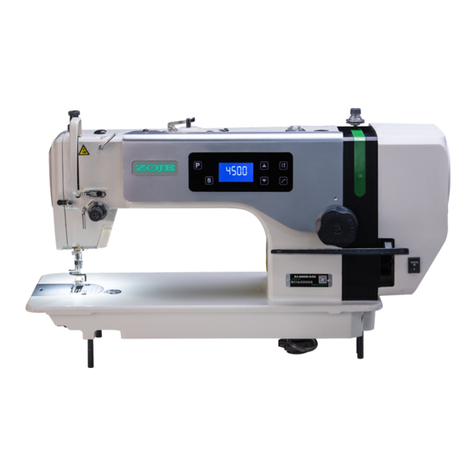
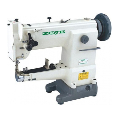
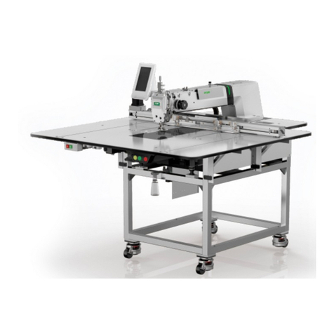
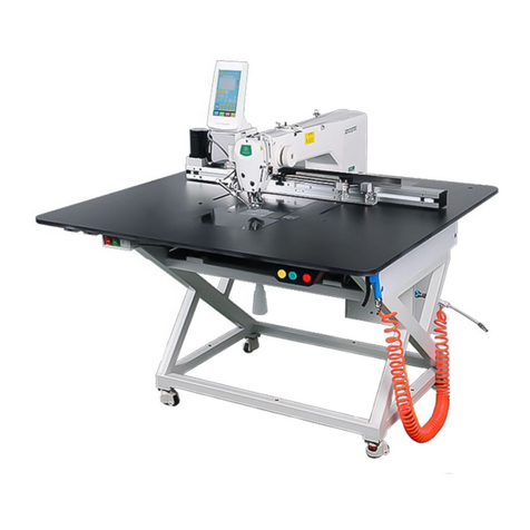
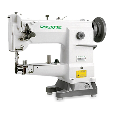
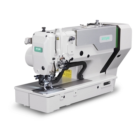
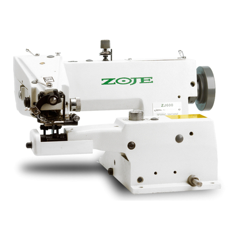
ZOJE ZJ9800 User manual

4'
is
E
‘*
fi$
%*fl
ZJQBOOgW
ZC-EDJ'E
III
I:
HIGH-SPEED
LOCKSTITCH
SEWING
MACHINE
{Emififlflfi
31¢
¥
flfl
OPERATION
MANUAL
PARTS
BOOK
EDEI-Eflliéiimmflflfiffififlflflfil
ZOJE
SEWING
MACHINE
CO.,
LTD.

ié§§%gyj$flfifimfi5fi$mu................................................................
‘
3%fififlfi‘
i‘éfi......u...u.......
..
.......
..
.........
.......
..
nu
_
fi§gwmfilg§fi.u.uuu........
‘%fi%fi%gmfigmmmmmmmmnmmnummmnmmmom”
_fiflmgfimmmmmmmmmmmmmmmmmmmmmmmmmmm
‘m%mmmmmmmmmmmmmmuumoummmnumonmm
_
fifififim1fi%....u...u
nfim%m§(mfl)mfigfigmmmmnmmmmmum.mumnm
_
m%l‘m§3&-fiflin....u.u.......u.u..........u..........u............................
‘E®m§%fi%mmmmmmmoummmnummoummonum
_fimmfifimmmmmmmmmmmmmmmmmmmmmmmmmm
.EWEfimfifimmmmmmmmnum......H.H""m"
.fi%m$%fi%
.E§m%%fi%mmmmmmmmmmmumu"uuuuumnno
_
figg§fifigfi¥.....nnu.
nfififimfifimmmmmmmmmummmummmummmummm
_
Ehéfijqiyhégfiflaw—figuuuuuuuun...............u...............................
.mfifitmfimfigmmmmmmuuu.ummmmum..mmu
_
fifijfiflflffi’fflififigfiébfl"""""""""'"'"'"'"'""'"""”""""""""
.fifimfigmmmmmmmmmmmmmmmm""Hum...."
_fimfiwmmmmmmmmmmmmmmmmmmmmmmmmmmm
ngmfifim%mmmmmnmmmummmnmmmnmmmnmmm
.flfi+gfigmm%gumumumumu.uuu...."mnmumumnn.
_gymwfiggfimmmmmmmmmmmmmmmmmmmmmmm
_fifififimfigmmmmmmmm“mmmmmmmmmmmmmmmm
nEfl%mfigmmflgmmmmmmmmmmmmmmmmmmmmm
_fifimfigmmmmmmmmmmmmmmmmmmmmmmmmmm
.fifimmmmmmmmmmmmmmmmmmmmmmmmmmmmm
ofiggwfiflmmmmmmmmmmmmmmmmmmmmmmmmm
'
figfimflgwfikfifififii$rfiinnu.......................................nun...
\DOOHJQU‘I-Ibb-JNH
WWMNMNMNMNMN—p—u—p——I——p——I—n
HOCOOMJCNm-b-WNFONDOOHJCNLfl-PWNFO
640.0.4r-LMICJH
wwmmmmmmmmmHHH_——p—n—HLHH
HOkom~datnktflmrd©\9m~J04:&DJHCDQC

CONTENTS
Before
Operation
1.
Specification3m--m-
2,
Installation.................................................................................
-
Adjusting
the
height
of
the
knee
lifteru-m-v-mu
.. ..
.
Installing
the
thread
stand
_
LUbrICation”"“"‘
can. a...
one.
.
Adjusting
the
amount
of
oil(oil
splashes)
in
the
hook
.
Attaching
the
needle-
3
4
5
6-
Adjusting
the
amount
of
oil
in
the
hook
7
8
9
.
Setting
the
bobbin
into
the
bobbin
case
..
-
]0_
Adjusting
the
stitch
length
11_
Presser
feet
pressurem
..
]2_
Threading
the
machine
head
13_
Winding
the
bobbin
thread-ummmu
..
14'
Thread
teneton
15.
Thread
take-up
qpnng
.. ..
..
.. ..
]6_
Adjusting
the
thread
take-up
stroke-
17.
Adjusting
the
needle
stop
position-"mm-H"
. .
18.
Oil
cheak
and
addltlon
19.
Adjusting
0f
the
pedal..................................................................
20
Pedal
operatton
21.
One-touch
reverse
stitching
mechanism-"m-m-n-
22.W1per
23.
Needle-to-hook
relationship---
24'
Change
of
counter
kmfe
25.
Change
of
counter
knife
and
moving
knife
26.
Adjustment
oftrimming
system------------------------------------------------------
27-Height
and
tilt
of
the
feed
dog
28.AdeStlng
the
feed
timingo-utuooott
noouuoouuoooo-uu
noun: ounc- Outtt
assumes...
no.
29.
Thread
tension
release
releasing
mechanism"---------------------------.---...
30.
Micro-lifting
mechanism
of
the
presser
foot
31.
Caution
when
carrying
or
placing
the
sewing
machine-mun-nun-um...

Eififififlfllfifififi$lfi
Efi:fiTWiflfiWfiEfifififlfi,fifiuMFfiHD
>ifiifil
lifiélll‘JLl‘JLfi'hqififlflfiiEtfi
(élé)
n
>fim2fifi~fiflflfi¢flfia
>fififimfiflfl2fi,fiflmfififl¥$u
>aaeaa¢anma¢.#mn.
>fififl$$fififlfi£fin
>eaaaaaaaamnae.
>emna$nw,ean$aam.
>aaaamaaannefinaama.
>fi$¥flfiflflflflfi.flfififififi%$fio
>aaaaaanmaana$aaamaamaitaa,eaaamw.awn
W&fi%%flfififififlfi$fifi%n
BEFORE
OPERATION
Caution:
To
avoid
malfunction
and
damage
of
the
machine,
confirm
the
following.
>
Remove
air-vent
cap
(red color)
attached
to
the
sewing
machine
bed.
>
Be
sure
to
pour
in
the
oil
before
using.
‘P
Before
you
put
the
machine
into
operation
for
the
first
time
after
the
set-up
,
clean
it
thoroughly.
>
Remove
all
dust
gathering
during
transportation
and
oil
it
well.
)>
Confirm
that
the
voltage
has
been
correctly
set.
>
Confirm
that
the
power
plug
has
been
properly
connected
to
the
power
supply.
>
Never
use
the
machine
in
the
state
where
the
voltage
type
is
different
from
the
designated
one.
)>
Confirm
that
the
direction
of
rotation
of
the
motor
pulley
is
correct.
>
Do
not
tilt
the
sewing
machine
head toward
this
side
since
oil
leakage
or
parts
breakage
occurs.
A
safety
switch
is
installed
so
that
the
sewing
machine
cannot
be
operated with
the
head
tilted.
When
operation
the
sewing
machine,
turn
On
the
power
switch
after
properly
setting
the
head
on
the
table.

1.j3¥fi/Rfill%.
gift
H1535
fififi'fli
ternater
DB><19#~18#
DP
x5
16#~18#
$fi18mm
(WE)
lޣEl5mm
(EX)
ZJ
1
E'flLirfi
1.
Specifications
Application
Thin-medium
material
Heavy
material
Sewing
speed
5000mm
61000er
Stitch
length
Needle
DP X5
lfi‘hulgl't
By
hand
lifter
18
mm
(standard)
Presser
foot
lift
By
knee
lifter
15mm
(max.)
Oil
Rated
power
2-
fiéflfltfi’mfi
Installation
l-flfifitfi%
1)
idifitifitfir’t‘fifiiifiglflllfifllffii;
2)
MRfifiiE®H§flfifitE¥f®lfilifiA#fl
(iiifiii'efiifi#ifl).
fifiHflhfiEifiGflfifififl
flare)
EEEB—‘i’l
(%$fl%i§fi%fiifi%—-fl)
fifilfiiflliifliflfifis
3)
Ell
NEH)?
kEI‘JJ'ifiIEtfi@D
(lfiifiwLa‘kHa‘,
ifi#ffiiflfik€§§©fiit)

bamaaaaonaaaaaa.seu
amafiaaaomaeanmaaan
EMREWH%E§®ED
aa=uararaaaoeaaaa.a
anuuanaommo
1‘
Installing
the
oil
pan;
1)
The
oil
pan
should
rest
on
the
four corners
of
the
machine
table
groove;
2)
Two
rubber
seats
®
for
supporting
the
head
portion
on
the
operator
side
®
are
fixed
on
the
extended
portion
of
the
table
by
hitting
the
nails
CD,
and
the
other
two
rubber
cushion
seats®
on
the
hinged
side
®
are
fixed
by
using
a
rubber—based
adhesive.
Then,
oil
pan
@
is
placed;
Remove
air
vent
cap
(5)
attached
to
the
machine
bed.
(Be
sure
to
attach
cap
when
transporting
the
machine
head
in
the
state
that
the
machine
head
is
removed
from
the
machine
table.)
Fit
hinge
into
the
opening
in
the
machine
bed,
and
fit
the
machine
head
to
table
rubber
hinge
@before
placing
the
machine
head
on
cushions
(3)
on
the
four
corners.
Caution:
It”
the
sewing
machine
is
operated
without
removing
air
vent
cap
6),
oil
leakage
from
gearbox
portion
G)
may
occur.

3.
maiafiaemaa
Adjusting
the
height
of
the
knee
lifter
ZQXWE:Wrmtfimmwgfiflfl.%%fi%%ZEfifififlfie
Warning:
Turn
OFF
the
power
before
starting
the
work
so
as to
prevent
accidents
caused by
abrupt
start
of
the
sewing
machine.
1.ME%WWfiEEWEEEW
§*:
2.m%&fi§fifi©nuflna
Wfifiifikfléfi%*:
EfizfiEW%flEflw§*W
fifi§éfi$flfl,flfififl®
5EW®§mma
l,
The
standard
height
of
the
presser
foot
lifted
using
the
knee
lifter
is
10mm.
2.
You
can
adjust
the
presser
foot
lift
up
to
l5mm
using
knee
lifter
adjust
screw
@.
Caution:
Do
not
operate
the
sewing
machine
state
that
the
presser
foot
@is
lifter
10mm
or
more
since
the
needle
bar
®
in
contact
with
the
presser
foot
®l
4
.
fififififi§§
Installing
the
thread
stand
1.Wflfi$%fi&%§%fl%%mfififl
Lu
2.m&i%fi®fififi%u
3.nanan,emenauamn®e
gun
I .
Assemble
the
thread
stand
unit,
and
insert
it
in
the
hole
in
the
machine
table.
2.
Tighten
locknut
(D
to
fix
the
thread
stand.
3.
For
ceiling
wiring,
pass
the
power
cord
through
spool
rest
rod
®.

5.
With
Lubrication
A
iii-2.1%:
fiTfiiffiéflmfi'flfié’l‘flfiJ,
ifiééifitEflEZlfififliffiéi’Ea
Warning:
Turn
OFF
the
power
before
starting
the
work
so
as to
prevent
accidents
caused
by
abrupt
start
of
the
sewing
machine.
fifi‘fiéfll‘flzm,
ifi—‘Eiflfil‘fi
Mifihwlflffii
l.
iflfiiéfllmlfifil.
fikfilifl9<§i
gift.)
-
Ell
I‘Allflr‘flililfl'flfi'iCD.
fiffll‘fiifi‘
fiijflfliflifi'fiflflAZJ
lemma.
.
ififflflhhnffiiflflflififififi'flfifléfiifi
fin
ififififlflflfifigfl'flifi.
iJL
%%M%%$%¥Lififl5§.
iii.
fifliizifififliii‘ffiufliflfl'fliflfio
fiflfiengrmed
.
{Effifiééfimfii
fiufiflfifii'fii‘
marker
line
fl:
®
*5
Eu
ill}
E
1:57?"
Ei-
@
Fig—F
all
éElrLl—F,
ifiilii'I—llllfliio
$5M?
Lower
engraved
Engraved
markerline
355.1%:
"WWW“
1.enaeemnanenaa
enneann,eaafimm
~3sooeraemeaeaz
enen.
2.
ififl‘lfiilfltfifis’éfifififiifiu
Fill
the
oil
tank
with
oil
for
hook
lubrication
before
the
sewing
machine.
1)
Tilt
the
machine
head
until
it
comes
in
contact
with
the
head
support
rod.
2)
Remove
oil
hole
cap
@and
fill
the
oil
tank
with
2]
No.1
using
the
oiler
supplied
with
the
machine.
3)
The amount
of
oil
should
reach
up
to
the
engraved
marker
line
of
oil
tank®.
If
the
oil
is
filled
excessively,
it
will
leak
from
the
air
vent
hole
in
the
oil
tank
or
proper
lubrication
will
be
not
performed.
So
,
be
careful.
4)
When
you
operate
the
sewing
machine,
refill
oil
if
the
top
end
of
oil
amount
indicating
rod®comes
down
to
the
lower
engraved
marker
line
of
oil
amount
indicating
rod
comes
down
to
the
lower
engraved
marker
line
of
oil
amount
indicating
window@.
_5_

{Caution}
LWhen
ytm
use
:t
he-e-
sewing
machine
or
:t
gnawing
machine
after
an:
cxltfilldcd
pat'iud
ttl~
disuse.
run
fmur
machine
all
3.flfl{}ffl
ELSUUrpm
[In
the
purpnse
m'
break-tn
2.
lJn
11m
tetnm-e
ruhhet
pingi-
fi.
hittfihhifltflififi'fl’fit
(HUI!:Pfifihi-flthltfiHJL-fle)
Adjusting
the
mutant
hf
nil
in
the
hunk
A
tlifll:
54's:TFDIILfithLFHJEFFEfiL
iffs'ét‘iililflEzhfil'fiiiHHEtEfiin
Warning:
"IFtIrn
OFF
the
putter
hel‘ure
shutting
the
wnrk
5n
:1}:
tr:
prevent
accidents
CitLlSfld
by
abrupt
Marl
uJ'
Lhr:
eventing
machine.
HE he
flirt};
HI
1513
hi
fih
'iii'fl'll
Ti
5‘34.
”f
I
fl‘l
3F:
11%]
'I'J'
a
1.Mhflfl:
EFF
11%":
1:
IFIJ
Ettriftll
REE-E
fish
litilu'rl't‘iflh
Hi‘DJfi,
Ifitfiflhflfi$
ti‘fi
[II‘IJJEH'
an
Ethan
fiffléflh
Witt}
.l.
it't'tit‘ezfltfih
EtfiiéflfiltflleRPflEhE
Philliemll
H-I'.
Et't
--m+mr:hh1§tllhxl~,
$114:
chllfifitt'
a
2-
{SEFHHI’KHE
(T‘I‘Cfiflftfil
flit
,
-ELI
*firfih‘fitflfltfih
H—Hfilflhfltti
n
Adjtlfilmtnt
tJf'
the
Etmuutll
t‘ri'
oil
it]
the
IJtJ-nk
i5“
pet'fut'tned
with
hi]
Etmmn'tt
{lEleLHllTlL‘l'll
fierew
.1)
1.
Adiheunenl
pthcethlre
Tighten
{tum
clockwiege]
nil
ammtnt
atljtmtment
screw
I1];-
tn
increase
the
muuunt
hf
011
in
the
hunt:
tar
Ihheen
{turn
muttteretnckwtse}
In
decrease
il.
{Cattllhm}
|.1r"r'hefl
using
RP!mhk[l1uukl‘ur
dry
head]
fur
the
HE
13r1te1he
.‘iLll't't
te
lumen
Lhr:
nil
:nuetmt
mtjuxtment
screw
up
In
1he
minimum
at:
as;
to
reduce
the
oil
anmunL
in
the
hunk.
2.
Never
drain
the
hi!
in
the
hi1
tank
even
when
RP
hook
{hank
1hr
dry
head}
is
nae-t1.

7.fi§%fl%(flfl)%fi¥fifi
Adjusting
the
amount
of
oil
(oil
splashes)
in
the
hook
[c3
ea:aaecaeaan.aroeaeea.aanea,amanenne.
Warning:
Be
extremely
careful
about
the
operation
of
the
machine
since
the
A
amount
of
oil
has
to
be
checked
by
turning
the
hook
at a
high
speed.
CD
Amount
of
oil(oil
splashes)
confirmation
paper
G)
Position
to
confirm
the
amount
of
oiltoii
aplashes)
CD
ifliilifliifilfiflfifiéfi
Q“,-
idiifiifiii‘fliifiikiifi
Hook
..
fiffi
Hook
firming
Shaft
front
Approx
25
mm
25mm
2.23
3
to
10
mm
L—J
Approx.70
mm
Oil
splashes
confirmation
paper
Closely
fil
lht‘
Paper
i’Dmm
ZEE
ifiifififlfiffigfi
against
the
wail
surface
of
the
bed.
Tiiilitltlélifl‘liiffii
*
Use
any
paper
available
regardless
of
the
material.
‘
Place
the
amount
of
oil
(oil
splashes)
co
9%
JFFH
ilfigfififllfifio
paper
under
the
hook.
X
i’EflifiiifliiflEi
fiflfiffififfiflfiflfi'l‘fiu
1.
ME
(BE)
FfiiiJUi‘il:
iEfi'lffilJZNF-Jifii’fifli.
ifiifll
I‘ifi’ili,
fifiifififififi$ififififilfifiififlfio
1)
6L%@fi]fl’ia
ifiififi3fii¢ififi9§¥§o
(ifiéifi’iliflfiiciéii‘éh
2)
fiEfifiéfllflLi‘Efith'fiifilE
(ilflfl)
fifflikfifiiéitifiko
3)
fifiiikifliifirhfifififlflo
4)
iflife‘
(no)
lifliikfla‘liflfiaif').
1.
How
to
confirm
the
amount
of
oil (oil
splashes)
When
carrying
out
the
procedure
described
below
in
2,
remove
the
slide
plate
and
take
extreme
caution
not
to
allow
your
fingers
to
come
in
contact
with
the
hook.
i)
If
the
machine
has
not
been
sufficiently
warmed
up
for
operation,
make
the
machine
run
idle
for
approximately
three
minutes.
(Moderate
intermittent
operation)
2)
Place
the
amount
of
oil
(oil
splashes)
confirmation
paper
under
the
hook
while
the
sewing
machine
is
in
operation.

3)
Confirm
that
oil
exists
in
the
oil
tank.
4)
Confirmation
of
the
amount
of
oil
should
be
completed
in five
seconds.
(Check
the
period
of
time
with
a
watch.)
2.
iflifi
(ifliiflr)
fifififi
Splashes
of
oil
from
the
hook
Rfiifixfllfiflfléfiflifll
I’
W“
—
“PEN:
0.5
~
IInm
EH:
l~
3mm
thin
and
medium
matcrialflj
In
[Him
heavy
\vcith
material:
I
In
3mm
Approprtato
amount
of
oil(small)
idiiifi'éi
(1h)
Splashes
of
oil
from
the
hook
aamxasaiaeasia
IV
flap-t
—
Illjtfiiifi:
I
»—
I
.Smm
EH:
2-w41'11111
thin
and
medium
materiam
to
1.5mm
heavy
weatlil
material:
2
m4mm
Approprtato
amount
of
oil(large)
aiifliifi
(at)
sewing
product
may
be stained
with
oil.)
Dilflfiiflfiifiééififlfifififi
fi‘tifiiififli,
{Hitifiig‘flrifiq’afi
alike
aiiéifibfli,
Qx‘Ziifit
fiiiifir‘fiifiu
iHifiitfiHT
’2?
iafikfieifiin
mite
($311313)
mamwaac
Eflfia‘fiin
.
Sample
showing
the
appropriate
amount
of
oil
The amount
of
oil
shown
in
the
samples
on
the
left
should be
finely
adjusted
in
accordance
with
sewing
processes.
Be
careful not
to
excessively
increase!
decrease
the
amount
of
oil
in
the
hook.(if
the
amount
of
oil
is
too
small,
the
hook
will
be
seized
(the
hook
will
be
hot).
If
the
amount
of
oil
is
too
much,
the
2)
Adjust
the
amount
of
oil
in
the
hook
so
that
the
oil
amount
(oil
splashes)
should
not
change
while
checking
the
oil
amount
three
times
(on
the
three
sheets
of
paper).

8.
filfififi%%jfii&
Attaching
the
needle
A
'EEfi:
fiTI‘fiifiéflJiflH’flfi'fil‘i-Efit,
ififiéifififlifiZJfifiifiiilfiéi’Fn
Warning:
Turn
OFF
the
power
before
starting
the
work
so as to
prevent
accidents
caused
by
abrupt
start
of the
sewing
machine.
isleFHDan-lzopxsfifirtttto
ifiiflfiéfififltfiafl.
miraiaasaaiaamaa.
.Efi$%,mafiaflfifi
do
.eaaaaeea@,se
tJtfi-teiittl-CDIHIsBGJifiI‘a
Efi®mfimo
.
reiteraaaaamrsa.
.saaaaaeae
.aaamea©aaam
®mfiMD
BEE:
fiffiififiiflé’fafil.
finfiflfi'filflifil’mififi.
fififiiéfifi$fi.fifiifiéfifififfl§io
ffifiififimfiéfla‘,
ifiifil‘flififiifirfilfiififlfiifi,
fifill’lfi‘flfiflfliflgfififiu
A
needle
of
DBxl
or
DPxS
should
be
used.
Select
a
proper
needle
size
according
to
the
count
of
thread
and
the
type
of
material
used.
1.
Turn
the
hand—wheel
until
the
needle
bar
reaches
the
highest
point
of
its
stroke.
2.
Loosen
screw
@,
and
hold needle
{D
with
its
indented
part
®
facing
exactly
to
the
right
in
direction
..
3. Insert the
needle
fully
into
the
hole
in
the
needle
bar
in
the
direction
of
the
arrow
until
the
end
of
hole
is
reached.
4.
Securely
tighten
screw
(2).
5.
Check
that
long
groove
©
of
the
needle
is
facing
exactly
to
the
left
in
direction
@.
Caution:
When
filament thread
is
used,
if
the
indented
part
of
the
needle
is
tilted
toward
operator's
side,
the
loop
of thread
becomes
unstable,
As
a
result,
hangnail
of thread
or
thread
breakage
may
occur.
For
the
thread
that
such
phenomenon
is
likely to
occur,
it
is
effective
to
attach
the
needle
with
its
indented
part
slightly
slanting
on
the
rear
side.

9.
mafltflfififirljfli
Setting
the
bobbin
into
the
bobbin
case
1.aaeaxa¥m;
2.aaueeimaa®mea.a®amam.
aa,annaaaraaa®aam;
3.aea©h.aenaaanaaa.
1
.
Install
the
bobbin
in
the
bobbin
case
so
that
the
thread
wound
direction
is
clockwise.
2.
Pass
the
thread
through
thread
slit
@,
and
pull
the
thread
in
direction
®.
By
so
doing,
the
thread
will
pass
under
the
tension
spring
and
come
out
from
notch
®.
3.
Check
that
the
bobbin
rotates
in
the
direction
of
the
arrow
when
thread
©
is
pulled.
10.
fiiilélilijilfl‘fi
Adjusting
the
stitch
length
1.fifififififl©fifi%fiflfifi,fififi$fi$fififlfihmflfi®;
2.fifliflflfifi$$fim%*fifis
3.aaaeaaaa.anaaaoaaaaamrnna,eaaanaa.
1.
Turn
stitch
length
dial (D
in
the
direction
of
the
arrow,
and
align
the
desired
number
to
marker
dot
03)
on
the
machine
arm.
2.
The
dial
calibration
is
in
millimeters.
3.
When
you
want
to
decrease
the
stitch
length,
turn
stitch
length
dial
6)
while
pressing
feed
lever
C2)
in
the
direction
of
the
arrow.
lie
[2:
Efi:%T%i%flmW%%Efi.fiifififlififififififio
é
Warning:
Turn
OFF
the
power
before
starting
the
work
so
as
to
prevent
accidents
caused
by
abrupt
start
of the
sewing
machine.
_10_

1.
fiflififififlfEfiWfi
(EFAJ‘J‘FI'J)
fiflfls’fifiifi‘i‘iflfl.
Efifiififi:
2.
iifl‘fif
(EIJBJ’J‘EH)
fifiiflifififi
Tififl.
Hijfilfififi:
3.
fidfiififi§fiflififl®s
4.
M—flhfifififi‘é’JifiififififiB‘lfi
fifififin-fimaflfi
(451(3)
a
l.
Loosen
nut
Q).
As
you
turn
presser
spring
regulator
(D
clockwisetfin
direction
A),
the
presser
foot
pressure
will
be
increased.
2.
As
you
turn
the
presser spring
regulator
counterclockwisefin
direction
B). the
pressure
will
be
decreased.
3.
After
adjustment,
tighten
nut
G).
4.
For
general
fabrics,
the
standard
height
of
the
presser
spring
regulator
is
32
to
34mm(4.5kg).
12.
ifiiéfifififlfififié
Threading
the
machine
head
A
33%:
fiTWmfiéfiflLWfifibflfiJ.
fifiéififififififlfilfltflfifio
Warning:
Turn
OFF
the
power
before
starting
the
work
so
as to
prevent
accidents
caused
by
abrupt
start
of
the
sewing
machine.
(mm
In:
numnss
Illis
thream
mush
mutmu
.
IE:
zeeaasaoan

B.
fi$$fi®§fi
Sign?
3:23:33
_.E$Gfi§%§§®3fl
fifi.
N.H%%m§$%fi§E§
%%%.¥Efififififi
flfififl$%$fi.fifi
fi?fifi$fl.flfi$%
fififlflgfifikfififi
Eflu#%M§fi%vo
.3fifififiQfiflGfi
EuméfigEaEGE
©fi§fi§.fi%¥fi
$$Homfiflfiflfifi
EQEQEFa
p.%fi$fi.£§%¥$fi
@gfigfia
m.fimm%%%WE.fi$$E%%fl
®.fifi$%@@§fl®fififl©
&3.¥flfififififl®o®fifl
fi%.@&EfiWa
o.§fififi$fi§$éfi.fl$$fifi
@.fi§%%%&%.fifim%&fi
95mm"
V
fifi%é§fi§bfi%éflfilfifi$§fiaflfl
V1§fifi®fi.§§fi®fi§@§m%&fififim,T%%$WEQE§E@&E
mgfifififigfifima
fififlflflfififlfl.fiflfififl®$fin
q.fififi%%§%&2.flfi§%%&fiaafimfimo
4.1mm"
_.fifififii.fififififififififi®hfimfifififlfifi$fia
m.fifimfifi2$$fififififi.flfihfiififififlfifihgfifi.fi$figfifi%
Efififlflfiio

1)
Insert the
bobbin
deep
into
the
bobbin
winder
spindle
Q)
until
it
will
go no
further.
2)
Pass
the
bobbin
thread pulled
out
from
the
spool
rested
on
the
right
side
of
the
thread
stand
following
the
order
as
shown
in
the figure
on
the
left.
Then,
wind
clockwise
the
end
of
the
bobbin
thread
on
the
bobbin
several
times.
(In
case
of
the
aluminum
bobbin,
after
winding
clockwise
the
end
of
the
bobbin
thread,
wind
counterclockwise
the
thread
coming
from
the
bobbin
thread
tension
several
times
to
wind
the
bobbin
thread
with
ease.)
Press
the
bobbin
winder
trip
latch
®
in
the
direction
of
®
and
start
the
sewing
machine.
The
bobbin
rotates
in
the
direction
of
C
and
the
bobbin
thread
is
wound
up.
The
bobbin
winder
spindle
(I)
automatically
as
soon
as
the
winding
is
finished.
Remove
the
bobbin
and
cut the
bobbin
thread
with
the
thread
cut
retainer
(33.
To
adjust
the
winding
amount
of
the
bobbin
thread,
loosen
the
setscrew
GD
and
move
the
bobbin winder
adjusting
plate
6)
to
the
direction
of
®
or
..
Then,
tighten
the
setscrew
6).
To
the
direction
of
®:
Decrease;
to
the
direction
of
©:
Increase.
In
case
that
the
bobbin
thread
is
not
wound
evenly
on
the
bobbin,
loosen
the
nut
©
and
turn
the
bobbin
thread
tension
to
adjust the
height
of
the
thread
tension
disk
CD.
It
is
the
standard
that
the
center
of
the
bobbin
is
as
high
as
the
center
of
the
thread
tension
disk.
Move
the
position
of
the
thread
tension
disk
CD
to
the
direction
of
®
as
shown
in
the
figure
on
the
left
when
the
winding
amount
of
the
bobbin
thread
on
the
lower
part
of
the
bobbin
is
excessive
and
to
the
direction
of
®
as
shown
in
the
figure
on
the
left
when
the
winding
amount
of
the
bobbin
thread
on
the
upper
part
of
the
bobbin
is
excessive.
After
the
adjustment,
tighten
the
nut
(E).
7)
To
adjust
the
tension
of
the
bobbin
winder,
turn
the
thread
tension
nut
..
Caution:
I.
when
winding
the
bobbin
thread,
start
the
winding
in
the
state
that
the
thread
between
the
bobbin
and
thread
tension
disk
("D
is
tense.
.
When
winding
the
bobbin
thread
in
the
state
that
wing
is
not
performed,
remove
the
needle
thread
from
the
thread
path
of
thread
take-up
and
remove
the
bobbin
from
the
hook.

14.
fig’fiflfiflfifiiflfi
Thread
tension
1.
fiéfifi‘lfififlififilifi
1)mneaneeonnaam
(@MWfifi.fifiMWfi§
GE;
2)flfi%fiflfifl®fifififim
(@fifl)%fi,fi%%%fi
§E§
3)flfi%fififi®flfi©fiflfi
fi.fifififl§fii
4)M%%fififl®fl£®fiflfi
n,neanee.
2Efi%flmfi¥
l)m%%fififi®flfi®%fiflfifi.Efi%h§fi:
2)nE®nnnanmae.
l.
Adjusting
the
needle
thread
tension
1)
As
you
turn
thread tension
nut
(D
clockwise
(in
direction
®),
the
thread
remaining
on
the
needle
after
thread
trimming
will
be
shorter.
2)
As
you
turn
nut
(D
counterclockwise
(in
direction
O},
the
thread length
will
be
longer.
3)
As
you
turn
thread
tension
nut
®
clockwise
(in
direction
©),
the
needle
thread
tension
will
be
increased.
4)
As
you
turn
nut
®
counterclockwise
(in
direction
®).
the
needle
thread
tension
will
be
decreased.
2.
Adjusting
the
bobbin
thread
tension
1)
AS
you
turn
tension
adjust
screw
6)
clockwise
(in
direction
®),
the
bobbin
thread
tension
will
be
increased.
2)
As
you
turn
screw
(":3
counterclockwise
(in
direction
(E),
the
bobbin
thread
tension
will
be
decreased.
15.
ybgfififififlfififi‘
Thread
take-up
spring
I.%fi%%fi§%fifi:
llfiflfiflfifi®;
2)neeen®amwann(n®fih)ann,aeamaneeek;

esseeesemsem
(W®fifl)fififi.%%
smsesseoo
.nssenmse:
fiflflfififi®.fl$%fi
fi©(§fi)s
fiflfifififl@,#fifi%
fififi®s
esseeeemnsfin
(W®fifi)%fiw,%%%%%fififik:
4)mesee@sseeen(ween)sme,essmefieeeo
flfiamfifimrfi,fifififlflfifififiuHEEfifififiWfiHfi§fiWfififi,
4fi¥fi%flfififls
'
esseesnsssjaeiss,
fififil
-
#Eéfiss—efiiebftiwfiefifi
fiJ’i’PifiEEFQEM
9
Wilmfiié
.
The
thread
take-up
spring
a
When
the
thread
take-up
spring
moves
up
to
works
up
to
the
last.
midway,
thread
is
fed out
from
0
since
the
tension
of
the
thread
take-up
spring
is
high.
sseneesmnese=nusssmsnneefi,eesm®emee,n
fiEfifififlfififififiZfififi®flflfififi.fififififififififla
1.
Changing
the
stroke
of
thread
take-up
spring
1)
Loosen
setscrew
Q).
2)
As
you
turn
tension
post
(3)
clockwise(in
direction
®),
the
stroke
of
the
thread
take—up
spring
will
be
increased.
3)
As
you
turn
tension
post
6)
counterclockwisefin
direction
.),
the
stroke
wiil
be
decreased]
2.
Changing
the
pressure of
thread
take—up
spring
(D
1)
Loosen
setscrew
(23.
and
remove
thread
tension
6).
2)
Loosen
setscrew
G).
3)
As
you
turn
tension
post
(3
clockwise(in
direction
®).
the
pressure
will
be
increased.

4)
As
you
turn
tension
post
(33
counterclockwise(in
direction
O),
the
pressure
will
be
decreased.
Usually,
upon
the
machine
coming
out,
all
the
take-up
spring
has
been
adjusted
well,
only
while
sew
special
material
thread,
it
need
to
be
adjusted
again.
To
judge
the
work
of
the
thread
take—up
spring,
confirm
whether
or
not
the
thread
take—up
spring
works
up
to
the
last
before
needle
thread
is
pulled
out
from
®
when
pulling out
needle
thread
in
the
direction
of
Oafter
the
pressure
of
the
thread
take-up
spring
has
been
performed.
When
it
does
not
work
up
to
the
last,
decrease
the
pressure
of
the
thread
take—up
Spring.
In
addition, the
stroke
of
the
thread
take-up
Spring
is
excessively
small,
the
Spring
does
not
work
properly.
For
the
general
fabrics,
a
stroke
of
10
to
13
mm
is
proper.
16.
flhgfiilifibgfififlfiflfiiii
Adjusting
the
thread
take-up
stroke
[23‘E§:%T%i%flmfififlflfi,fififi$fi2fifififififio
f
Warning:
Turn
OFF
the
power
before
starting
the
work
so as
to
prevent
accidents
caused
by
abrupt
start
of
the
sewing
machine.
Lfifififiw,fififi%%®flfifi
n®aa.uexaaa;
zaanaa,naaaa@aaa
fi®fifi.flfi$%fi%a
i5fifi®ififlfi©fififl¢fim
fiwhfififlfi.
.
When
sewing
heavy—
weight
materials,
move
thread
guide
Q) to
the
left
(in
direction
®)
to
increase
the
length
of
thread pulled
out
by
the
thread
take-up.
.
When
sewing
light—weight
materials,
move
thread
guide
(D to
the
right
(in
direction
O)
to
decrease
the
length
of
thread pulled
out
by
the
thread
take-up.
.
Normally,
thread
guide
®
is
positioned
in
a
way
that
marker
line
©
is
aligned with
the
center
of
the
screw.

17.
HLfi-{éflfijfififlljflfifi
Adjusting
the
needle
stop position
A
as
WTIWI.I1§§9HJLH’JE5’I‘E3L
esseazssaeae.
Warning:
Turn
OFF
the
power
before
starting
the
work
so
as
to
prevent
accidents
caused
by
abrupt
start
of the
sewing
machine.
LWfifiWfimfifi
1)semaaseeaeea
seawaA®aseaa
flfi®mfiwmfifi:
2)eaahaaesmemm
E,Efiflfifiw%fififi
fifio
>m©msnsa.maeeeag
>W®Wflflfifl,m%@ififl;
1.
Stop
position
after
thread
trimming
l)
The
standard
needle
stop
position
is
obtained
by
aligning
marker
dot
®
on
the
pulley
cover
with
white
marker
dot
®
on
the
hand—wheel.
2)
Stop
the
needle
in
its
highest
position,
loosen
screw
{D to
perform
adjustment
within
the
slot
of
the
screw.
>
The
needle
stop
timing
is
advanced
if
you
move
the
screw
in
direction
©.
>
The
needle
stop
timing
is
delayed
if
you
move
the
screw
in
direction
6:).
lfiflfi%$
1)aaanaaaaeammmareenaanames.anaereeza.fi
safimwmwsafiwa.W®ameamasmaaah.moamsamae
2.
Lower
stop
position
I}
The
lower
needle
stop
position
when
the
pedal
is
returned
to
the
neutral
position
after
the
front
part
of
the
pedal
is
depressed
can
be
adjusted
as
follows:
Stop
needle
6)
in
its
lowest
position.
Loosen
screw
(2?).
and
make
adjustment
within
the
slot
of
the
screw.
Moving
the
screw
in
direction
®
advances
the
needle
slop
timing.
Moving
the
screw
in
direction
®
delays
the
timing.
Other manuals for ZJ9800
2
Table of contents
Other ZOJE Sewing Machine manuals

ZOJE
ZOJE ZJ927 Series User manual

ZOJE
ZOJE ZJ2842-BD User manual

ZOJE
ZOJE ZJ-AM-5775AH User manual

ZOJE
ZOJE AM-5770A-410 User manual

ZOJE
ZOJE ZJ5600N User manual

ZOJE
ZOJE ZJ1900DSS User manual

ZOJE
ZOJE ZJ-M6-GS800-SF-V2 User manual

ZOJE
ZOJE ZJ9600 User manual

ZOJE
ZOJE A9200L-D4-W-CP User manual

ZOJE
ZOJE ZJ-E007 User manual