Superior MIRELLA Parts list manual

INSTRUCTIONS FOR
INSTALLATION, USE AND
MAINTENANCE
Pellet Stove MIRELLA
SUPERIOR
®
The instruction manual is an integral part of the product.

2
SUPERIOR
®
English
Dear client,
We thank you for choosing one of our products, the result of technological expertise and continued research in pursuit of a superior prod-
uct in terms of safety, reliability and features.
Inthis manual you will find all the information and useful advice necessary to get the most out of your appliance in total safety.
DT2010001-00
IMPORTANT INFORMATION DT2010208-02
REFERENCE STANDARDS DT2010209-00
The assembly of the cover should be undertaken by two people (follow the assembly instructions in the attached booklet).
Plans and diagrams are supplied as examples at the manufacturer’s discretion; in the pursuit of a policy of continuous development and innova-
tion the manufacturer may, without prior warning, make any modifications deemed appropriate.
This document is the property of Gruppo Piazzetta S.p.A.; it may not be divulged in part or in whole to third parties without written permission from
Gruppo Piazzetta S.p.A. Gruppo Piazzetta S.p.A. reserves all its statutory rights.
•This manual has been prepared by the manufacturer and constitutes an integral part
of the product, and must accompany it throughout its life. In the event of sale or relo-
cation of the product make sure this booklet accompanies it, since the information
contained in it is addressed to the purchaser and to anyone involved in the installa-
tion, use and maintenance of the product.
• Read the instructions and the technical information contained in this manual care-
fully, before proceeding with installation, use or any repairs.
• The observance of the instructions and technical information in this manual guaran-
tees the safety of the user and the product, a more efficient operation and an
increased lifespan.
• The product’s installation and use should conform to the manufacturer’s instructions
and to local bylaws.
• However, when carrying out any operation we recommend that you follow carefully
the instructions contained in this manual, and that you keep it at your disposal.
• Installation, electrical connection, checks, maintenance and repairs are operations
which must be carried out exclusively by qualified and authorised personal with spe-
cialised knowledge of the product.
•Before installing the product read all instruction booklets relating to installation of the
cladding, the ventilation kit and any other accessories.
•Be verycareful when moving anyceramic components.
•Check thatthe floor where the product is to be installed is exactly level.
• To help correct potential unevenness and irregularities a sheet of adhesive fibreglass
accompanies the product.
• Do not block the electrical socket; it should be close to the unit but accessible.
•Connect the pellet stove to the electricity supply only after it has been connected by
an expert to the flue system.
• The plug at the end of the power supply cable must be easily accessible after instal-
lation.
• Use only regulation wood pellets (refer to section entitled “Technical charateristics
and specifications” ).
•Never use liquid fuels to light the stove or to relight the embers.
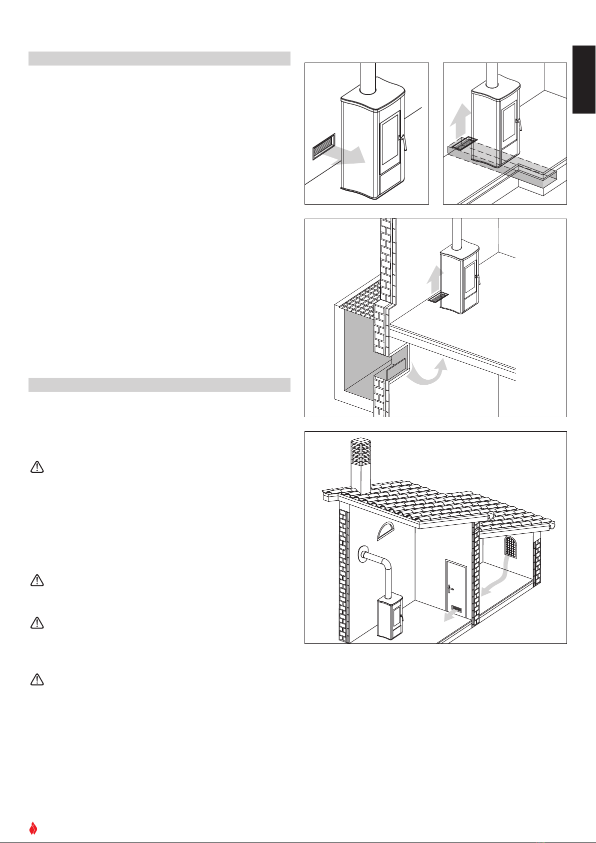
• Ensure that the area where the stove is installed is properly ventilated while the stove
is lit.
• In the event of technical faults the fuel supply will be interrupted. Restart the stove
only after having eliminated the cause of the fault.
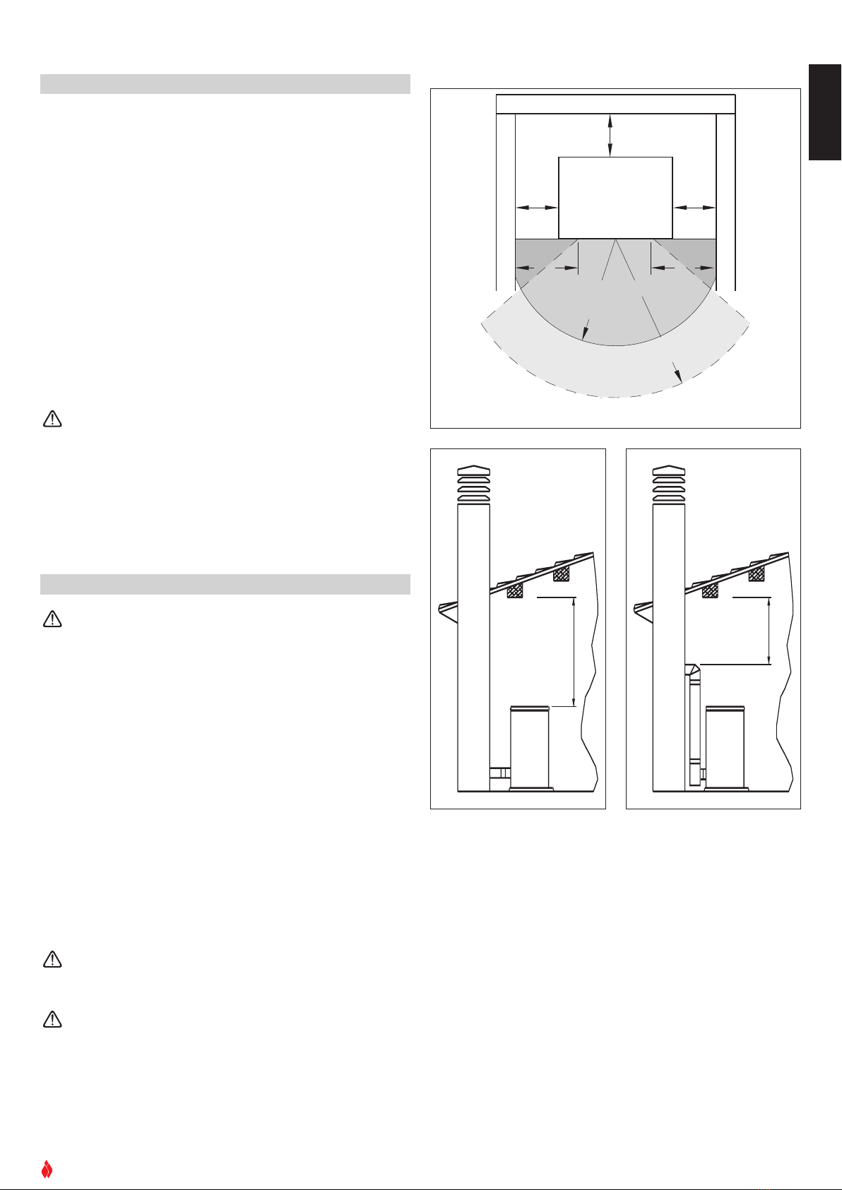
• The wall where the product is to be placed should not be of wood or any other flam-
mable material; furthermore it is important to maintain safety distances (refer to sec-
tion entitled ‘Prevention of domestic fires’ contained in the stove’s manual for use
and maintenance).
• Do not remove the protective grille from the fuel storage tank.
• Any build-up of unused pellets in the burner left over from repeated failed ignitions
must be removed before lighting the stove.
• The operation of the stove can cause surfaces, handles, flue system and glass to
become extremely hot. Touch these parts during operation only with protective cloth-
ing or other specialised equipment.
• Because of the build-up of heat on the glass, take care that those who are unaware
of the workings of the stove do not delay in the installation area.
•Keep children informed of safety measures to be followed when the stove is opera-
tional and atother times.
In the event of difficulties or if you are unable to understand the instruc-
tion manual contact your local Piazzetta dealer.
It is forbidden to place objects which are not heat-resistant on top of the
stove or within the prescribed minimum safety zone.
It is forbidden to open the door while the stove is in operation or to oper-
ate the stove when the glass is broken.
DIN 18894 Solid fuel stoves and fireplaces - Pellet-fired stoves - Requirements, testing and marking
UNI 10344 Heating of buildings. Calculation of energy requirements
UNI 10683 Wood-fired heat generators, Installation requirements
UNI 10847 Single flue systems for liquid and solid fuel generators - Maintenance and control - Guidelines and
procedures
UNI 7129 Gas installations for domestic use fired by mains gas supply
DIN 51731 class HP2 Fuels

SUPERIOR
®
English
3
INDEX
DT2010187-00
Section Title Page Code
1.0 General rules 4 DT2010216-02
1.1 Single flueway or chimney 5 DT2010024-00
1.2 Soot inspection 5 DT2010031-00
1.3 Chimney stack 6 DT2010025-00
1.4 Fresh air intake 7 DT2010026-00
1.5 Installation environment 7 DT2010215-00
1.6 Capacity load of the floor 8 DT2010032-00
1.7 Heating capacità 8 DT2010130-00
1.8 Minimum safety distances 9 DT2010224-02
1.9 Flue system 9 DT2010229-01
1.10 Connecting to a conventional chimney 11 DT2010230-00
1.11 Using external flue ducts 12 DT2010232-00
1.12 Prevention of domestic fires 12 DT2010027-00
2.0 Technical characteristics and specifications 13 DT2010102-01
2.1 Technical data 13 DT2010103-01
2.2 Plan 13 DT2030134-00
2.3 Product identification data 14 DT2010041-00
2.4 Electrical diagram 14 DT2030072-00
3.0 Fuel 15 DT2010233-00
4.0 Before unpacking your product 15 DT2010074-00
5.0 Installation 16 DT2010075-00
5.1 Electrical connection and the temperature sensor 16 DT2010078-00
5.2 Installing the external thermostat 17 DT2010079-00
6.0 Use 17 DT2010080-01
6.1 Control panel 18 DT2010081-00
6.2 Startup 18 DT2010082-00
6.3 Startup and normal operation 19 DT2010083-01
6.4 Remote control 23 DT2010084-00
6.5 Timer 23 DT2010085-00
6.6 Safety features 29 DT2010086-00
6.7 Opening the door 32 DT2010087-01
6.8 Removing the ash 32 DT2010049-00
7.0 Maintenance 33 DT2010111-01
7.1 Cleaning the burner and the burner support33 DT2010089-01
7.2 Cleaning the ash drawer 33 DT2010100-00
7.3 Cleaning the combustion chamber 33 DT2010090-00
7.4 Cleaning the smoke chamber 34 DT2010091-00
7.5 Cleaning the exhaust system 34 DT2010092-00
7.6 Cleaning the ceramic cover 34 DT2010059-00
7.7 Cleaning the metal parts 34 DT2010061-00
7.8 Cleaning the window 34 DT2010062-00
7.9 Replacing the window 35 DT2010093-00
7.10 Replacing the remote control battery 35 DT2010094-00
7.11 Cleaning the fans 35 DT2010095-00
7.12 When not in use 35 DT2010096-00
7.13 Extraordinary maintenance 35 DT2010097-00
8.0 Troubleshooting 36 DT2010098-01
Declaration of conformity 39 DT2010101-00
This booklet code H07010500 / DT2000009 - Rev. 02 (04/2005) comprises 40 pages.

4
SUPERIOR
®
English
COMIGNOLO
CANNA
FUMARIA
COLLEGAMENTO
ALLA CANNA FUMARIA
ISPEZIONE PER
RACCOLTA FULIGGINE
PRESA D'ARIA ESTERNA
VERIFICA
PORTATA SOLAIO
DISTANZE DI SICUREZZA
RACCORDO CON ISPEZIONE
1.0 GENERAL RULES DT2010216-02
DT2030321-00
Ensure that the installation of your product conforms to all the following instructions.
Fig. 1
CHIMNEY STACK
SINGLE FLUEWAY
OR CHIMNEY
FLUE SYSTEM
SOOT INSPECTION
FRESH AIR INTAKE
MINIMUM SAFETY DISTANCES
CAPACITY LOAD
OF THE FLOOR
END ELBOW WITH
INSPECTION WINDOW

SUPERIOR
®
English
5
NO
N
X
Minimo 3,5 m
MAX 45°
NO
X
1.1 Single flueway or chimney - Fig. 2÷6
Every appliance must have a vertical flue pipe operating by natural
draught to discharge the combustion gases outdoors.
The flue must:
-comply with regulations in force in the place of installation of the
appliance;
-be tight to the products of combustion, waterproof, suitably insulated,
made with materials resistant to the corrosion of the gases and to
stress;
- be connected to just one stove, fireplace or extraction hood;
- be properly sized, with constant free internal section, equal to or
greater than the diameter of the flue pipe of the stove and at least 3.5
min length;
- be mainly in a vertical position with a deflection from the axis of no
more than 45° (Fig. 2);
- be at a suitable distance from combustible or flammable materials,
ensured by an air gap or suitable insulating material;
- be of uniform internal section, preferably round. Square or rectangu-
lar sections must have rounded corners with a radius of at least
20mm and a maximum ratio between the sides of 1.5 (Fig. 4). The
walls must be smooth if possible and without narrowing. Bends must
be regular and without discontinuity (Fig. 3 - 4 - 5).
It is forbidden to make fixed or mobile apertures on the flue
pipe to connect appliances other than the one to which it is
already connected.
It is forbidden to pass other air ducts or service pipes inside
the flue pipe, however large it is.
If the flue pipe is an incorrect size or installed other than in
compliance with the above instructions, Gruppo Piazzetta
S.p.A. cannot be held liable for malfunctioning of the product,
damage to property or injury to persons or animals.
1.2 Soot inspection - Fig. 1
-The flue must have a chamber for collecting solid matter and any
condensate located below the connection and which may be easily
inspected by means of an airtight door. (Fig.1)
- The bends connecting to the flue must have inspection points that
allowthe system to be checked, cleaned and maintained.
Ø
DT2030050-00
DT2030049-00
Fig. 3
P
R (min. 20)
L ( 1,5 x P)
Accumulo di Creosoto
DT2030189-00
Fig. 5
R (min. 20)
Accumulo di Creosoto
DT2030188-00
Fig. 4
Fig. 2
DT2030190-00
Fig. 6
3.5 M MINIMUM
Deposit of Creosoto
Deposit of Creosoto

6
SUPERIOR
®
English
1.3 Chimney stack - Fig. 7 ÷ 11
The flue must be fitted at the top with a device called a chimney stack,
designed to aid dispersion of the products of combustion in the atmo-
sphere.
The chimney stack must comply with the following requirements:
-
itmust have an internal section and shape the same as the flue;
-
it must have a useful outlet section of not less than twice that of the flue;
-
the part of the flue that emerges from the roof or remains in contact with the
outside (e.g. in the case of an open loft), must be covered with brick or tile ele-
ments and in any case well insulated. It must be built in such a way as to pre-
vent the penetration of rain, snow and foreign matter into the flue and to ensu-
re that in the event of winds from all directions and angle, discharge of the
combustion products is assured (chimney stack with down-draught cowl);
-
any buildings or other obstacles that are higher than the chimney stack must
not be too close to the actual stack Fig.8 - Fig.9;
-
the chimney stack must be positioned in such a way as to ensure adequate
dispersion and dilution of the products of combustion and in any case outsi-
de the reflux area.The size and shape of this area differ according to the angle
of inclination of the roof and it is therefore necessary to adopt the minimum
heights shown in Fig.10;
Example: Check the slope of the roof (column
α
), and the anticipated
distance of the chimney stack from the axis of the ridge (column A), if
the distance is greater than “A”lthe height of the chimney stack may
be read in (column H); if the distance is less than “A”the chimney stack
must rise above the ridge by 0.5 metres.
6-8 m
DT2030052-00
Fig. 9
TETTO PIANO
TETTO INCLINATO
0.50 m
0.50 m
0.50 m oltre il colmo
altezza zona di
reflusso Z
asse colmo
distanza maggiore A
α
H min.
distanza
min. uguale A
maggiore 5 m
pari o minore
5 m
pari o minore
5 m
DT2030053-00
Fig. 10
TETTO PIANO
TETTO INCLINATO
0.50 m
0.50 m
0.50 m oltre il colmo
altezza zona di
reflusso Z
asse colmo
distanza maggiore A
α
H min.
distanza
min. uguale A
maggiore 5 m
pari o minore
5 m
pari o minore
5 m
Fig. 11
Pitch of the roof Horizontal width of reflux
area from ridge axis
Minimum height of
outlet from roof
Height of reflux
area
α
αAH minimo Z
15° 1.85 m 1.00 m 0.50 m
30° 1.50 m 1.30 m 0.80 m
45° 1.30 m 2.00 m 1.50 m
60° 1.20 m 2.60 m 2.10 m
A
B*
*B equivale al
doppio di A
DT2030051-00
Fig. 7
A
B
B
DT2030191-00
Fig. 8
DT2030192-00
FLAT ROOF
5 m
or less
5 m
or less
over 5 m
SLOPING ROOF
distance more than A
distance
at least A
ridge axis
0.50 above the ridge
height of
reflux area Z
* B it is twice
of to A

SUPERIOR
®
English
7
1.4 Fresh air intake - Fig. 12÷15
The stove/fireplace must have the necessary air available to ensure
proper combustion.
- Make sure that the room in which the stove/fireplace is to be instal-
led has an air intake of at least the size indicated in the paragraph
“TECHNICAL DATA”.
-The fresh air intake may be protected by an external grille provided it
does not reduce the minimum section of the recommended airflow
and is in a position whereby it cannot be obstructed.
The air necessary for the fire may be obtained in different ways:
-Figure 12 through an external grille direct to the room of installation;
-Figure 13 with ducting through pipes direct to the room of installa-
tion, increasing the recommended minimum free cross section by at
least 15%;
-Figure 14 through a communicating hole from an adjacent room to
the place of installation: this system may only be used if the air flows
freely from the outside through fixed apertures;
-Figure 15 from an adjacent room to the place of installation, but only
if the air flows freely through apertures communicating with the out-
side.
1.5 Installation environment
The appliance should be installed in a location which allows safe and
convenient use as well as easy maintenance. If the product being
installed requires an electrical socket, the room must also be provided
with an earthed power supply in accordance with current regulations.
The installation of a wood-burning appliance in a bedroom,
bath or shower room or in any room where another heating
system not equipped with its own air supply (fireplace, stove
etc.) has already been installed is forbidden.
The room or rooms adjacent to that where the appliance is to be instal-
led must conform to the following requirements:
It must not be used as a car bay,a store for combustible mate-
rial, nor for any activity which carries a risk of fire.
It must not be pressurised relative to normal atmospheric pres-
sure as a result of the draught created by a prior installation of
an open fire or of an extractor system.
In the same location do not install two stoves, a stove and a fire-
place, a stove and a wood-burning range etc, since the draught
from one device can interfere with the draught from another.
- The use of equipment adapted for cooking food with non-extractor
hoods is permissible only in rooms to be used as kitchens.
-Equipment using gas type C is permitted (refer to regulations in force
in the place of installation).
DT2030054-00
Fig. 12
DT2030194-00
Fig. 14
DT2030195-00
Fig. 15
DT2030193-00
Fig. 13

8
SUPERIOR
®
English
Equipment using gas type B is not permitted (refer to regula-
tions in force in the place of installation).
Using the stove or flue simultaneously with shared ventilation
systems is not permitted, whether with or without extractor
fans. Similarly the use of other devices or equipment, such as
air-conditioning systems or other heating systems which use
fans to circulate air, is not permitted. These devices can cause
the atmosphere around the stove to become pressurised even
if installed in adjacent, communicating rooms.
1.6 Capacity load of the floor
Check the load-bearing capacity of the floor, referring to the weight of the
product given in the paragraph “TECHNICAL DATA”.
If the floor does not have a suitable load-bearing capacity, adequate coun-
termeasures must be taken, for example, by using a sheet metal plate to
distribute the load.
1.7 Heating capacity
Check the heating capacity of the appliance by comparing the rated power
given in the paragraph “TECHNICAL DATA” with the power required by the
environment to be heated.
The energy requirement may be calculated approximately by multiplying
the square metres of area by the height of the ceiling; the result is then
multiplied by a coefficient, which depends on the degree of insulation of
the building, that is, on internal and external factors of the dwelling:
a) Internal factors: type of window and door frames, thickness of the
insulation and walls, type of building materials, presence of stairwells,
walls with extensive glazing, high ceilings, position of the rooms to be
heated in relation to other adjacent heated or unheated rooms, …
b) External factors: geographical position, average outdoor temperatu-
re, exposure, wind speed, latitude, altitude, …
Example of approximate calculation of the energy requirement to
heat a fixed volume to 18/20° C:
The coefficient that is normally used is determined according to the real
conditions as they occur case by case.
-From 0.04 to 0.05 kW per cubic metre in a well insulated environment
- From 0.05 to 0.06 kW per cubic metre in a poorly insulated environ-
ment.
3 rooms measuring 20m2 X (H ceiling) 2.7m = 162 m3 (volume)
In an environment with a good degree of insulation, an average value
(coefficient) of 0.045 kW may be taken
162 (volume) X 0.045 (kW) = 7.3 kW necessary (6300 kcal/h)
Conversion 1kW = 860 kcal/h
Consult a heating technician or engineer for a correct check
and calculation of the requirement of the environments to be
heated (see “REFERENCE STANDARDS”).
Rated power being equal, products with the Multi-fire system
can evenly distribute heat throughout the rooms to be heated.

SUPERIOR
®
English
9
1.8 Minimum safety distances - Fig. 16÷18
With reference to the above diagram, the minimum safe distances from
heat sensitive or inflammable materials, such as load bearing and other
walls are:
A20 cm from the wall behind the stove
B60 cm from the side wall
C100 cm in the radiating area
In the case of flooring that is heat sensitive or inflammable the floor
should be protected (using for example sheets of steel plate, marble or
tiles).
The minimum distances are:
D50 cm;
E30 cm (measured from the internal corner of the door opening).
Keep any combustible product well away from the stove when it
is lit (minimum distance from the heat radiation area), for exam-
ple: wooden furniture, curtains, carpets, combustible liquids, etc.
1.9 Flue system - Fig. 19-20
The pellet stove is not the same as other stoves. The smoke is
propelled by a fan which keeps the combustion chamber pres-
surised and the entire flue system slightly pressurised. For this
reason the flue must be completely airtight and correctly instal-
led to ensure both trouble-free operation and user safety.
- The construction of the exhaust system must be undertaken by spe-
cialised personnel or firms, as outlined in the following pages.
-Installation of the flue should be completed in such a way as to gua-
rantee that periodic cleaning can be carried out without dismantling
the entire system.
- Pipes should always be sealed with silicone (not cement-based
sealants) or specially adapted washers which will retain their elastic
and resistant properties at high temepratures (250°C). These should
be attached with 3.9mm-diameter self-threading screws.
The installation of flaps or valves which might block the pas-
sage of the smoke is not permitted.
The installation of other devices (boilers, extractor hoods etc)
which might release fumes or vapours into the flue system is
not permitted.
Z
o
n
a
r
a
d
i
a
n
t
e
d
e
l
l
'
a
p
e
r
t
u
r
a
d
e
l
f
o
c
o
l
a
r
e
Parete posteriore
Protezione a pavimento
A
BB
E
D
C
STUFA
Parete laterale
Parete laterale
E
DT2030059-01
Fig. 16
MIN 40 cm
DT2030335-00
Fig. 17
MIN 40 cm
DT2030336-00
Fig. 18
Rear wall
Floor protection
Radiating zone
Side wall
Side wall
STOVE

10
SUPERIOR
®
English
Pipes and maximum usable lengths
Pipes of aluminium-clad painted steel (minimum thickness
1.5mm), stainless steel (Aisi 316) or enamelled steel (minimum
thickness 0.5mm) with a nominal diameter of 80 or 100mm (for
pipes which run inside the flue maximum diameter 150mm) can be
used.
The male-female connectors must have a minimum length of
50mm.
The diameter of the pipes used depends on the type of installation.
The stove was designed to take 80mm-diameter pipes but, as
shown in Table 1, in some cases the use of double-lined 100mm-
diameter pipes is recommended.
Losses associated with a 90° bend can be compared to those
incurred by one metre of pipe. An inspectable T-connector
can be considered equivalent to a 90° bend.
EXAMPLE: If installing a section greater than 4.5m in length with
80mm-diameter pipe, calculate the maximum usable length in the fol-
lowing ways:
-If in the section to be fitted a maximum of three 90° bends are used,
the maximum length of the section will be 4.5m.
- If in the section to be fitted a maximum of two 90° bends are used
and bearing in mind that a 90° bend can be replaced by one meter of
pipe, the maximum length of the section will be 4.5m+1m=5.5m.
-If in the section to be fitted a maximum of one 90°bend is used and
bearing in mind that a 90° bend can be replaced by one meter of
pipe, the maximum length of the section will be
4.5m+1m+1m=6.5m.
Where 100mm-diameter pipe must be used, connect it to the stove’s
exhaust outlet with a 80mm T-connector then use a 80mm-100mm
adaptor (not supplied by Piazzetta) (Fig 19).
T-connector
The use of this type of connector must allow for the collection of con-
densation mixed with suit which builds up inside the pipe. It must also
permit the periodic cleaning of the flue without the need to dismantle
the pipes.
This type of connctor can be bought at Piazzetta outlets together with
the pipes.
Outlined below is an example of a set-up which can be cleaned enti-
rely without the need to dismantle the pipes (Fig 20).
RACCORDO A T CON TAPPO
A CHIUSURA ERMETICA
RACCORDO
ø 80 > ø 100
ø 80mm
ø 100mm
DT2030337-00
Fig. 19
ISOLANTE
RACCORDO A T
RACCORDO A T
DIREZIONE
DI PULIZIA
DIREZIONE DI PULIZIA
Max 2m
(min. 3%)
DIREZIONE DI PULIZIA
DT2030338-00
Fig. 20
TABLE 1 LENGHT PIPES
TYPE OF INSTALLATION
WITH 80mm Ø PIPE WITH DOUBLE-WAL-
LED 100mm Ø PIPE
Maximum length (with three 90° bends) 4.5 m 8 m
For installations more than 1200m above sea level
- Required
Maximum number of bends 3 4
Length of horizontal sections with minimum 5% gradient
2 m 2 m
Straight reducer
ø 80 > ø 100
Tee with sealing plug
Insulating material
Tee
Tee
Direction of
cleaning
Direction of cleaning

SUPERIOR
®
English
11
1.10
Connecting to a conventional chimney - Fig. 21-22
If you wish to use an existing chimney it is strongly recommended that
you have it checked by a professional chimney-sweep to ensure that it
is completely airtight. The reason for this is that the smoke, because it
is slightly pressurised, can infiltrate any cracks in the system and esca-
pe into living spaces. If upon inspection you find that the chimney is not
completely sound, it is recommended that you insert piping made of
new material. If the existing chimney is wide enough we recommend a
pipe with a maximum diameter of 150mm. It is also recommended that
you insulate the chimney flue (Fig. 21-22).
For connection to the chimney the use of Piazzetta’s own pipes and
bends is recommended - the stove’s outlet is the right size to connect
to these.
Other types of pipe can be used, provided that they are suitable or that
the compatibility of the connecting sleeve can be verified. Bear in mind
also that pipes and bends must be constructed according to existing
regulations. In such cases however Gruppo Piazzetta S.p.A guarantees
the proper functioning of the stove only where its own equipment has
been employed in accordance with its own instructions.
The connection to the flue system must respect the 40cm minimum
safety distance from objects which are sensitive to heat and from
inflammable materials (wooden veneers, beams or ceilings etc). (See
figures 17-18)
-If the connector has to pass through partitions or walls constructed
from inflammable or heat-sensitive materials, or through weight-bea-
ring walls, you must introduce:
an insulated barrier equal to or greater than 10cm around the con-
nector using a mineral-based insulating material (rock wool, ceramic
fibre) with a nominal density greater than 80kg/m3
- If the connector has to pass through partitions or walls construc-
ted from heat-resistant materials, you must introduce:
an insulated barrier equal to or greater than 5cm around the con-
nector using a mineral-based insulating material (rock wool, cera-
mic fibre) with a nominal density greater than 80kg/m3.
-Check that the connection to the flue system has been carried out so
as to guarantee that smoke will not leak from it under the equipmen-
t’s pressurised operating conditions.
- Check that the pipe does enter too far into the flue creating a narro-
wing of the exhaust passage. Figure 22-23
Ensure that all installation work is carried out to professio-
nal standards.
COMIGNOLO
RACCORDO A T
CON CANNA FUMARIA
NON INTEGRA
INSERIMENTO DI
UN TUBO
SPORTELLI PER
ISPEZIONE
ISOLANTE
Max ø150 mm
ø 80 mm
DT2030339-00
Fig. 21
FLANGIA DI CHIUSURA
FLANGIA DI CHIUSURA ERMETICA
IN ACCIAIO INOX O ALLUMINATO
PRESA D'ARIA ESTERNA
CON GRIGLIA NON RICHIUDIBILE
DT2030340-00
Fig. 22
Insulating material
Tee
Chimney stack
Pipe insertion
With damaged flue
Inspection
windows
Closing flange
Sealing flange in stainless
steel or aluminium
Fresh air intake with
non-closable grille

12
SUPERIOR
®
English
PRESA D'ARIA ESTERNA CON
GRIGLIA NON RICHIUDIBILE
d
DT2030341-00
Fig. 23
1.11 Using external flue ducts
You can use external flue ducts only when they correspond to the follo-
wing requirements:
- Use only insulated pipes (double-lined) in stainless steel attached to
the outside wall (Fig 23).
-At the base of the duct there must be an inspection hatch to permit
periodic checks and maintenance.
-The installation must be equipped with an windproof chimney and
respect the safety distance from the high point of the roof as outlined
in the chapter entitled “GENERAL RULES”, under “Chimney top”.
Ensure that all installation work is carried out to professional
standards.
1.12 Prevention of domestic fires
The product must be installed and used in compliance with the manu-
facturer’s instructions and European and national standards as well as
local regulations.
When a flue pipe passes through a wall or a ceiling, special
installation methods must be applied (protection, thermal
insulation, distances from heat-sensitive materials, etc.) See
the paragraph “Connection to the flueway”.
-It is also recommended that all elements made of combustible or
inflammable material, such as beams, wooden furniture, curtaining,
flammable liquids, etc. be kept outside the heat radiation range of the
stove and in any case at a distance of at least 1m from the heating
block.
- For other information, see the paragraph “Safety distances” and
“Connection to the flueway”.
- The flue pipe, chimney stack, chimney and fresh air intake must
always be free of obstructions, clean and checked periodically, that is,
at least twice during the seasonal period from the lighting of the stove
and during its use. When the stove has not been used for some time
it is advisable to carry out the checks mentioned above. For further
information, consult a chimneysweep.
-Only use recommended fuels (See paragraph “Fuels”).
Fresh air intake with
non-closable grille

SUPERIOR
®
English
13
2.0 TECHNICAL CHARACTERISTICS AND SPECIFICATIONS
DT2010102-01
2.1 Technical data
• Fuel: Natural wood pellets • Length: < 30mm
•Diameter: ca. 6 - 6.5 mm
• Water content: ca. 6% - 8%.
Data obtained under laboratory conditions with pellets of heat production rated at 5kwh/kg.
2.2 Plan
(cm)
UNIT MIRELLA
Hourly fuel consumption (max/min) kg/h 1,4 / 0,75
Nominal thermal power (max/min) kW 5,5 / 2,5
Efficiency % > 80
Draught when connected to chimney Pa 10÷15
Fuel tank capacity kg / (l)15 / (23)
Electrical power supply V 230
Frequenz Hz 50
Maximum power rating W 320
Power rating (max / min) W 110 / 70
Exhaust outlet diameter cm Ø 8
Fresh air intake with minimum useful section cm2100
Weight with majolica kg 85
Packing cladding kg 95
Packing sizes (DxWxH) cm 58,5X54X119
DT2030071-00
15 7
17,5
94
43
46
Diameter Ø 8

14
SUPERIOR
®
English
2.4 Electrical diagram
2.3 Product identification data
The rating plate gives the data and ratings of the appliance.
If the rating plate is missing, has been removed or tampered with,
any installation and maintenance operations are made difficult due
to lack of product identification.
In the event of damage, please ask the Piazzetta after-sales service
centre for a copy.
Product name
Serial number
DT2030624-00
DT2030072-00
EXTERNAL
THERMOSTAT
Smoke fan
Capacitor
PILOT LIGHT
F
N
SMOKE
SMOKE
POINTS
POINTS
PILOT LIGHT
PILOT LIGHT
FUEL-LOADING CHUTE
FUEL-LOADING CHUTE
AL . 2
AL . 1
N
Fuel-loading chute
80 1
P
2
180
1
P
2
THERMOSTATS
G
N
L
POWER
THERMOELEMENT ABGASE
SMOKE SENSOR
ROOM SENSOR
Room fan
LN
FAN 2
Brown
Light blue
Blue
Black
Brown
Blue
Red
Black
Black
Light blue
Light blue
Brown
White
White
White
Weiß
Grau
Red
Red
Black
Black
Black
Yellow-green
Yellow-green
Yellow-green
Flat cable
N.A. PRESSURE SWITCH
N. C.
N. C.
32
1
2
3
4
5
6
7
8
9
10
11
12
CN2
IC10
SERIAL
DB 9
FAN 1
Display

SUPERIOR
®
English
15
3.0 FUEL
DT2010233-00
During operation, some parts of the stove (door, handle, display,
ceramic parts) can reach high temperatures. Therefore take due
precautions, above all in the presence of children, elderly and dis-
abled persons and pets.
In order to avoid accidents or damage to the product, the following
recommendations are made:
• Unpacking and installation must be carried out by at least two
people.
• Every operation involving movement of the product must be car-
ried out with the proper tools in full compliance with current safe-
ty regulations.
• The orientation of the packaged product must conform to the
directions given in the diagrams and notices on the package.
•If cables, straps or chains are used, ensure that they are able to
take the weight of the package and that they are in good condi-
tion.
• While moving the package use slow continuous movements to
avoid tearing cables, chains etc.
• To avoid toppling do not lean the package excessively.
• Do not stop in the path of loading/unloading equipment (cradles,
cranes etc).
4.0 BEFORE UNPACKING YOUR PRODUCT
DT2010074-00
The pellet stove has been designed to burn only wood in pellet form.
The wood pellet is obtained by pressing wood sawdust left over from the
working of natural dried wood. The typical small, cylindrical form is obtained
by a process similar to wire-drawing. Thanks to lignin, a natural element
which is released during the pressing of the raw material, the pellets acquire
a good consistency and compactness without requiring treatment with addi-
tives or caking agents.
There are various types of pellet on the market with qualities and char-
acteristics which vary depending on the processes they have under-
gone and the type of wood used in their production.
Since the pellet’s characteristics and quality affect to a consider-
ably degree the stove’s performance, productivity and proper
functioning we recommend that you USE high-quality pellets.
Gruppo Piazzetta S.p.A has tested and programmed its stoves and
can promise optimum performance and trouble-free functioning
using pellets with these specific characteristics:
• Material: wood
• Length: not greater than 30mm
• Diameter: 6-6.5mm
• Inferior heat energy: 5kWh/kg
• Humidity: not greater than 8%
• Residual ash: 0.34%
To assure trouble-free operation:
DO NOT use pellets with dimensions different to those stipulated by the
manufacturer.
DO NOT use pellets which are out of date or which contain loose saw-
dust, resins, chemical substances, additives or caking agents.
DO NOT use damp pellets.
Choosing pellets different to those stipulated:
- obstructs the burner and flue ducts
-increases fuel consumption
- reduces efficiency
- cannot guarantee the stove’s proper functioning
- causes dirt to build up on the glass
-leaves particles which have failed to burn and heavy cinders.
The presence of dampness in the pellets increases their volume and
causes them to split which in turn causes:
- malfunction of the fuel-loading system
- inefficient combustion.
Pellets should be stored in a sealed, dry place.
If you wish to use good-quality pellets with different dimensions and heat-
producing properties to those stipulated you will need to alter the operating
parameters of the stove. This “customisation” of the stove’s settings must
be carried out at one of Gruppo Piazzetta S.p.A.’s Centres for Technical
Assistance or by specially qualified personnel authorised by Gruppo
Piazzetta S.p.A.
Using out of date pellets or those which do not conform to the
manufacturer’s stipulations damages the stove and compro-
mises performance as well as can nullifying the guarantee
and excusing the manufacturer from his responsibilities.
DT2030346-00

16
SUPERIOR
®
English
5.0 INSTALLATION DT2010075-00
External pressure switch
• The stove is equipped with an external socket for measuring the
air pressure in the flue. This verifying and checking operation
should be carried out by authorised personnel whilst the stove is
being installed.
Covering
• Having carried out the assembly and the installation of the exter-
nal thermostat, proceed with the assembly of the stove’s cover.
For this operation refer to the booklet entitled Instructions man-
ual ceramic cladding provided with the stove.
5.1 Electrical connection and the temperature sensor - Fig. 24-25
•The stove comes equipped with a power cable which must be
connected to a 230v/50Hz supply. Connection to the rear of the
stove is illustrated in fig 25.
• The power rating is indicated in the section ‘technical character-
istics and data’ in this manual.
• According to law the installation must be earthed and include a
differential switch.
• Ensure that in its normal position the power cable does not come
into contact with any heated parts.
Ensure that the electrical socket is accessible after the
stove’s installation.
•At the same time as installing the stove, it is necessary to con-
nect the temperature sensor (provided) in the correct socket (fig
25). The sensor can be positioned as illustrated in fig 25, or
uncoil the narrow strip and place the sensor in a spot where a
more accurate room temperature reading can be obtained.
DT2030074-00
Fig. 24
DT2030075-00
Fig. 25
1
2
3
4
1 External socket for connection of temperature sensor.
2 Socket for power lead.
3External pressure sockets.
4 Socket for inserting cable PG7 for connection of external thermostat.
5 Connecting the temperature sensor.
6 Connecting the power cable.
5
6
DT2010071-00

SUPERIOR
®
English
17
6.0 USE
DT2010080-01
• Do not use the stove as a cooker
•Ensure that the room in which the stove is installed is sufficient-
ly well ventilated.
• Ensure that all joints in the flue are hermetically sealed using a
silicone- (not cement-) based sealant which is resistant to tem-
peratures of up to 250ºC and which shows no sign of deteriora-
tion.
• Check (or have checked) regularly that the flue is clean.
• It is prohibited to use fuels other than pellets.
• Remove any deposits of unused pellets left by failed ignitions
before restarting the stove.
The removal of the protective grille inside the fuel tank is
strictly prohibited.
If replenishing the pellets while the stove is lit, ensure that
the bag does not come into contact with any hot surfaces.
Keep any inflammable object well away from the stove
while it is in use (MINIMUM 100 cm from the front panel).
While in use the door must remain closed and the glass
must be present and intact.
5.2 Installing the external thermostat - Fig. 24 - 26 - 27 - 28
• To connect the external thermostat use cable type 2x0.5mm 2
stopped with a PG7 connector to be inserted in the appropriate
socket in the rear panel (fig 24). This operation should be carried
out by authorised personnel.
Installation can be carried out with any type of thermostat
but requires connector PG7 similar to that shown in fig 26.
To connect the thermostat to the electronic board, refer to
the electrical diagram.
• To install, stop the thermostat cable with connector PG7 and
insert this in the socket at the rear (fig 25 ÷ 28). Finally connect
the thermostat’s terminal to the two-pin terminal of the electron-
ic board (fig 27).
DT2030076-00
Fig. 26
DT2030077-00
Fig. 27
DT2030078-00
Fig. 28
12
3
4
1 Thermostat.
2 Electronic board 2-pin terminal.
3Cable clamp.
4 Thermostat cable terminal.
DT2010035-00

18
SUPERIOR
®
English
6.1 Control panel - Fig. 29
• The stove is equipped with a digital control panel which allows
the user to control the various functions.
The control panel keys and their various functions are listed below.
These have been numbered in order to make identification easier..
OK
SET
GRUPPO PIAZZETTA
1
2
3 4
5
6
AL. F
SET
AL. C
DT2030080-00
Fig. 29
AL. F
AL. C
SET
OK
3
SET
1
2
5
6
4
GRUPPO PIAZZETTA
ON-OFF key • Manual startup and shutdown.
• Exit from programming mode.
AL. F
AL. C
SET
OK
3
SET
1
2
5
6
4
GRUPPO PIAZZETTA
Power key • Controls heat distribution with settings 1 (minimum power) to 4 (maxi-
mum power). This in turn affects refuelling times.
AL. F
AL. C
SET
OK
3
SET
1
2
5
6
4
GRUPPO PIAZZETTA
Fan and timer control Keys
Allows:
• setting the desired room temperature from 10 to 30ºC.
• programming the timer.
Key 2 allows the user to display the current time and temperature.
AL. F
AL. C
SET
OK
3
SET
1
2
5
6
4
GRUPPO PIAZZETTA
Function select
Allows:
• access to the various programming modes: clock, timer and technical settings.
• setting the desired room temperature.
AL. F
AL. C
SET
OK
3
SET
1
2
5
6
4
GRUPPO PIAZZETTA
Timer functions The LED lights up if the timer is activated.
AL. F
AL. C
SET
OK
3
SET
1
2
5
6
4
GRUPPO PIAZZETTA
Temperature The LED lights up when the desired temperature is reached.
AL. F
AL. C
SET
OK
3
SET
1
2
5
6
4
GRUPPO PIAZZETTA
Remote control reception The LED lights up when data from the remote control is received.
AL. F
AL. C
SET
OK
3
SET
1
2
5
6
4
GRUPPO PIAZZETTA
Programming The LED lights up when programming is in progress.
AL. F
AL. C
SET
OK
3
SET
1
2
5
6
4
GRUPPO PIAZZETTA
Fuel loading The LED lights up when the automatic fuel-loading spiral chute is in use.
AL. F
AL. C
SET
OK
3
SET
1
2
5
6
4
GRUPPO PIAZZETTA
Pilot light The LED lights up when the pilot light is on.
AL. F
AL. C
SET
OK
3
SET
1
2
5
6
4
GRUPPO PIAZZETTA
Thermostat alarm The LED lights up when the thermostat alarm is activated.
AL. F
AL. C
SET
OK
3
SET
1
2
5
6
4
GRUPPO PIAZZETTA
Pressure reader alarm The LED lights up when the pressure reader alarm is activated.
AL. F
AL. C
SET
OK
3
SET
1
2
5
6
4
GRUPPO PIAZZETTA
Display
Shows:
• Current time/temperature
• Multifuoco/power levels
• Programming codes
• Alarm indicators.
6.2 Startup
Before lighting the stove check that the burner is pushed back
towards the shield.
For the stove’s first ignition - also when it has been out of use for
some time - we recommend that you do not run the stove at full
power. For the first few days running at medium power is recom-
mended, to allow all components and mechanical parts a running
in period.
Upon first ignitions certain odours may be given off due to the
evaporation of paint or grease. To alleviate the problem merely air
the room, thus avoiding the prolonged exposure which may render
these emissions harmful to people or animals.
When the fuel tank is loaded for the first time the fuel-loading chute
has to fill up; during this period the pellets will not be fed into the
combustion chamber.
DT2040001-00

SUPERIOR
®
English
19
6.3 Startup and normal operation
Before proceeding with the ignition remember:
ensure that the furnace door is well closed;
• that the fuel tank is full or at least contains enough fuel to run for the desired period.
When the stove is connected to the power supply, but is not yet lit, the display will show the current time on its top half (example 12:30)
and the word OFF on its lower half.
STARTUP
Action Description Display
4
Starts a cycle of three phases which take the
stove into normal operation:
On the lower part three circles will appear in succession
indicating the current phase of ignition.
• Phase one: CHECK UP (first 10 seconds)
- The extractor fan activates for a few sec-
onds.
OK
SET
GRUPPO PIAZZETTA
1
2
34
5
6
AL. F
SET
FLASHING SCRIPT
PHASE ONE
AL. C
•Phase two: IGNITION
-The fuel-loading chute is activated and
starts to feed pellets into the burner (the
LED on the display lights up at fixed time
intervals).
-The pilot light ignites (the LED on the dis-
play lights up).
- The extractor fan starts up.
OK
SET
GRUPPO PIAZZETTA
1
2
34
5
6
AL. F
SET
FLASHING SCRIPT
PHASE TWO
AL. C
LED ON
• Phase three: STARTUP
-If the pilot light has triggered the combus-
tion process, the fuel-loading chute will
slow down to allow a period of stabilisation
and therefore a complete combustion of the
pellets in the subsequent operation.
- If during the startup phase the sensor on
the exhaust outlet shows an increase in
temperature (sign that the combustion
process is underway), the stove is consid-
ered to be lit and operating normally.
-If during the startup phase the sensor at the
exhaust outlet does NOT show an increase
in temperature (sign that the combustion
process is not underway), the stove should
be considered off; a new ignition cycle will
begin automatically and the three preceding
phases will be repeated in succession.
OK
SET
GRUPPO PIAZZETTA
1
2
34
5
6
AL. F
SET
FLASHING SCRIPT
PHASE THREE
AL. C
Hold the on/off key
down for several
seconds:
DT2040002-00

20
SUPERIOR
®
English
FAILED IGNITION
Action Description Display
4
A second failed ignition will be indicated by an
alarm (a single tone every five seconds) and on
the display.
This process is activated if the fuel doesn’t
light, if the tank is empty, or if the temperature
fails to rise as expected.
OK
SET
GRUPPO PIAZZETTA
1
2
34
5
6
AL. F
SET
AL. C
DT2040003-00
DISPLAY TIME/TEMPERATURE
Action Description Display
At whatever time the
display will show the
room temperature
and the correct time,
whether the stove is
lit or not.
1
2
2
OK
SET
GRUPPO PIAZZETTA
1
2
3 4
5
6
AL. F
SET
AL. C
DT2040006-00
FAILED IGNITION: WHAT TO DO
Action Description Display
4
• The alarm should stop
•Verify the cause of the failed ignition.
Always remove any fuel in the burner
before starting a new ignition process.
OK
SET
GRUPPO PIAZZETTA
1
2
3 4
5
6
AL. F
SET
AL. C
4
• The startup up process will be activated as
detailed above.
If the appliance does not ignite properly the main cause could be either insufficient maintenance (consequently refer to
the “Maintenance” paragraph) or the poor quality of the pellets (refer to the “Fuel” paragraph). It is therefore recommend-
ed to check as above before attempting to relight the appliance. DT2040004-01
Shut the stove down
by holding the on/off
key down for several
seconds.
Restart the stove
using the same key.
Hold down key 2for
several seconds.
Table of contents
Other Superior Pellet Stove manuals
Popular Pellet Stove manuals by other brands

Hudson River Stove Works
Hudson River Stove Works DAVENPORT Owners manual/install guide

Harman
Harman P43 Installation & operating manual

Enerzone
Enerzone Euromax owner's manual

Quadra-Fire
Quadra-Fire SANTAFE-B1 owner's manual

Erato
Erato Pony PS9 user manual

Buffalo
Buffalo B100 Owner's installation and operation manual