Installation Instructions
Single Lever Roman Tub Rough-In with Built-in Diverter F2003B
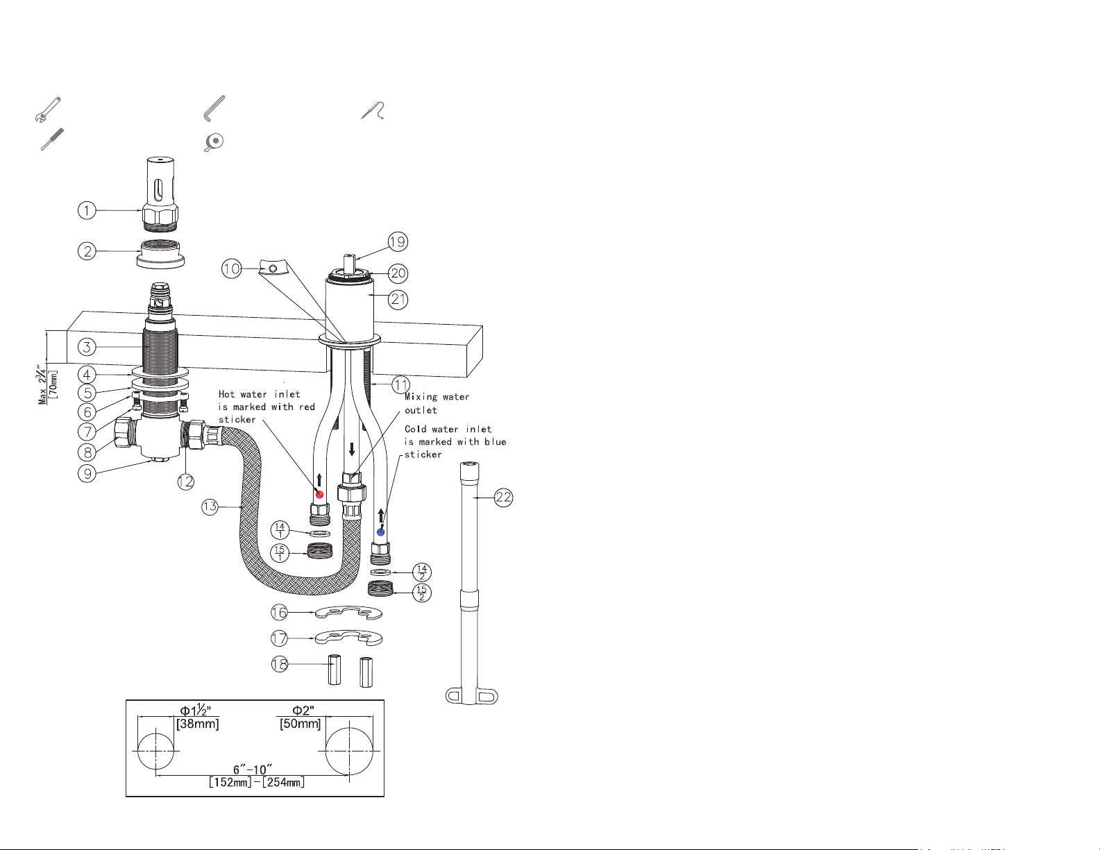
Tools Required for Installation
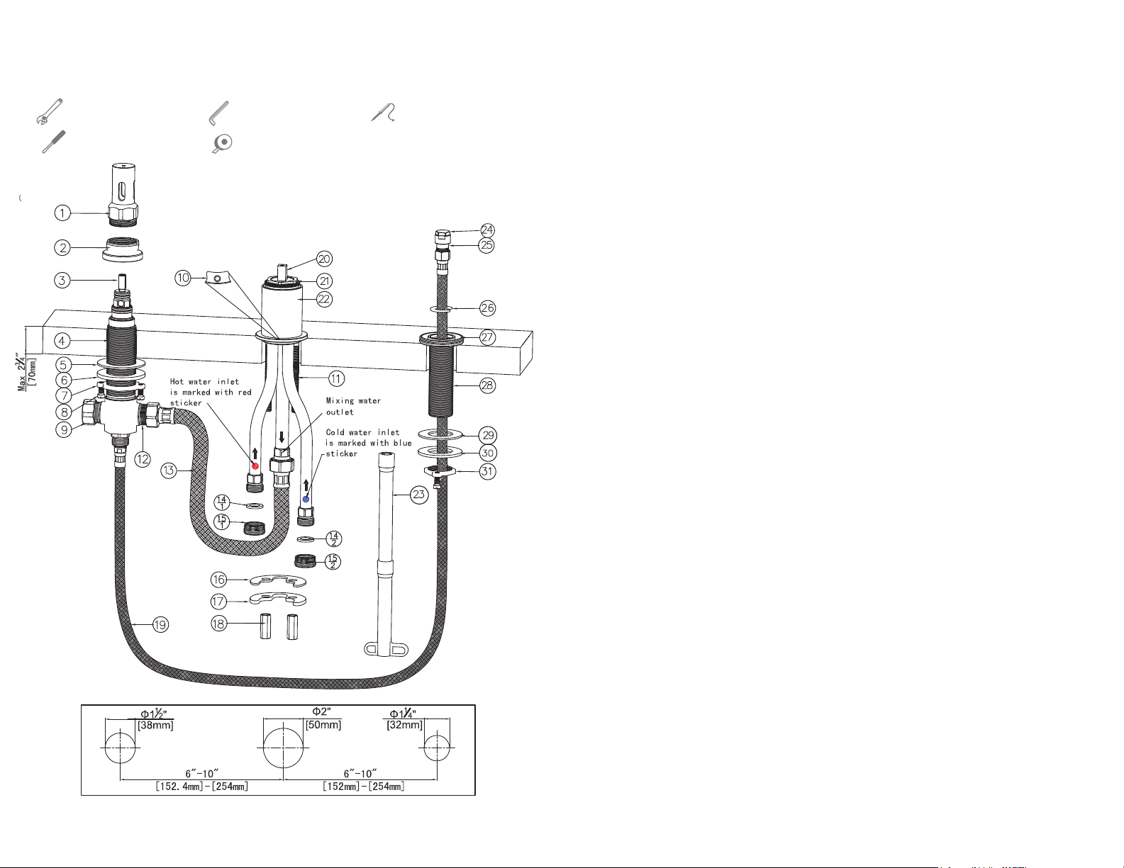
14. From underneath the deck, insert the capped
end (#24) of the braided hose (#19) through
hand shower assembly (#28).
LEAK TEST
1. Push test cap (#1) onto the top of spout
diverter assembly (#4) and thread onto top
nut (#2) until it stops.
2. Make sure braided hose (#19) is capped with
a test plug (#24).
3. Turn on cold and hot water supply lines and
inspect all connections for leaks.
4. On the finished deck, mark rough-in valve
installation location. Drill 1-1/2”(38mm) in
diameter for spout diverter assembly (#4),
drill 2” (50mm) in diameter for control unit
assembly (#22), and drill 1-1/4” (32mm) in
diameter for hand shower assembly (#28).
5. From underneath the deck, insert spout
diverter assembly (#4) through the hole with
mounting nut (#7), plate (#6) and gasket (#5)
on the spout diverter assembly (#4).
6. From above the deck, hand tighten top nut
(#2) onto diverter assembly (#4) until it stops.
8. From above the deck, insert control unit
assembly (#22) through the hole.
9. Slide mounting gasket (#16) and plate (#17)
over mounting rods (#11), and thread mount-
-ing nuts (#18) onto mounting rods (#11).
7. From underneath the deck, hand tighten
mounting nut (#7) until it stops. Then
tighten locking screws (#8) with a screw driver
to secure spout diverter assembly (#4).
10. Rotate control unit assembly (#22) until the
hole on the flange(10) points towards tub.
Then tighten mounting nuts (#18) with the
supplied socket wrench (#23).
1. Shut off cold and hot water supply.
2. Before installation, make sure the finished
deck thickness is no more than 2-3/4”(70mm).
12. From above the deck, insert hand shower
assembly (#28) through the hole.
15. Push plastic clip (#26) onto the braided hose
(#19) close to the capped end (#24). Slide down
plastic clip (#26) along the braided hose (#19)
and ensure that plastic clip (#26) sits inside the
groove of hand shower assembly’s top flange
(#27) to prevent the capped hose end (#24) from
dropping to below the finished deck.
11. Connect open port (#12) of spout diverter
assembly (#4) and outlet port (M) of control
unit assembly (#22) with the supplied 3/4”
braided hose (#13).
NOTE1: The capped port (#9) can be used.
NOTE2: Make sure braided hose (#13) is free
of kinks when it is connected.
16. Connect control unit assembly (#22) to water
supplies using proper fittings (flexible hose,
copper tubing, iron pipe or PEX -- check local
codes for proper connection). (C) is cold inlet
port marked with blue sticker and (H) is hot inlet
port marked with red sticker.
16.2. For 1/2” Copper Tube Soldering Connections,
NOTE: Prior to soldering, remove cartridge (#20)
by unscrewing retaining nut (#21). Avoid
soldering excessively at high temperature.
16.1. For 3/4” IPS Thread Connections, apply Teflon
tape onto threaded ends (#15) and connect
water supply flexible hose or tube to inlet
ports (#15).
remove 3/4” connectors (#15) and gaskets
(#14), then solder water supply tube to inlet
port (C) and (H).
3. The rough-in may be installed anywhere
on the deck. The distance between rough-
-in is recommended min 6”(152mm) and max
10”(254mm).
Adjustable Wrench Soldering Equipment
Screw Driver
Spout Diverter
Assembly
Control Unit
Assembly
Hand Shower
Assembly
Allen Wrench
Teflon Tape
(H)
(M)
(C)
13. From underneath the deck, slide mounting
gasket (#29) and plate (#30) onto hand
shower assembly (#28). Then tighten
mounting nut (#31) by hand until it stops,
and tighten locking screws with a screw
driver to secure.
3 4