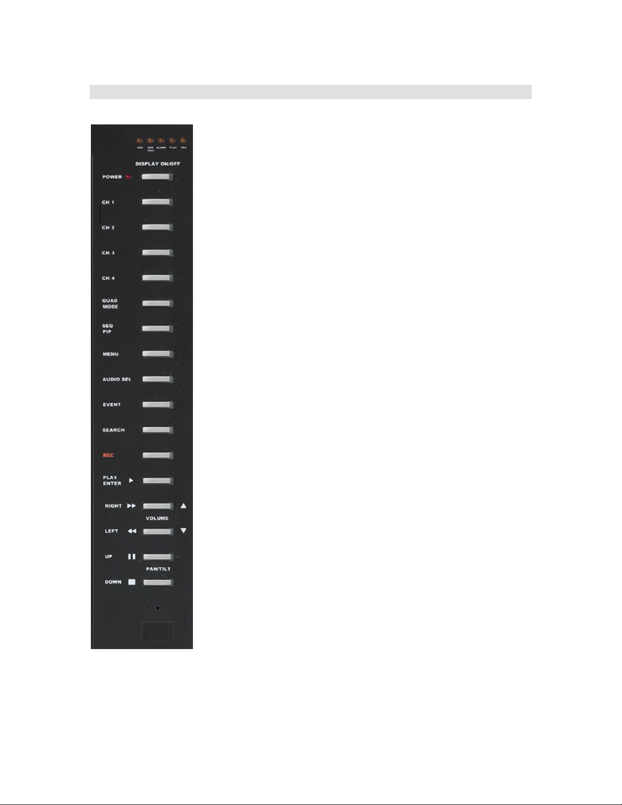
Sylvania SY17TD8144-A User manual

Model: SY17TD8144-A
17 Inch Flat Screen
TFT/4-Channel DVR
Copyright © 2006 LOREX Technologies Inc
English Version1.0
Instruction Manual

CAUTION: TO REDUCE THE RISK OF ELECTRIC SHOCK, DO NOT
REMOVE COVER (OR BACK). NO USER-SERVICEABLE PARTS INSIDE.
REFER FOR SERVICE TO QUALIFIED SERVICE PERSONNEL.
WARNING: To reduce the risk of fire or electric shock, do not expose this
appliance to rain or moisture
The lightning flash with arrowhead symbol, within an equatorial
triangle, is intended to alert the user to the presence of un-
insulated “dangerous voltage” within the product’s enclosure that
may be of sufficient magnitude to constitute a risk of electric
shock to persons.
The exclamation point within an equilateral triangle is intended to
alert the user to the presence of important operating and
maintenance (servicing) instructions in the literature
accompanying the product
This equipment has been tested and found to comply with the limits for a
Class B digital device, pursuant to part 15 of the FCC Rules. These limits
are designed to provide reasonable protection against harmful interference
in a residential installation. This equipment generated uses and can radiate
radio frequency energy and, if not installed and used in accordance with the
instructions, may cause harmful interference to radio communications.
However, there is no guarantee that interference will not occur in a
particular installation. If this equipment does cause harmful interference
radio or television reception, which can be determined by turning the
equipment off and on, the user is encouraged to try to correct the
interference by one or more of the following measures:
•Reorient or relocate the receiving antenna.
•Increase the separation between the equipment and receiver.
•Connect the equipment into an outlet on a circuit different from that to which
the receiver is connected.
Consult the dealer or an experienced radio/TV technician for help.
RISK OF ELECTRIC SHOCK DO NOT OPEN
CAUTION

TABLE OF CONTENTS
General Precautions............................................................................................................ 4
Introduction......................................................................................................................... 6
Features............................................................................................................................... 6
System Contents.................................................................................................................. 6
Installation........................................................................................................................... 7
Getting Started.................................................................................................................... 8
Front Panel Controls........................................................................................................... 9
Back Panel Connections ................................................................................................... 12
Pan / Tilt / Zoom Control and Connections...................................................................... 13
IR Remote Control Functions........................................................................................... 14
Entering the Sub Menu ..................................................................................................... 15
Menu Items ....................................................................................................................... 15
1. TIME / DATE SET -............................................................................................. 15
2. SEQUENCE SET -............................................................................................... 16
3. TITLE SET -......................................................................................................... 16
4. ALARM SET -...................................................................................................... 16
5. MOTION SET – ................................................................................................... 16
6. SYSTEM SET(I) - ................................................................................................ 17
7. SYSTEM SET(II) ................................................................................................. 17
9. ALARM REC SET ............................................................................................... 18
10. SCHEDULE REC SET..................................................................................... 18
Operation........................................................................................................................... 19
Video Search ................................................................................................................. 19
Video Playback ............................................................................................................. 19
Fast Forward and Fast Rewind.................................................................................... 19
Secondary (Slave) Hard Drive...................................................................................... 20
VGA Mode Controls......................................................................................................... 21
Expected Record Times.................................................................................................... 21
Specifications.................................................................................................................... 22

General Precautions
1. Read Instructions. All of the safety and operating instructions should be read and
understood before the product is used.
2. Retain Instructions. The safety and operating instructions should be retained for
future reference.
3. Heed Warnings. All warnings on the product and the instruction manual should be
followed.
4. Follow Instructions. All operating and instructions should be followed for optimal
performance
5. Cleaning. Disconnect the video product from the power supply before cleaning. Do
not use liquid cleaners or aerosol cleaners. Use a damp cloth for cleaning.
6. Attachments. Do not use attachments not recommended by the video product
manufacturer as they may cause hazards.
7. Water and Moisture. Do not use this product near water - for example, near a
bathtub, washbowl, kitchen sink, wet basement, or near a swimming pool.
8. Accessories. Use this product only with a stand, tripod, bracket or table
recommended by the manufacturer or sold with the product. Any mounting of the
product should follow the manufacturer’s instructions.
9. Ventilation. This product should never be placed near or over a Radiator or heat
register. This product should not be placed in a built-in installation, such as a book
case or rack, unless proper ventilation is provided or the Manufacturer’s instructions
have been adhered to.
10. Power Source. This product should be operated from the type of Power source
indicated by the marking label. If you are not sure of the type of power supply to your
location, consult your product dealer or your local Power Company
11. Power Cord Protection. Power supply cords should not be routed so that they are
likely to be walked on or pinched by items placed on or near them
12. Lightning. For added protection, unplug this product from its outlet during a lightning
storm. This will prevent damage to the video product due to lightning and power
surges
13. Overloading. To avoid the risk of fire and electric shock, do not plug this product into
an over-loaded power supply.
14. Object and Liquid Entry. Never push objects into the openings of this product as
they may touch dangerous voltage points that may result in fire or electric shock.
Never spill a liquid of any kind this product.

15. Servicing. Do not attempt to service this product yourself as opening or removing
covers may expose you to voltage or other hazards. Refer all servicing to qualified
service personnel
16. Damage Requiring Service. Disconnect this product from the power supply and
refer servicing to qualified service personnel under the following conditions:
a. When the power supply cord or plug is damaged
b. If objects have fallen into the product
c. If the product has been exposed to rain or liquids
d. If the product does not operate normally by following the instruction manual.
e. If the product has been dropped or the cabinet has been damaged
f. When the product displays a distinct change in performance - this indicates a
need for service
17. Replacement Parts. When replacement parts are required, be sure the technician
uses replacement parts specified by the manufacturer. Unauthorized substitutions
may result in fire, electric shock, or other hazards.
18. Safety Check. Upon completion of any service to this product ask the service
technician to perform safety checks to determine that the product is in proper
working condition.
19. Heat. The product should be situated away from heat such as radiators, hear
registers, stoves, or other products (including amplifiers) that produce heat.

Introduction
The SY17TD8144-A is a 17-inch, Flat Screen thin-film transistor (TFT) LCD color
monitor with integrated 4-channel Digital Video Recorder. Capable of resolutions up to
1280 x 1024, this advanced monitor produces crisp, clear pictures and brilliant colors.
The integrated DVR features M-JPEG compression and allows recording of up to 4 video
sources with an overall frame rate of 30fps. A removable Hard Drive bay supports up to
300 GB. Other advanced features include 2 Audio Input/Output channels, Built-in
speaker, and IR Remote Control.
Features
•17” Color LCD Monitor
•4 BNC Video Inputs
•4 Audio RCA inputs
•VGA input from PC
•30fps MJPEG compression
•Manual, Alarm, Motion, and Schedule recording
•On-Screen-Display Controls
•Resolution: 720 x 480 (NTSC), 1024 x 768 (VGA)
•450 TV Lines
•Low Power Consumption
•Built-In Interface for Wall or Arm Mounting VESA 75mm FPMPMI Compliant.
•Full digital image processing
•Tough and durable design for professional use
•Space saving attractive design
•Remote control or main panel operation
System Contents
•Main Unit – 17” monitor with integrated 4 channel DVR
•Table/Desk Mount base
•Rack Mount Ears
•Remote Control
•Installation Manual

Installation
1. The monitor comes with both a desk mount stand and rack mount ears. If using the
desk mount, secure the mount to the bottom of the monitor using the screws
provided (Fig 1.0). If rack mounting, secure the rack mount ears to each side of the
monitor using the included screws (Fig 1.1).
2. Make the appropriate video connections.
I. BNC Inputs – Connect the desired cameras to the BNC video inputs.
II. VGA Input – If wishing to use the monitor to view the video signal from a PC,
connect the cable from a PC video card to the input labeled VGA In.
3. If using audio, connect the RCA audio cable to the desired channel. Each channel
also provides an RCA Audio Out connector.
4. Plug the power cord into a nearby power outlet. Note that there is also a main power
toggle switch on the side of the monitor.
Figure 1.0 Figure 1.1

*** MASTER HDD ***
HDD AUTO DETECT…….OK
HDD R/W CHECK………..OK
HDD SPACE ( xxxGB)…….OK
MODEL# XXXXXXXXXX
Getting Started
1. Ensure that all connections have been made as shown in the previous section. Press
the Power Button on the front of the unit.
2. Upon Powering Up, a message will appear “Please Check HDD Key Lock before
Turn ON”. This message is reminding you to ensure that the cabinet of the DVR is
locked before proceeding.
3. The check of the HDD key lock will be followed by
an overall diagnostic check of the HDD. The screen
will appear as shown to the right:
Note: If you get a “FAIL” message in HDD Auto Detect, the HDD is not installed
correctly. Confirm that the HDD is set to master and that the tray is locked.

Front Panel Controls
1. LED Indicators – HDD, HDD Full, ALARM, REC, PLAY
2. POWER ON/OFF button
3. CHANNEL 1 select button
4. CHANNEL 2 select button
5. CHANNEL 3 select button
6. CHANNEL 4 select button
7. QUAD view select / MODE select button
8. SEQ view / PIP mode
9. MENU enter button
10. Audio channel select
11. Event History Log
12. SEARCH function button
13. RECORD start button
14. PLAY button / ENTER function button
15. RIGHT directional button / FF button / Volume UP button
16. LEFT directional button / REW button / Volume DOWN button
17. UP directional button / PAUSE button / PAN and TILT button
18. DOWN directional button / STOP button

1) LED Indicators
I. HDD – Illuminates when the HDD is being accessed.
II. HDD FULL - Blinks when the remaining space of HDD is less than 1GB.
III. ALARM – This LED will be on when the ALARM or MOTION function is set.
When an ALARM or MOTION event is detected, the LED will blink.
IV. PLAY – The LED will be on when play the data has been stored into the HDD.
V. REC – The LED will be on when store the data into the HDD.
2) POWER – Press this button to power on/off the display.
3) CH 1 – Press this button once to FREEZE the display of channel 1. The letter ‘F’ will
appear on screen to indicate this.
Press and hold this button to view Channel 1 in full screen mode.
4) CH 2 - Press this button once to FREEZE the display of channel 2. The letter ‘F’ will
appear on screen to indicate this.
Press and hold this button to view Channel 2 in full screen mode.
5) CH 3 - Press this button once to FREEZE the display of channel 3. The letter ‘F’ will
appear on screen to indicate this.
Press and hold this button to view Channel 3 in full screen mode.
6) CH 4 - Press this button once to FREEZE the display of channel 4. The letter ‘F’ will
appear on screen to indicate this.
Press and hold this button to view Channel 4 in full screen mode.
7) QUAD / MODE - Press this button once to display the cameras in a quad screen.
Press and hold the button for 2 seconds to switch between NTSC and VGA modes.
8) SEQ / PIP –
Press once to begin a camera sequencing display. Press and hold to activate
Picture in Picture mode.
This button triggers the Picture-In-Picture displays. PIP allows you to view two
locations simultaneously, one being the main channel, the other being viewed as a
picture in picture. Dual PIP can also be selected, which displays two picture in
picture boxes on the main screen.
If you do a short press of the button on the PIP mode, it turns to pip screen, long
press turns to main screen.
NOTE : You cannot turn both sub channels to OFF while in PIP mode.
9) MENU – Press and hold this button for 2 seconds to enter the setup menu.
10)EVENT – Press this button to bring up an Event History or Alarms and other error
events. This log records the 1000 most recent events.
A time/date stamp along with one of the letters below will be shown for each event.
P : Shows the time when the power was on.
A : Shows the time when the ALARM was detected.
M : Shows the time when the MOTION was detected.
L : Shows when the LOSS from Camera was detected.

11)SEARCH – Press this button to enter the search menu. See ‘Searching Video’ in the
‘Operation’ section for instructions on navigating the search menu.
12)REC - Press this button once to begin manual recording.
13)PLAY / ENTER – Press this button once to begin playing back the most recent
recording. When in the Menu setup, use this button to Enter a selection.
14)FF / RIGHT / VOLUME ▲
During playback, use this button to Fast Forward the video.
When in the Menu setup or Search function, use this button to scroll to the right.
In the normal mode, use this button to increase the speaker volume.
15)REW / LEFT / VOLUME ▼
During playback, use this button to Rewind the video.
When in the Menu setup or Search function, use this button to scroll to the left.
In the normal mode, use this button to decrease the speaker volume.
16)PAUSE / UP / PAN/TILT
During playback, use this button to Pause the video.
When in the Menu setup or Search function, use this button to scroll Up.
In the normal mode, use this button to enter the Pan/Tilt/Zoom function.
17)STOP / DOWN
During playback, use this button to Stop the video.
When in the Menu setup or Search function, use this button to scroll Down.

Back Panel Connections
1. BNC Camera Inputs - Channel 1-4 camera inputs
2. RCA Audio inputs - Channel 1-4 Audio inputs
3. Monitor A/V Out - Audio/Video out for an additional monitor.
4. Slave A/V Out - Audio/Video for a VCR or other video equipment.
5. Alarm Input and Trigger Out – External Alarm inputs for Channels 1 – 4.
Connect external alarm sensors between the alarm input and ground.
6. RS-485 Terminals – Connect the PTZ control wires to these terminals.
7. VGA IN – Connect the VGA signal from a PC to this input.
8. RS-232C Terminal - For connection of the RS-232C terminal of the unit to a
computer, please use a special RS-232C cable.
9. VGA IN IDE-SUB - This connector will be used for external HDD.
1
2
3
4
5
6
7
8
9

Pan / Tilt / Zoom Control and Connections
The DVR supports the control of a single Pan/Tilt/Zoom camera on Channel 1.
Currently only PTZ camera’s using the ‘Pelco D’ protocol may be used.
1) Connect a compatible PTZ camera to Channel 1
2) Connect the RS-485 control wires to the RS-485 terminals on the back of the
monitor.
3) Go to the SYSTEM submenu and set the PAN/TILT(CH1) option to “Y”;
4) Enter Pan/Tilt Zoom mode by holding the PAN/TILT key on the monitor for 3
seconds, or press the Pan/Tilt button on the remote control
5) You will see a contracted screen with a blue border. Use the Arrow keys to move
sideways, and ENTER to select whether to MOVE, ZOOM, or FOCUS the
camera.
6) If you have selected MOVE, you can use all four-arrow keys to Pan and Tilt in all
directions. If you selected ZOOM or FOCUS, use the arrow keys to Zoom /
Focus IN and OUT.
7) Select and press ENTER on the EXIT option to escape the Pan/Tilt mode.
Note: the system automatically exits Pan/Tilt mode after 20 seconds of inactivity.
Refer to the diagram below for an illustration of Pan/Tilt Zoom mode.

IR Remote Control Functions

Entering the Sub Menu
Pressing and holding the MENU button for 2 seconds access’s the Main Menu.
Use the UP/DOWN buttons to scroll between menu items. The ENTER button is used to
select a section and enter its sub-menu. To change a toggle option, use the ENTER key
to enable/disable. To change a data option, use the ENTER key and directional buttons.
Exit the Main Menu, scroll down to the Exit option and press Menu.
To exit from a sub-menu back to the main menu scroll to Return and press ENTER. To
exit the menu entirely, scroll to Exit and press ENTER.
Please note that the menu will timeout after 20 seconds of no key presses.
Menu Items
1. TIME / DATE SET -
The following options can be changed in this section.
DISP MON : [Y] Selecting [Y] enables on screen display of the date & time.
Selecting [N] hides this information.
DISP REC : [Y] Selecting [Y] will cause the date & time info to be recorded into
tape. Selecting [N] prevents will prevent the on-screen display
from being recorded.
TIME : 12:00:00 Change the time (24 hour clock)
DATE : 1/1/2004 Change the date.
DATE
FORMAT : MM/DD/YYYY There are three formats to display the date:
MM-DD-YYYY : for U.S.A.
YYYY-MM-DD : for Asian countries.
DD-MM-YYYY : for European countries.

2. SEQUENCE SET -
QUAD :
03 sec
CH1 :
03 sec
CH2 :
03 sec
CH3 :
03 sec
CH4 :
03 sec
Select the amount of time the unit will stay on each screen
when the unit is in Sequence mode.
Valid dwell times are 00 – 59 seconds. Setting a channel to 00
will remove that channel from the sequence.
3. TITLE SET -
DISPLAY : [Y]
CH1 :
[CH1]
CH2 :
[CH2]
CH3 :
[CH3]
CH4 :
[CH4]
Select whether the Channel names will appear in the On
Screen Display.
The title for each channel is entered in this section as well.
Each title may be up to 8 characters long.
4. ALARM SET -
The DVR can be triggered externally via 4 Alarm input terminals on the back of the
unit. When triggered, the unit will show ‘AL’ on the display as well as sound the
buzzer if enabled. This alarm may also be used to trigger recording if enabled in
menu #9 -ALARM REC SET.
ALARM : [OFF]
CH1 :
03 SEC [N/O]
CH2 :
03 SEC [N/O]
CH3 :
03 SEC [N/O]
CH4 :
03 SEC [N/O]
The ALARM enable option may be changed from [OFF] to
[OSD] (On Screen Display) or [OSD + Buzzer].
The alarm duration may be changed for each channel from 01
to 59 seconds.
Also, the input trigger for each channel may be changed from
[N/O] Normally Open, [N/C] Normally Closed or [OFF].
5. MOTION SET –
The DVR has built-in video motion detection. If enabled, a change in the camera
image will cause the unit to register an alarm and show the letters ‘MD’ on the
display. The buzzer will also sound if enabled.
Motion detection can also be used to trigger recording. In order for this to function,
alarm recording must be enabled in menu #9 – ALARM REC SET.
MOTION :
[OFF]
CHANNEL : [01]
SENSITIVITY : [03]
AREA :
[00]
The MOTION enable option may be changed from [OFF] to
[OSD] (On Screen Display) or [OSD + Buzzer].
Select the CHANNEL and then adjust the sensitivity and active
area for that camera.
SENSITIVITY may be adjusted from [00-05] where 5 is the most
sensitive.
The AREA may be adjusted to one of 6 detection patterns as
shown below. Select [00] for full screen detection.

Motion Detect Zones:
6. SYSTEM SET(I) -
KEY BUZZER : [Y] When enabled, a tone will sound for each key press on the unit.
LOSS BUZZER : [Y] When enabled, a tone will sound when video signal is lost.
QUAD LINE : [Y] This option activates/deactivates the border-line separation in
Quad Mode.
BLANK COLOR : [BLUE] This allows you to toggle the blank screen color from Blue, Gray or
Black
SLAVE OUT : [QUAD] This selects whether the Slave output will be QUAD always, or
ACTUAL, which outputs what is shown on the display.
TITLE/TIME : [TL/TR] This allows you to change the OSD position for the camera Titles
and Time. The default setting is Top Left for Tile and Top Right for
Time.
PAN/TILT : PAN/TILT Enables/Disables Pan Tilt support on Channel 1.
ALARM OUT : N/O This selects whether the Alarm Output will be a Normally Open or
Normally Closed activation.
DEFAULT SET : [N] Selecting Yes for this option sets all program settings including
Time/Date back to their factory defaults.
7. SYSTEM SET(II)
HDD INFO DISP : [BYTE] This option selects whether the OSD Hard Drive information will
be shown as [BYTE} for number of remaining bytes or [PERCENT]
for the percent of the drive remaining.
RS-232 BAUD
RATE : [OFF] This sets the RS-232 baud rate if connecting to a PC for control of
the DVR. Selectable baud rates are [2400], [4800], [9600] and
[19200]
PASSWORD :
[N] This option determines whether a password will be required to
enter the setup menu.
PASSWORD
SET : [0000] If password protection is desired, enter the password in this
section. Press Enter when complete.
8. HDD/REC SET
REC QUALITY : [BEST] Select the quality setting to be used for recording – [LOW],
[NORMAL], [HIGH], or [BEST]
00 02
03 04
01 05

REC SPEED : [60] IPS Select the images per second (IPS) that the unit will record. Note
that this is an overall value and is split between the active cameras.
Example – 60 IPS / 4 (cameras) = 15 IPS per camera
REC SELECT : CH1 – CH4 Each channel may be enabled/disabled from recording using this
option.
HDD CLEAR
ALL : [N] The HDD may be cleared of all data in this section. Press ENTER to
change to [MASTER], and then press the RIGHT button to select
Yes to erase.
HDD
OVERWRITE : [N] This option selects whether the unit will begin overwriting old
information when the HDD fills, or stop recording when the HDD is
full.
HDD SLAVE : [N] Select [Y] is connecting an external slave drive.
9. ALARM REC SET
ALARM REC : [N] Select whether the DVR will begin recording upon an alarm event.
Alarm events include the external activation and or motion detection.
REC QUALITY : [BEST Select the quality setting to be used for alarm recording – [LOW],
[NORMAL], [HIGH], or [BEST]
REC SPEED : [60] IPS Select the images per second (IPS) that the unit will record when
activated. Note that this is an overall value and is split between the
active cameras. Example – 60 IPS / 4 (cameras) = 15 IPS per
camera
REC
DURATION : [N] Select the record duration to be used when an alarm is detected.
Valid entries include – 1/5/15/30 MIN, 1Hr, and Continuous.
10. SCHEDULE REC SET
SCHEDULE REC :
[DAILY] - Recording will be carried out according to time in a daily. Date will be
disregarded.
[OFF] - No schedule.
[ONCE] - Recording will be carried out according to the schedule.
[SCHEDULE REC SET ]
SCHEDULE REC : [ OFF ]
N0 : _ _ / _ _ _ _ : _ _ -> _ _ / _ _ _ _ : _ _
N1 : _ _ / _ _ _ _ : _ _ -> _ _ / _ _ _ _ : _ _
N2 : _ _ / _ _ _ _ : _ _ -> _ _ / _ _ _ _ : _ _
N3 : _ _ / _ _ _ _ : _ _ -> _ _ / _ _ _ _ : _ _
N4 : _ _ / _ _ _ _ : _ _ -> _ _ / _ _ _ _ : _ _
N5 : _ _ / _ _ _ _ : _ _ -> _ _ / _ _ _ _ : _ _
N6 : _ _ / _ _ _ _ : _ _ -> _ _ / _ _ _ _ : _ _
N7 : _ _ / _ _ _ _ : _ _ -> _ _ / _ _ _ _ : _ _
RETURN : { J ]
EXIT : { J ]
11. TFT SET –
Adjust the monitor’s Contrast, Brightness. You will see this menu on your camera
setting rather than on a blue background, enabling you to see the
changes being made to the picture.

NOTE : Displays whether HDD in use is for MASTER or SLAVE.
When MASTER HDD is in use, it displays “M”, “S” for SLAVE HDD.
NOTE : When the Power is On, a message appears as follows, “Please Check HDD
KeyLock Before Turn On”
Operation
Video Search
Press the SEARCH button to access the ‘PLAYBACK SEARCH SET’ menu.
[PLAYBACK SEARCH SET]
1. LAST RECORD: Plays the most recent recording.
2. FULL LIST: Shows a listing of all recorded video on the HDD, sorted
by time.
3. ALARM LIST: Shows a listing of all recorded video triggered by an
Alarm.
4. TIME SEARCH: Finds video recorded on a specific date and time that
is entered.
5. EXIT: Exits Search mode.
A listing of up to 1000 recordings can be stored in both the ALARM LIST and the FULL
LIST. You can scroll through Recordings using the UP and DOWN keys, and navigate
between Pages of Recordings using the LEFT and RIGHT keys.
To view a selected piece of video on the list, press the PLAY / Enter button on the
highlighted recording. The selected video will begin playing. You can stop the video at
any time by pressing the STOP button.
Video Playback
Pressing the PLAY button will bring up the Search option that was last used. Whichever
Search option you last accessed will dictate which Playback menu appears upon
pressing PLAY. For example, if the last Search option used was a Time Search, then
pressing PLAY will bring up the Playback Time Search. If the last Search option utilized
was a Last Record, then pressing play will simply play the most recent recording.
Fast Forward and Fast Rewind
You can increase the speeds of Fast Forward and Rewind on the DVR.
While in PLAY mode, pressing the FF / REW button once initiates FF / REW data speed
of 2X.
Pressing the FF / REW button a second time increases the FF / REW speed to 4X.
Pressing the FF / REW button a third time increases the FF / REW speed to 8X.
The maximum FF / REW speed is 128X.
To terminate FF / REW, press the PLAY button, which will Pause the screen. You can
then retry FF / REW, or proceed to press PLAY again for standard Playback.

Secondary (Slave) Hard Drive
The Master HDD is the removable drive accessible on the side of the monitor.
On the back of the monitor there is an IDE-SUB input for connecting another HDD to
serve as a backup to the Master HDD, providing extra storage space.
To connect a Slave HDD, you will need an External IDE drive with a built-in power
supply. LOREX Techologies Inc. will be offering this in the future as an accessory to
the product. Please visit http://www.lorexcctv.com for updates as to when this
will be available.
Note that once you have connected a Slave HDD, it needs to be activated. This is done
in the ‘HDD / REC SET’ menu.
When recording to the Master HDD becomes Full, the Slave HDD commences receiving
the earliest recorded data from the Master HDD. Therefore, data is not lost, as it gets
transferred to the Slave HDD. The most recent recordings are found on the Master HDD.
Table of contents
Other Sylvania DVR manuals