Sylvania 4SYY600STS User manual

1
SYLVANIA is a registered trademark of OSRAM SYLVANIA Inc., used under license.
STAINLESS STEEL RANGE HOOD
ITM./ART/ 555495
MODEL NO. 4SYY600STS (QCKB2006C)
IMPORTANT:
PLEASE NOTE WHEN YOU OPEN THE CARTON CAREFULLY CHECK
THE UNIT AND MAKE SURE THERE IS NO DAMAGE. IF YOU HAVE ANY
PROBLEMS WITH ASSEMBLING THE UNIT, WITH HOW THE VARIOUS
FUNCTIONS WORK OR WITH DAMAGE OR MISSING PARTS PLEASE
CALL 1-800-459-4409 (9:00AM - 5:00PM EST) IMMEDIATELY FOR
SERVICE.
READ & SAVE THESE INSTRUCTIONS
FOR RESIDENTIAL USE ONLY
PLEASE READ THIS GUIDE BEFORE INSTALLING AND USING YOUR
RANGE HOOD.
STORE THIS GUIDE IN A SAFE PLACE FOR CLEANING AND
MAINTENANCE REFERENCE.
INSTALLATION MUST COMPLY WITH ALL LOCAL CODES.
• Requirement:120VAC,60Hz,15or20Abranchcircuit.
• Readallinstructionsbeforeproceeding.
• Approvedforresidentialuseonly.
• Turnoffpowercircuitbreakerbeforewiringthisappliance.
Themanufactureranddistributorsdeclineallresponsibilityintheeventoffailure
toobservetheinstructionsgivenhereforinstallation,maintenanceandsuitable
useoftheproduct.Themanufactureranddistributorsfurtherdeclineallrespon-
sibilityforinjuryduetonegligenceandthewarrantyoftheunitautomatically
expiresduetoimpropermaintenance.
IMPORTANT SAFETY INSTRUCTIONS
READ ALL INSTRUCTIONS BEFORE INSTALLING AND OPERATING THIS
APPLIANCE.
CAUTION
• DONOTINSTALLIFTHEAPPLIANCEISDAMAGED.
• ALL ELECTRICAL WIRING MUST BE PROPERLY INSTALLED, INSU-
LATED AND GROUNDED. OLD DUCT WORK SHOULD BE CLEANED OR
REPLACED IF NECESSARY TO AVOID THE POSSIBILITY OF A GREASE
FIRE. CHECK ALL JOINTS ON DUCT WORK TO ENSURE PROPER CON-
NECTION. ALL JOINTS SHOULD BE PROPERLY TAPED.
• PERSONALINJURYHAZARD.BECAUSEOFTHEWEIGHTANDSIZEOF
THE RANGE HOOD, TWO OR MORE PEOPLE ARE NEEDED TO MOVE
AND SAFELY INSTALL THE RANGE HOOD. FAILURE TO PROPERLY LIFT
RANGE HOOD COULD RESULT IN DAMAGE TO THE PRODUCT OR PER-
SONAL INJURY.
• SEVEREINJURY-RANGEHOODMAYHAVEVERYSHARPEDGES.WEAR
PROTECTIVE GLOVES TO REMOVE ANY PARTS FOR INSTALLING, CLEAN-
ING OR SERVICING.
• ALWAYSLEAVESAFETYGRILLSANDFILTERSINPLACE.WITHOUTTHESE
COMPONENTS, OPERATING BLOWERS COULD CATCH ON TO HAIR, FIN-
GERS AND LOOSE CLOTHING.
• NEVERDISPOSEOFCIGARETTEASHES,IGNITABLESUBSTANCESORANY
FOREIGN OBJECTS IN BLOWERS.
WARNING: THIS SAFETY ALERT SYMBOL ALERTS YOU TO POTENTIAL
HAZARDSTHATCANKILLORHURTYOUANDOTHERS.ALLSAFETY
MESSAGES WILL FOLLOW THE SAFETY ALERT SYMBOL AND THE WORD
“WARNING”.
WARNING: TO REDUCE THE RISK OF FIRE, ELECTRIC SHOCK, OR
INJURY TO PERSONS, OBSERVE THE FOLLOWING CAREFULLY:
1) USE THIS UNIT ONLY IN THE MANNER INTENDED BY THE MANUFAC-
TURER. IF YOU HAVE ANY QUESTIONS REGARDING THIS RANGE HOOD,
CONTACT THE MANUFACTURER.
2) BEFORE INSTALLING, SERVICING OR CLEANING THE UNIT, SWITCH
POWER OFF AT THE MAIN JUNCTION BOX AND LOCK THE PANEL DOOR
TO PREVENT POWER FROM BEING SWITCHED ON ACCIDENTALLY. IF
THE JUNCTION BOX DOOR CANNOT BE LOCKED, SECURELY FASTEN A
PROMINENT WARNING SIGN TO THE PANEL DOOR.
3) INSTALLATION OF ELECTRICAL WIRING MUST BE DONE BY A QUALI-
FIED ELECTRICIAN IN ACCORDANCE WITH ALL APPLICABLE LOCAL
AND NATIONAL CODES AND STANDARDS, INCLUDING FIRE CODES. THE
INSTALLER AGREES TO ABIDE BY THESE LOCAL AND NATIONAL REGULA-
TIONS AT THEIR OWN EXPENSE.
4) SUFFICIENT AIR IS NEEDED FOR PROPER COMBUSTION AND EXHAUST-
ING OF GASES THROUGH THE FLUE (DUCT WORK). FOLLOW THE RANGE
EQUIPMENT MANUFACTURER’S GUIDELINES AND SAFETY STANDARDS
SUCH AS THOSE PUBLISHED BY THE NATIONAL FIRE PROTECTION
ASSOCIATION (NFPA) AND THE AMERICAN SOCIETY FOR HEATING,
REFRIGERATION AND AIR CONDITIONING ENGINEERS (ASHRAE), AND
THE LOCAL CODE AUTHORITIES.
5) WHEN CUTTING OR DRILLING INTO A WALL OR CEILING, DO NOT DAM-
AGE ELECTRICAL WIRING AND HIDDEN UTILITIES.
6) DUCTED FANS MUST ALWAYS BE VENTED TO THE OUTDOORS. DO NOT
VENT EXHAUST AIR INTO SPACES WITHIN WALLS, CEILINGS, ATTICS,
CRAWL SPACES, OR GARAGES.
7) TO REDUCE THE RISK OF FIRE OR ELECTRIC SHOCK, DO NOT USE THIS
HOOD WITH ANY SPEED CONTROL DEVICE.
8) WARNING: TO REDUCE THE RISK OF FIRE, USE ONLY METAL DUCT
WORK.
9) WARNING: FOR GENERAL VENTILATION USE ONLY. DO NOT USE THE
RANGEHOODFANSTOEXHAUSTHAZARDOUSOREXPLOSIVEVAPORS.
TO REDUCE THE RISK OF INJURY IN THE EVENT OF A RANGE TOP GREASE
FIRE, OBSERVE THE FOLLOWING:
1) WARNING: SMOTHER FLAMES WITH A LID, COOKIE SHEET, OR
METAL TRAY, THEN TURN OFF THE BURNER. BE CAREFUL TO PREVENT
BURNS. IF THE FLAMES DO NOT GO OUT IMMEDIATELY, EVACUATE AND
CALL THE FIRE DEPARTMENT.
2) WARNING: NEVER PICK UP A FLAMING PAN, YOU MAY BE
BURNED.
3) WARNING: DO NOT USE WATER, INCLUDING WET DISHCLOTHS OR
TOWELS. A VIOLENT STEAM EXPLOSION MAY RESULT.
4) USE A FIRE EXTINGUISHER ONLY IF:
A) YOU KNOW YOU HAVE A CLASS ABC EXTINGUISHER AND YOU
ALREADY KNOW HOW TO OPERATE IT.
B) THE FIRE IS SMALL AND CONTAINED IN THE AREA WHERE IT
STARTED.
C) THE FIRE DEPARTMENT IS BEING CALLED.
D) YOU CAN FIGHT THE FIRE WITH YOUR BACK TO AN EXIT.
5) NEVER LEAVE RANGE UNATTENDED WHEN IN USE.

2
6) BOIL OVERS CAUSE SMOKE AND GREASY SPILL OVERS THAT MAY IG-
NITE.
7) HEAT OILS SLOWLY ON LOW OR MEDIUM SETTING. OVERHEATING MAY
CAUSE OIL TO REACH ITS FLASH POINT AND IGNITE. USED OIL WILL
IGNITE AT LOWER TEMPERATURES THAN FRESH OIL.
8) ALWAYS TURN HOOD ON WHEN COOKING AT HIGH HEAT OR WHEN
COOKING/FLAMBÉINGFOODS(I.E.CRÊPESSUZETTE,CHERRIESJUBILEE,
BEEF FLAMBÉ).
9) CONSTANTLY MONITOR DEEP FRYERS DURING USE AS OVERHEATED OIL
MAY IGNITE.
10) CLEAN VENTILATION FANS FREQUENTLY. GREASE SHOULD NOT BE AL-
LOWED TO ACCUMULATE ON FAN OR FILTERS.
11)ALWAYSUSECOOKWAREAPPROPRIATEFORTHESIZEOFTHESURFACE
ELEMENT.
TOOLS REQUIRED (NOT INCLUDED)
Marker or pencil
Needle nose pliers
Hammer
Measuring tape
Level
Powered screwdriver
or drill
Utility knife
Flat blade and Phillips
screwdrivers
PVC electrical
tape
Adjustable wrench
PARTS
Rangehood(with2lters)................................................................................................ 1
Damper(locatedinsidethehood)................................................................................... 1
Screw(ø5/32”x5/16”) ..................................................................................................... 2
Screw(ø3/18”x1-1/8”) .................................................................................................... 4
Wirenut(twist-onwireconnector).................................................................................. 3
Installation guide .................................................................................................................................1
Screw x 2
(ø 5/32" x 5/16")
Screw x 4
(ø 3/18" x 1-1/8")
Damper x 1
Wire nut x 3
(twist-on wire
connector)
Installation guide
Range hood x 1
9"
29.8"
3.2"
12"
18"
GETTING STARTED
REMOVING EXISTING RANGE HOOD
Ifanexistingrangehoodisinstalled,itmustbecarefullyremoved.Thisshouldbe
donewithahelper.
Althoughtheseinstructionswon’tapplytoeverykindofrangehood,theywillprovide
anoverviewoftheprocess.
1. WARNING: DISCONNECT POWER SOURCE.
Turnthefanandlight(ifequipped)oftheexistingrangehoodon,andhavea
helperturncircuitsoffandthenbackonuntilthefanandlightbothshutoff.If
unabletolocatethecircuit,turningofftheservicedisconnectormainshouldshut
powerofftotheentirehouse.
2. Covertherangetopwithcardboardoraprotectiveblankettoensureitdoesnot
getdamagedduringtheremovalandinstallationofthenewrangehood.
3. Inspectthecabinetorotherstorageareaabovetherangehood.Thiscanprovidea
greatdealofinformationastohowthehoodissecured,poweredandducted.
4. Removeallcovers,lters,lightbulbs,etc.Manytimes,rangehoodsareheldbyone
ormorefastenersthatmaybehiddenbehindtheseobjects.
5.Identifywiringconnections.Oneofthecoversremovedaboveshouldprovideac-
cesstothewiringcompartment.Thisiswherethehousepowerisbroughtintothe
rangehoodandconnectedtoit.
6. Disconnectwiring.Generally,white,blackandpossiblyagreenorbarewiresfrom
thehoodareconnectedtolikecolorsofwiresfromacableorconduitwithwire
nutsorotherconnectorsdesignedforthepurpose.Unscrewwirenutsorother
devices,cutoffanywiresconnectedwithcrimpedconnectorsasclosetothecon-
nectortoleaveasmuchwireaspossible.
7. Ifthebottomoftherangehoodwaspreviouslycaulked,takeasharpknifeand
scoreitallthewayaroundsoitwillbeeasiertoremove.
8. Withahelperprovidingsupporttothehood,removeallbuttwofasteners.Leave
twofastenersatoppositeendsofthehoodinplace.Merelyloosenthesetwo
enoughtopeerintothevoidbetweenthesupportsurfaceandthehoodtoseehow
theunitispowered.
9. Haveahelperholdthehoodwhilethenaltwoscrewsareremoved.
10.Thehoodwillbeconnectedonlybythepowersourcecableorconduit(ifunableto
disconnectinpreviousstepsabove)orductwork.Disconnectthewiringfromthe
powersource.Checkforthepresenceofanyscrewsusedtoconnectthehoodto
ductwork,andremovethem.Thehoodshouldnowbeabletobemovedfreely.

3
PREPARATION
VENTING
Thisrangehoodcanbetoporbackvented.Checktoseewhichventingmethodyou
have.Ifthisisanewinstallation,choosewhichventingmethodsuitsyourneeds.
NOTE:Beforemakinganycutsorholesforinstallation,carefullymeasureandmark
allmeasurements.Doublecheckallmeasurementmarkingsbeforecutting.
IMPORTANT:
- Ventsystemmustterminateoutdoors(throughrooforsidewall).
-
Donotterminatetheventsysteminanatticoranyotherenclosedarea.
- Useonlymetal/exiblealuminumvents.
- Neveruseplasticvents.
- Alwayskeepductscleantoensureproperairow.
- NEVERexhaustairorterminateductworkbetweenwalls,crawlspaces,ceilings,
attics or garages.
- Usecaulkingtosealexteriorwallorroofopeningaroundthecap.
- Donotuse4”laundrytypewallcaps.
- It is recommended that the range hood be vented vertically through the roof
through6inroundmetal/aluminumductwork.Thesize of the vent should be
uniform.
- Usenomorethanthree90 degreeelbows.Donotinstalltwoelbowstogether.
-
Makesurethereisaminimumof18
”
ofstraightductbetween
theelbowsifmore
thanone elbow is used. The length of the vent system and number of elbows
shouldbekepttoaminimumforeffectiveperformance.
- Theventsystemmusthaveadamper.Ifrooforwallcaphasadamper,donotuse
dampersuppliedwiththerangehood.
- Useducttapetosealalljointsintheventsystem.
- Fastenallconnectionswithsheetmetalscrewsandtapealljointswithducttape.
VERTICAL ROOF VENTING
Ducting through the roof
HORIZONTAL WALL VENTING
Ducting through the wall
Wall cap
Damper
Wall
Pipe
Roof
Roof
Pipe
Damper
Cabinet
Range hood
Roof cap
Cabinet
Range hood
CALCULATE THE DUCT RUN LENGTH:
Ifductedwiththerequiredminimumof6”roundductwork,theductrunshouldnot
exceed35ft.Calculatethe length oftheduct work by addingtheequivalent feet as
belowforeachpieceofductinthesystem.
Ifyoumustelbowrightaway,doitasfarawayfromthehoodsexhaustopeningas
possible.
45
o
Elbow 36"
90
o
Elbow 60"
90
o
Flat elbow 144"
Wall cap 0"
2.74 m (9 ft) Straight duct 108"
2-90
o
Elbow 120"
Wall cap 0"
Total system 228"
• Beforemakingcuts,makesurethereisproperclearancewithintheceilingorwall
forexhaustvent.
• Checkyourceilingheightandthehoodheightbeforeyouinstallyourrangehood.
Thehoodinstallationheightabovethecooktopcanvary slightly.A lowerhood
ensuresmoreeffectivecaptureofcookingodors,greaseandsmoke.However,the
hoodshouldbeinstalledaminimumof18”andamaximum30”abovetherange
top.
• Screwsareprovidedtosecuretherangehoodtomosttypesofcabinets.Youshould
consultaqualiedinstallertoverifythatthesuppliedscrewsaresuitableforyour
cabinets.
• Themanufacturerassumesnoresponsibilityforinjuryand/ordamagecausedby
improperinstallation.
• Putaprotectivecoveringoveryourcountertop,cooktopandrangetoprotectfrom
damageanddirt.Removeanyhazardousobjectsaroundtheareawheninstalling.
CABINET PREPARATION
MEASUREMENTS
Thisproductisdesignedforundercabinetinstallation.Beforeinstallation,measureall
distancestoensuretheproperpositionoftherangehood.
1) Distancefromtheoortotheceiling.
2) Distancebetweentheoortothecountertop/stove.
3) Distancebetweenthecounter/stoveandrangehood(18”to30”).Foroptimalper-
formance,therangehoodshouldnotbeinstalledmorethan30”fromcooktop.
4) Heightofcabinet.
5) Heightoftherangehoodinstallationlocation.
Range hood
Appox. 36"
Min: 18"
Max: 30"
Ceiling
height

4
WARNING: DO NOT INSTALL CLOSER THAN 18 INCHES ABOVE
COOKING SURFACE.
RECESSED CABINETS
Ifthebottomofthecabinetisrecessed,addwoodllerstripsoneachside.Thewood
stripsmustbeasthickastherecess.Usingappropriatelysizedwoodscrews,attach
llerstripsinthelocationsshown.
Cabinet bottom
Wall
Wood filler strips
BOTTOM VIEW
HOOD INSTALLATION
UNPACK RANGE HOOD
1. Removetherangehoodfromthecartonpackagingandplaceonaatsurfacefor
assembly.
2. Checkcarefullytoensuretherearenomissingpartsormountinghardware.
3. Wheninstalling,cleaningorperformingmaintenance,wearsafetyglassesand
safetygloves.
WARNING: TO AVOID DANGER OF SUFFOCATION, KEEP THE PLASTIC
THAT COVERS THE UNIT AWAY FROM CHILDREN. DO NOT USE IN CRIBS,
BEDS, CARRIAGES OR PLAYPENS. THE BAG IS NOT A TOY. DISCARD BAG
AND ALL OTHER PACKING MATERIALS IMMEDIATELY AFTER REMOVING
THE UNIT. DO NOT REUSE THE BAG.
INSTALL DAMPER
1. Determinetheventingmethod(verticaltopventingorhorizontalbackventing).
2. Useahammerandattippedscrewdrivertogentlypunchouttheappropriateelec-
tricalknockouthole(Fig.1).Onlyremoveoneoftheelectricalsupplyknockouts.Be
verycarefulnottoleaveanybrokenpiecesinsidetherangehood.
Electrical knock out holes
Remove only
one knock out
Fig. 1
3. Usingaattippedscrewdriverorlongnosepliers,removetheappropriatedamper
knock-outforyourinstallationtype(Fig.2aorFig.2b).
Fig. 2a - TOP VENTING
Fig. 2a - BACK VENTING
For back venting
For top venting

5
4. Installthedamperwithtwo5/32”x5/16”screws(Fig.3).Ifthishoodreplacesan
existingunit,thelocationoftheairexhaustcanvaryfromonemanufacturerto
another.Makesurethedampertsintheexistingopeningbeforeinstalling.
5. Ensurethedamperrotatesinthecorrectdirection(Fig.4).
TOP VENTING DAMPER DIRECTION
BACK VENTING DAMPER DIRECTION
Fig. 4
6. Sealthedampertothehoodusingducttape(Fig.5).
Fig. 5
INSTALL RANGE HOOD
1. Turnthehoodupsidedownonaprotectivecoveringsuchascardboardora
largetowel.Ifthedamperwasinstalledonthetopofthehood,ensureitiswell
protectedfromdamageforthenextsteps.
(a) Removethealuminumltersbypullingthehandles(Fig.6).
(b) Removethebottompanelbyremovingthe6screws(Fig.6).
(c) Ensureagoodgriponthebottompanelwhenremovingscrewssotheydonot
fallintotheunit.
Fig. 6
2. Lifttherangehoodupundercabinetanddeterminenalposition.Markthe
locationofthefourkeyholemountingslots(Fig.7a).Setrangehoodasideona
protectedsurface.Drill4pilotholesinthemarkedpositions.
Keyhole slot
Drill pilot hole
Fig. 7a
1/4
"
Fig. 7b
3. ScrewthefourØ3/18”x1-1/8”screwsintothepilotholes.Leavescrewheads
about1/4”fromthecabinetsurface(Fig.7b).
4. Liftrangehoodintoposition,feedingelectricalwiresthroughwiringopening.Posi-
tiontherangehoodsothelargeendofthekeyholeslotsareoverthescrews(Fig.8).
Keyhole slot
Fig. 8
Keyhole neck
Pushthehoodtowardthewallsothescrewsareintheneckoftheslots.Tighten
thescrewstosecuretherangehoodtothecabinet.Checktoensureall4screws
aresituatedinthenarrowportionofthekeyholes.

6
WARNING: ENSURE THE RANGE HOOD IS SECURELY ATTACHED
TO
THE CABINET BEFORE RELEASING.
5.
Testthedampertoensureitrotatesupanddownfreely.
6. Connectductworktohoodandsealjointswithducttape,ensuringanairtight
t.Whencuttingordrillingintowallsorceilings,donotdamageelectricalwiring
andhiddenutilities.
7. Connecttheelectricalwiresfromtherangehoodtothehousewiring.
WARNING: MAKE SURE YOU READ AND UNDERSTAND THE FOLLOWING
ELECTRICAL REQUIREMENTS BEFORE PROCEEDING WITH THIS STEP.
ELECTRICAL REQUIREMENTS
GROUNDING INSTRUCTIONS
Thisappliancemustbegrounded.Readandunderstandthefollowingwarningson
grounding.Intheeventofanelectricalshortcircuit,groundingreducestheriskof
electricshockbyprovidinganescapepathfortheelectriccurrent.
WARNING: IMPROPER GROUNDING CAN RESULT IN A RISK OF ELEC-
TRIC SHOCK. CONSULT A QUALIFIED ELECTRICIAN IF THE GROUNDING
INSTRUCTIONS ARE NOT COMPLETELY UNDERSTOOD OR IF DOUBT EXISTS
AS TO WHETHER THE APPLIANCE IS PROPERLY GROUNDED.
WARNING
• ELECTRICALGROUNDINGISREQUIREDFORTHISRANGEHOOD.
• CHECKWITHAQUALIFIEDELECTRICIANIFYOUARENOTSURE
WHETHER THE RANGE HOOD IS PROPERLY GROUNDED.
• FAILURETOFOLLOWELECTRICALREQUIREMENTSMAYRESULT
IN A FIRE.
• AFUSEINTHENEUTRALORGROUNDINGCIRCUITCOULDRESULTIN
ELECTRICAL SHOCK.
• IFAHOTORCOLDWATERPIPEISINTERRUPTEDBYPLASTICNON-ME-
TALLIC GASKETS OR OTHER MATERIALS, DO NOT USE FOR GROUNDING.
• DONOTGROUNDTOAGASPIPE.
ELECTRICAL CONSIDERATIONS
IMPORTANT:Itisthecustomer’sresponsibilitytocontactaqualiedelectricalinstaller
andassurethattheelectricalinstallationisadequateandcomplieswiththeNational
Electrical Code, or CSA standards and all local codes and ordinances.
1. Saveinstallationinstructionsforelectricalinspectorsuse.
2. Ifcodespermitandaseparategroundwireisused,itisrecommendedthata
qualiedelectriciandetermineifthegroundpathisadequate.
3. DONOTuseanextensioncordoradapterplugwiththisappliance.
4. Therangehoodmustbeconnectedwithcopperwireonly.
5. Therangehoodshouldbeconnecteddirectlytothejunction(orcircuitbreaker)
boxthroughexible,armoredornon-metallicsheathedcoppercable.Allow
someslackinthecablesotheappliancecanbemovedifservicingiseverneces-
sary.
6. AULlistedorCSAapprovedconduitconnectormustbeprovidedateachendof
thepowersupplycable(attherangehoodandatthejunctionbox).
7. Whenmakingtheelectricalconnection,cuta1-1/4”holeinthewall.Aholecut
throughwoodmustbesandeduntilsmooth.Aholethroughmetalmusthavea
grommet.
8.
Whencuttingordrillingintothewallorceiling,donotdamageelectricalwiring
andotherhiddenutilities.
9. WiresizesmustconformtotherequirementsoftheNationalElectricalCode
ANSI/NFPA70-latestedition*,orCSAStandardsC22.1-94,CanadianElectri-
calCodePart1andC22.2No.0-M91-latestedition**andalllocalcodesand
ordinances.
10.Connectblacktoblack,whitetowhiteandyellow/greentoyellow/greenwires
fromtherangehoodtothehousewiringandcapwithwirenuts.Wrapwirenuts
inPVCelectricaltape.
ELECTRICAL WIRING
WARNING
• DONOTPERFORMSERVICEONANELECTRICALLYLIVESYSTEM.
• DISCONNECTTHEMAINELECTRICALSUPPLYBEFORESERVICING
THIS DEVICE.
• TOUCHINGELECTRICALCONNECTORSOROTHEREXPOSEDELECTRICAL
CIRCUITRYINSIDETHISRANGEHOODWHENTHEYAREENERGIZED
COULD RESULT IN DEATH, SERIOUS BODILY INJURY, OR PROPERTY
DAMAGE.
Wiring from
electrical source
RANGE HOOD WIRING
White (Neutral)
Black (Live)
Yellow/Green (Ground)
* National Fire Protection Association Batterymarch Park Quincy, Massachusetts 02269,
** CSA International, 178 Rexdale Boulevard, Toronto, Ontario, Canada, M9W 1R3
The connectors are secured by 2 wraps of certified PVC tape to prevent the connectors from coming loose.
Connecttheelectricalwiresfromtherangehoodtothehousewiring.Makesureyou
readandunderstandtheelectricalrequirementssection.Ifindoubtaboutconnecting
theelectricalconnections,consultaqualiedelectrician.
WARNING: ALL WIRING SHOULD BE DONE BY OR APPROVED BY A
QUALIFIED ELECTRICIAN.
FINISHING INSTALLATION
1. Re-installthebottompanelandaluminumlters(Fig.9).Ensuretheholesbeside
thefanguardalignwiththeholesonthebottompanelbeforeinsertingscrews.
2. Turnthepoweronandcheckalllightsandfanoperation.
Fig. 9

7
OPERATION
Power Switch
Low Speed
Medium Speed High Speed
Light Switch
TURN ON:
1. Pressthespeedcontrolswitch(LowSpeed,MediumSpeed,HighSpeed)toselect
thedesiredlevelofpower.Onceabuttonispressed,thepreviousspeedmodewill
becanceled.
2. PresstheLightSwitchtoturnonthelights.
TURN OFF:
3. PressthePowerSwitchtoturnoffthepower(fanonly).
4. PresstheLightSwitchtoturnoffthelights.
NOTE:Thefanandthelightsareoperatedindependentlyofeachother.
MAINTENANCE
WARNING: PRIOR TO ANY MAINTENANCE OPERATION ENSURE THAT
THE RANGE HOOD IS DISCONNECTED FROM THE POWER SUPPLY.
REPLACING LIGHT BULBS
WARNING: DISCONNECT RANGE HOOD FROM ELECTRICAL SOURCE
AND BE SURE LIGHTS ARE COOL.
WARNING: BURN WARNING
• LIGHTBULBSCANBECOMEEXTREMELYHOTWHENTURNEDON.DO
NOT TOUCH BULB UNTIL SWITCHED OFF AND COOLED. TOUCHING
HOT BULBS COULD CAUSE SERIOUS BURNS.
WARNING: SEVERE INJURY
• ROTATINGBLOWERFANCANCAUSESEVEREINJURY.STAYCLEAROF
FAN WHEN MOTOR IS RUNNING.
Shouldthelightbulbburnoutduetoageorprolongeduse,replacewithMAX.35W/
PAR16,GU10twistandlockbaselamps.
Ifnewlightsdonotoperate,makesurethelightbulbisinsertedcorrectly.
1. Turnofftherangehood.
2. Ensurethelightsarecooltothetouch.
3. Turnbulbcounterclockwisetoremove.
4. InstallanewGU10twistandlockbaselamp(MAX.35W/JDR16)andturnclock-
wisetoinstallthelightbulb.Donotreleasethebulbuntilyouaresurethebulb
hasbeensecurelyinstalled.
Rotate clockwise
and push in to install
Rotate counter clockwise
and pull out to remove
CLEANING
Donotoperateblowerswhenltersareremoved.
1. Thesaturationofgreasyresidueintheblowerandltersmaycauseincreasedam-
mability.Keepthisappliancecleanandfreeofgreaseandresiduebuild-upatall
timestopreventpossibleres.
2. Filtersmustbecleanedperiodicallyandkeptfreefromaccumulationofcooking
residue(seecleaninginstructions).Oldandwornltersmustbereplacedimmedi-
ately.
3. NEVERdisassemblepartstocleanwithoutproperinstructions.Partsshouldbedis-
assembledbyqualiedpersonsonly.
CLEANING RANGE HOOD SURFACE:
- Therangehoodshouldbecleanedregularlyinternally&externallyinordertopreserveits
neappearanceandoptimallevelofoperation.
- Alwayscleaninthedirectionoforiginalpolishlines.
- Alwaysrinsewellwithcleanwatertwoorthreetimesaftercleaning.Wipecompletelydry
withasoftnon-abrasivecloth.
- Cleanperiodicallywithhotsoapywaterandacleancottoncloth.
- Aftercleaning,youmayusenonabrasivestainlesssteelpolish/cleaner,topolish.Always
rublightlyandwiththegrain.
- Makesuretheductingsystemisfreeofdebris.
- DONOTletplasterdustoranyotherconstructionresidueenterthehood.During
constructionorrenovation,coverthehood.
- DONOTusecorrosiveorabrasivedetergents,steelwoolorscouringpads.These
willscratchanddamagethestainlesssteelsurface.
- DONOTallowdepositstoremainforlongperiodsoftime.Rinsewithwaterafter
exposureandwipedrywithacleancloth.
-
DONOTleavethehooduncleanforlongperiodsorallowdirttoaccumulate.
DETERGENTS:
- DONOTusecorrosiveorabrasivedetergentsoranyproductscontaining
chloride,uoride,iodide,bromidetotheproduct,asitwilldeterioratethesurface
rapidly.
- DONOTallowcleaningcompounds,saltsolutions,disinfectantsorbleachesto
remainincontactwiththeproductforextendedperiods.
- Anycombustibleproductsusedforcleaningsuchasacetone,alcohol,ether,
benzol,etc.,arehighlyexplosiveandshouldneverbeusedclosetoarange.
CLEANING ALUMINUM FILTERS:
- Theltersttedbythefactoryareintendedtolteroutresidueandgreasefrom
cooking.Theydonotneedtobereplacedonaregularbasisbutarerequiredto
bekeptclean.
- DO NOTaccumulateoilover80%oftheltersurfacetoavoidoildroppingon
range.
- Theltersmustbecleanedonceamonthusingnonabrasivedetergents,either
byhandorinthedishwasher.Setdishwashertoalowtemperatureandashort
cyclesetting.
- Whenwashedinadishwasher,thegreaseltermaydiscolorslightly,butthis
doesnotaffectitslteringability.
- Dryltersandre-installbeforeusinghood.
WARNING: FAILURE TO CARRY OUT THE BASIC STANDARDS OF
CLEANING OF THE RANGE HOOD AND REPLACEMENT OF THE FILTERS
MAY INCREASE THE RISK OF FIRE. WE THEREFORE RECOMMEND THAT
YOU FOLLOW THESE INSTRUCTIONS.
REPLACING FILTERS
- Shouldlterswearoutduetoageorprolongeduse,replacewithanaluminum
greaselter(withstainlesssteelclips).
- Note:Alsoreplaceadamagedlterthathaspuncturesorabentorbrokenframe.
TROUBLE SHOOTING
Thisrangehoodhasathermallyprotectedsystemforthemotorwhichwillshutdown
automaticallyifthemotorisoverheated.Iftheoverheatprotectiontrips,turnofthe
powerandwaitfor10minutesuntilthemotorcoolsdown.
1. Therangehooddoesnotoperateafterinstallation:
- Checkallpowerhasbeenturnedbackonandallelectricalwiringisprop-
erlyconnected.
- Checkthepowerconnectionfortheunitisproperlyconnected.
- Make sure the wiringbetween the switch board and control board are
connectedproperly.

8
2. Therangehoodvibrateswhentheblowerison:
- Therangehoodmightnothavebeensecuredproperlytothewall.
- Checkthemotorissecuredinplace.Ifnot,thentightenthemotorinplace.
- Checkifthereisadamagedblowerwheel.Ifsochangetheblowerwheel.
3. Theblowersseemsweak:
-
Checktheductsizeusedisatleast6”.TherangehoodWILLNOTfunctionef-
cientlywithinsufcientductsize.Ensureallductjointsaresealedproperly.
- Checkifductiscloggedorifdamperunitisnotopeningproperly.Aclogged
screenonasidewallcapunitmightalsorestrictairow.
4. Thelightsworkbuttheblowerisnotspinning,isstuckorisrattling:
- Theblowermightbejammedorscrapingthebottom.
- Themotorisdefective,possiblyseized-changethemotor.
- Thethermalprotectionsystemdetectsifthemotoristoohottooperate
andshutsthemotordown.Inthiscasethemotorwillfunctionproperlyaf-
terthethermalprotectionsystemcoolsdown(approximately20minutes).
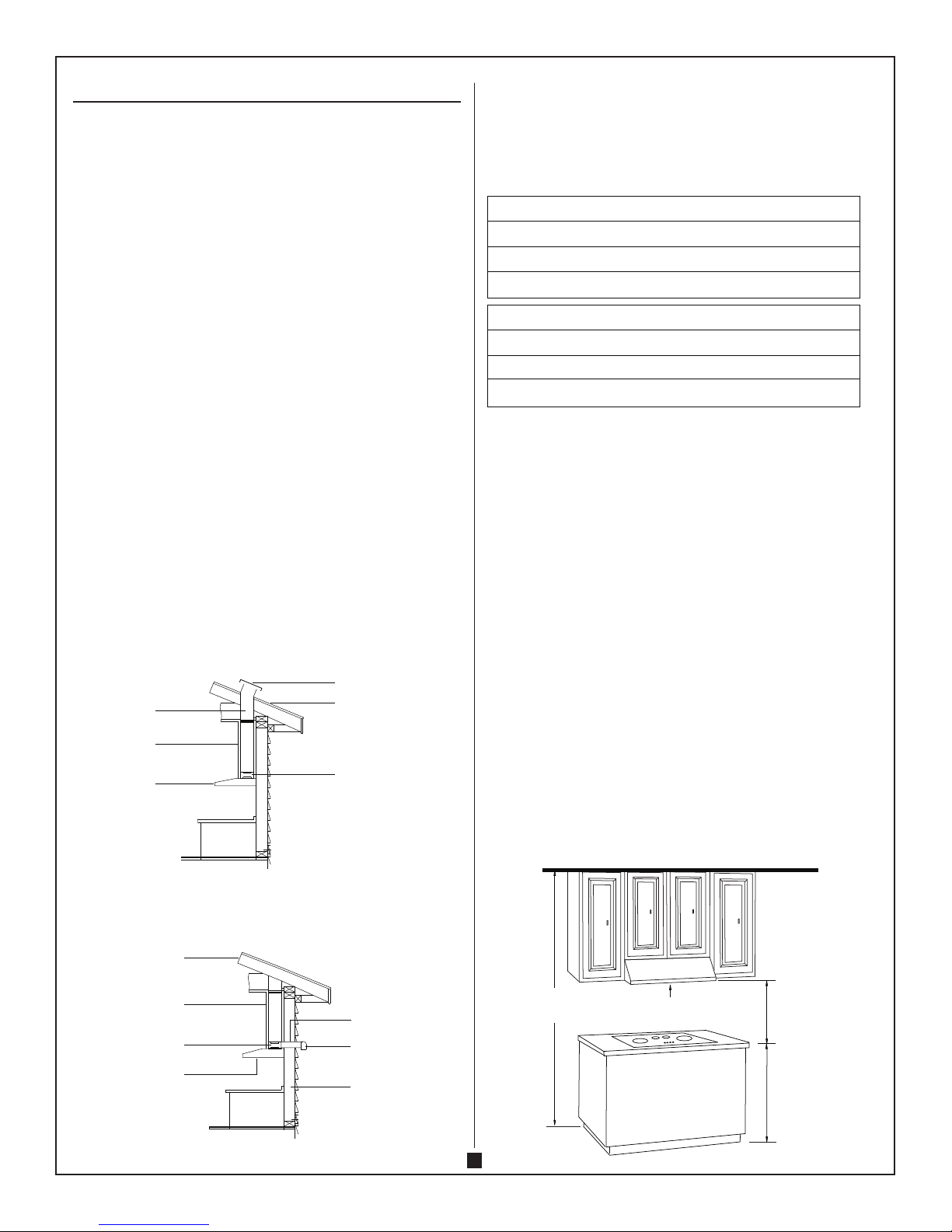
5. Thehoodisnotventingproperly:
- Makesurethedistancebetweenthecooktopandthebottomofthehood
isbetween18”to30”.
- Reducethenumberofelbowsandlengthofductwork.Checkifalljoints
areproperlyconnected,sealedandtaped.
- Makesurethepowerisonhighspeedforheavycooking.
- Windfromopenedwindowsordoorsinthesurroundingareaareaffecting
theventilationofthehood.Closeallwindowsanddoorstoeliminatethe
outsideairow.
- Checkifthedirectionofductopeningisagainstthewind.Ifso,adjustthe
directionoftheductopening.
- Checkifthewrongsizeofductsarebeingused.
6. Thelightdoesnotwork:
- Checktoseeiflightbulbisloose.Ifso,tighten.
- Removeproblembulbandinsertoneyouknowisworking.Iftheproperly
functioninglightdoesnotcomeon,theproblemmaybethelightassem-
bly.Serviceorreplacethelightassembly.
NOTE:Forallotherinquiries,pleasecontactusat:1-800-459-4409
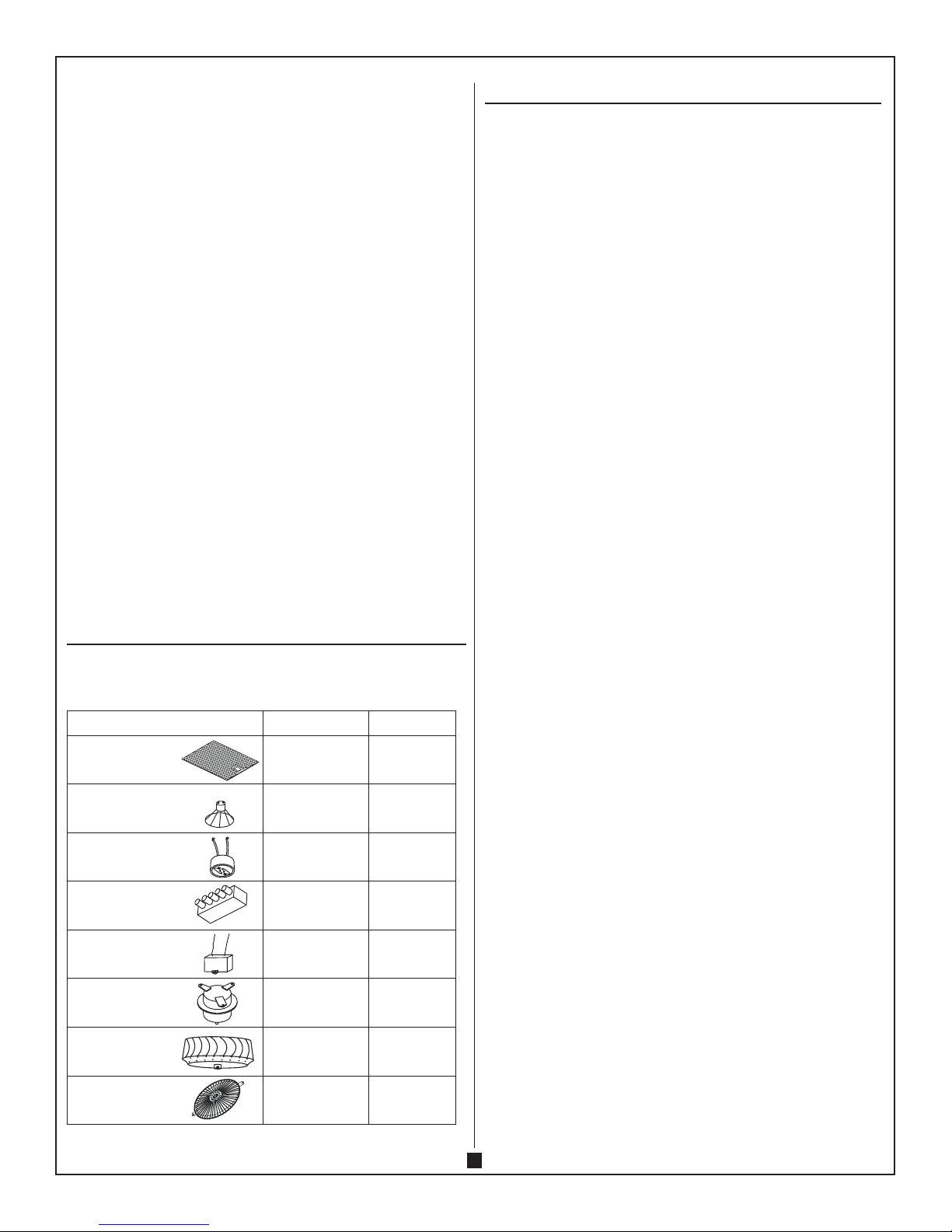
REPLACEMENT PARTS
Ifyouaremissingorrequirereplacementparts,pleasecallcustomerserviceat1-800-459-4409.
Identifytherequiredpart(s)andhavethereplacementpartnumberreadywhenyoucall.
DESCRIPTION PART CODE QUANTITY
Aluminum Net YL.JS.YW.09 2
GU10Light35W YL.DQ.DL.26 2
LightHolder
(GU10Base) YL.DQ.DZ.04 2
Switch
(5pushbuttontype) YL.DQ.KG.15 1
Capacitor YL.DQ.DR.07 1
Motor YL.DQ.DJ.25 1
Fan YL.DQ.FJ.06 1
SafetyNet YL.JS.YW.20 1
1-YEAR RESIDENTIAL WARRANTY
Thisproductiswarrantedtotheoriginalpurchasertobefreeofdefectsinmaterial
andworkmanshipforone(1)yearfromthedateofpurchase.Thiswarrantydoesnot
extendtocommercialorinstitutionaluseorinstallation.Warrantyserviceshouldbe
arrangedthroughthepointofpurchase.Thepurchaserisresponsiblefortransport-
ingtheunittoandfromthepointofpurchase.Incidentalrepairsthatwouldinvolve
aminimumoftimeandeffortonbehalfofthepurchaserwillnotbeconsidered
warrantyworkandnocompensationwillbedeemedforthcoming.Anyfailureofthe
unitthatisnottraceabletoadefectinmaterialorworkmanshipisnotcoveredbythis
warranty.Thesenon-warrantableitemsinclude,butarenotlimitedto:
• Changeincolorornishduetochemicalusage
• Theuseofabrasivecleansers
• Impropermaintenanceresultingfromfailuretoreasonablyclean,careforormaintaina
productinaccordancetoQualityCraft’scleaninginstructions
• Unitnotproperlyinstalledinaccordancewithmanufacturer’sinstructions
• Damagecausedduringshipping,handlingorinstallation
• Operating,maintenance,safetyguidelinesnotbeingfollowed
• Anyalterationstotheunit
• Damagetotheunitasaresultofaccidentalimpact,re,ood,freezing,normalwear
• Lightbulbsarenotcoveredbythiswarranty
• Scratches,chips,cracksorholescausedbyshipping,storageorinstallation
Athoroughinspectionmustbemadeattimeofpickupordelivery.Iftheunitisdam-
aged,aclaimmustbemadewiththecarrier.Reportanydamagepromptlyandprior
toinstallation.QualityCraftwillnotbeheldliableforanyfreightdamageordamage
causedbyleaksduetofreightdamage.Inspectionpriortoinstallationistherespon-
sibilityoftheinstaller,contractororuser.QualityCraftwillnotbeliableforfailuresor
damagethatcouldhavebeendiscoveredoravoidedbyproperinspectionandtesting.
QualityCraftwillnotbeheldliablefordamagesresultingfromtheimpropertorin-
stallationofproductsnotsuppliedbythiscompany.QualityCraftwillnotbeheldliable
forlossofuseofunit,inconvenience,costsincurredforlabour,materials,removaland
installationofreplacementunitsoranyotherincidentalorconsequentialdamages.
Costsrelatingtoobtainingaccessforrepairorreplacementaretheresponsibilityof
theuser.UndernocircumstanceshallQualityCraftoranyofitsrepresentativesbe
heldliableforinjurytoanypersonsordamagetoanyproperty.QualityCraftsobliga-
tionsshallbelimitedtotherepairorreplacementofaunit(atouroption)thatmay
prove,byoursoleexamination,tobedefectiveundernormaluseandserviceduring
thewarrantyperiod.TheCompanymayissuecreditintheamountoftheinvoicevalue
ofthedefectiveproduct(orapercentageofitaccordingtouse)inlieuofrepairor
replacement.AllreplacementsFOBQualityCraftnearestservicedepot.
QualityCraftwarrantyisnon-transferableandshallbevoidediftheunitisremoved
fromitsinitialinstallationorifitisnotinstalledfollowingthemanufacture’sspecica-
tions.Thiswarrantyshallnotapplytoanyproductthathasbeensubjecttoaccident,
alteration,misuse,abnormalchemicalconditions.Thiswarrantyismadeinlieuofall
otherwarrantiesexpressedorimplied.Nootherwarranty,expressedorimplied,is
assumedorwillbeassumed.
Importedby
QualityCraftKitchen&BathLtd.
Laval,Quebec,Canada,H7S2G7
TOLLFREETEL:1-800-459-4409
www.qualitycraft.com
MadeinChina

9
11/16"
29-13/16"
27-3/4
"
9-13/16"
1-1/2"
3-1/8"
1-1/8"
7/8"
dia. hole
7/8"
dia. hole
10-5/8"
18"
12"
2"
3-11/16"
2"
3/4"
4-5/16"
9-13/16"
3-1/8"
3/8"
29-13/16"
9"
3-11/16"
TOP VIEW
BACK VIEW
BlackBlack
Yellow/Green
Brown
White
Black
Gray
Yellow
Gray
Black
Blue
Yellow
Red
Black
Green
Yellow/Green
Black
White
MAX
35W/JDR 16
GU10
Light White
Motor
Capacitor
5µ F/370V
WIRING/DIMENSIONS
R6/03.10.11
Table of contents
Popular Ventilation Hood manuals by other brands

AEG
AEG DE 6261 user manual

Sirius Satellite Radio
Sirius Satellite Radio S-DDH3 Installation, Use and Maintenance Instruction

FALMEC
FALMEC Mira isola Instruction booklet

AIRLUX
AIRLUX HD74A-C-H manual

Lamona
Lamona LAM2300 User's installation guide

Siemens
Siemens LC67KFN60 User manual and installation instructions