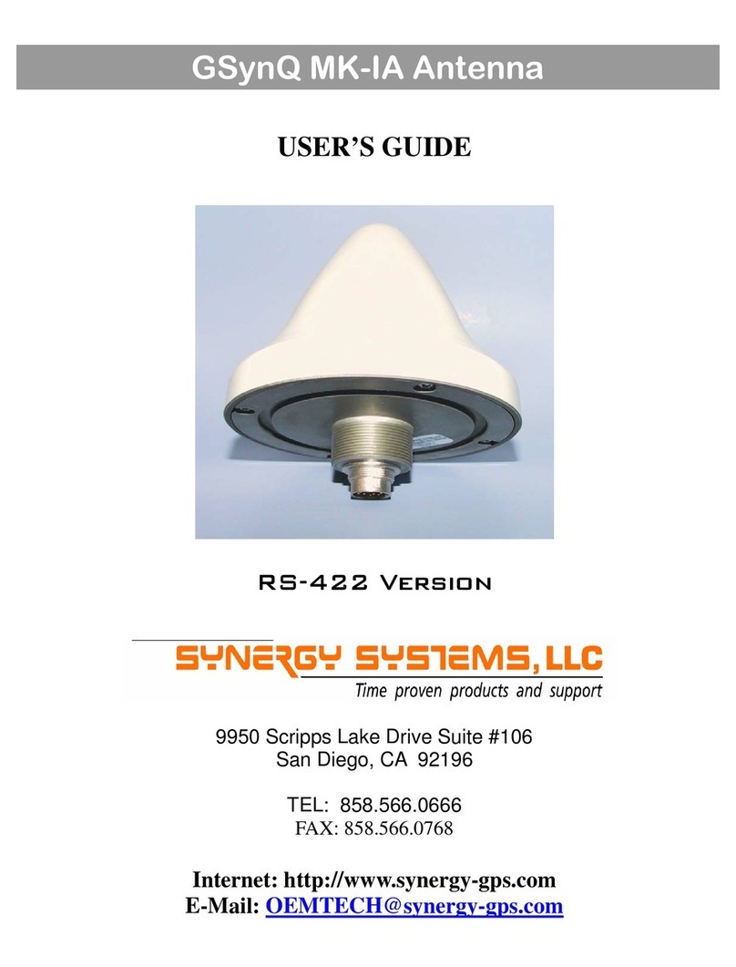
SYNERGY SYSTEMS G-SynQ User manual

10001507A 27NOV02
The user is referred at this point to the applicable Motorola
M12 ONCORE User’s Manual for details on operation of the
M12+ contained in the G-SynQ antenna.
Software—Windows based software to communicate with
the G-SynQ is available on the Synergy Systems website.
Motorola’s WinOncore12 program is a free download that
may be accessed from the home page. An evaluation copy
of Synergy’s SynTaC software is available from the Techni-
cal Support page of the website.
Support—If you have any problems at all, please do not
hesitate to contact Synergy’s technical support team, either
by the phone number on the front of this document, or by
email at: tech@synergy-gps.com
P.O. Box 262250 TEL: 858.566.0666
San Diego, CA 92196 FAX: 858.566.0768
Internet: http://www.synergy-gps.com
E-Mail: info@synergy-gps.com
G-SynQ Antenna Evaluation Kit
USER’S GUIDE

LIMITED WARRANTY
Synergy Systems, LLC warrants the G-SynQ Antenna
and Evaluation Kit Components against defects in mate-
rial and workmanship, under normal use and service, for
a period of one year from the product’s ship date from
Synergy Systems.
The M12+ GPS receiver contained in theG-SynQ Sensor
is trademarked and manufactured by Motorola, Inc.
(Motorola.)
Any returned product must be accompanied by a return
material authorization (RMA) number issued by Synergy
Systems. Deliver or send the product, transportation and
insurance prepaid, to:
Synergy Systems, LLC
9950 Scripps Lake Drive, Suite 106
San Diego, CA 92131 USA
TEL: (858) 566-0666
FAX:(858) 566-0768
GPS PERFORMANCE
The Global Positioning System (GPS) is operated and
supported by the U.S. Department of Defense and is
made available for civilian use solely at its discretion. The
GPS is subject to degradation of position and velocity
accuracies by the Department of Defense. Neither Syn-
ergy Systems nor Motorola warrant or control GPS avail-
ability or performance.
Copyright 2002, 2003 Synergy Systems, LLC
OPERATION
Operation of the G-SynQ Evaluation Kit is straight forward.
For operational details of the M12+ receiver contained in the
G-SynQ the user is referred to the M12 User’s Guide. Basic
connection details are as follows:
1 -The 2 meter serial cable is connected between the
Interface Assembly and the serial port on the host
computer.
2 -(Optional) The 2 meter 1PPS coax is connected
between the RCA jack on the back of the Interface
Assembly and whatever equipment is being used
to monitor the 1PPS pulse (oscilloscope, time inter
val analyzer, etc.)
3 -The 15 meter Interface cable is connected between
the G-SynQ antenna and the Interface Assembly.
The cable may be run in either direction, the
connectors on both ends are identical.
4 -The DC power plug is plugged into the Interface
Assembly, and then the power supply is plugged
into any convenient 110/240 VAC source. Note that
the power supply is supplied with four mains
connectors, allowing it to operate almost anywhere
in the world with the proper adapter installed.
As soon as power is applied, the PWR LED on the front
panel should illuminate. Also, the 1PPS LED will illuminate
for several seconds as the M12+ receiver goes through it’s
initialization routine. Once complete, the 1PPS LED will be-
gin flashing at a nominal 1 Hz rate. Note that this 1PPS out-
put is generated by the internal real time clock and will not
be accurate until the receiver has achieved a fix. It is, how-
ever, an indication that the system is hooked up properly
and that the receiver is going through its’ normal house-
keeping routines.

POWER/DATA INDICATORS
Behind the IR transparent front panel of the Interface As-
sembly are four LEDs which serve to alert the user to cur-
rent system status. The four LEDs are described briefly as
follows:
PWR -Illuminated whenever the internal +5V supply is
present.
TxD -Briefly flashes whenever data is being transmitted to
the host computer from the G-SynQ antenna.
RxD -Flashes whenever commands are sent from the
host to the G-SynQ.
NOTE: If this LED is illuminated continuously, the
serial link between the host computer and the
Interface Assembly is probably disconnected.
Check the cabling carefully.
1PPS -Flashes whenever the 1PPS pulse is transmitted by
the G-SynQ antenna.
NOTE: Timing versions of the M12+ receiver
support a 100 PPS output option. If the 100PPS
pulse option is selected by the user, this LED will
appear to be glowing constantly at decreased bright
ness as the eye cannot follow the 100PPS switch-
ing of the LED.
PRODUCT DESCRIPTION
The G-SynQ Evaluation Kit comprises all of the components
necessary for the system integrator to evaluate the perform-
ance of the Synergy Systems G-SynQ antenna. These
components include the G-SynQ antenna itself, an Interface
Electronics Assembly that supplies power to the antenna
and provides RS-232 to RS-422 level translation, a 15 meter
Interface Cable, DC power supply, and associated intercon-
nect cabling.
G-SynQINTERFACE ASSEMBLY
PHYSICAL CHARACTERISTICS
Size: 5.0” W x 5.3”L x 1.5”H
(127mm x 135mm x 38mm)
Weight: 6 oz (0.2 kg)
Housing: Cycolac
ELECTRICAL INTERFACE
Power: 2.1mm Coaxial DC
Data: DB-9F Connector
G-SynQ Antenna: Deutsch MMP26
1PPS Out: RCA Phono Jack
ENVIRONMENTAL CONDITIONS
Operating Temp: -20oC to +55oC
Storage Temp: -40oCto +65oC
Relative Humidity: 10% to 90%, non-
condensing
POWER REQUIREMENTS
+9 to +30VDC (250 mA max)

POWER/DATA INTERFACE
The G-SynQ Evaluation Kit is supplied with a wall-mounted
DC power supply and all required interconnect cables. The
power supply is rated at 12VDC (unregulated) and is suffi-
cient to power the antenna through up to approximately 75
meters of the type of cable supplied in the Evaluation Kit. If
longer cable lengths are utilized, the power supply voltage
may be increased up to a level of 30VDC to allow for the ex-
tra IR drop in the Interface Cable. The power connector on
the rear panel of the Interface Assembly is a standard
2.5mm coaxial DC power connector (center pin positive.)
In the event that the unit is accidentally shorted, a self-
resetting polymer fuse opens, protecting the Interface Elec-
tronics and G-SynQ antenna from possible damage. Once
activated, the fuse should be allowed to cool for several
minutes before power is reapplied.
SERIAL PORT -User interface with the G-SynQ antenna is
accomplished through the DB9 connector located on the
housing endplate. The serial port extension cable supplied
with the Evaluation Kit is used to connect the Interface As-
sembly to the host computer serial port. All communications
on this connector occur at nominal RS-232 levels. For refer-
ence, Interface Assembly connector pinouts are as follows:
Rear Panel View of the Interface Assembly Showing
Connector Placement.
PIN SIGNAL
Pin 1 1PPS (To Host)
Pin 2 TxD (Data To Host)
Pin 3 RxD (Data to G-SynQ)
Pin 5 Signal Common
1PPS -The 1PPS signal from the G-SynQ antenna is pre-
sent on the RCA phono jack located on the back panel of
the Interface Assembly. The Evaluation Kit is supplied with a
2meter long coaxial 1PPS monitoring cable terminated in a
standard RCA plug on one end, and a BNC plug on the
other. The 1PPS signal is internally buffered by an “ACT”
series CMOS inverter with a 27 ohm resistor in series with
the output lead. Due to the extremely fast rise time of the
pulse (10 nS) the BNC connector should be terminated into
50 ohms in order to minimize reflections in the cable.
The Evaluation Kit is normally supplied with the 1PPS out-
put as a positive going pulse. If desired by the user, the
1PPS pulse may be switched over to a negative going pulse
by removing the top of the Interface Assembly and moving
the jumper strip at position JP1 on the printed circuit board
to the alternate location.
Also, when calculating the offset of the 1PPS output, the
propagation delay through the CMOS buffers on the inter-
face PWA should be considered. A negative going 1PPS
will exhibit approximately a 6 nS delay (1 buffer section)
while a positive going pulse will exhibit a delay of approxi-
mately 12 nS (2 buffer sections.)
Other SYNERGY SYSTEMS Antenna manuals