Before Installation
Please thoroughly read this guide and applicable sections of OSID Global
Application Note, document no. (25686). This manual is available online at
www.systemsensor.com.
General Description
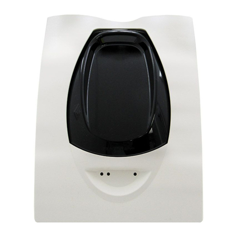
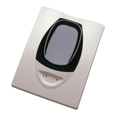
The OSI- RE- SS is a long range projected beam smoke imaging detector
designed to provide open area protection. It is to be used with listed (UL,
EN54 , etc.), It is to be powered from a CE Certified AC/DC Power
converters to be in compliance for CE certification. The detector consists of a
transmitter/receiver unit and a reflector. Smoke entering the area between the
transmitter/receiver and reflector causes a reduction in signal. When the
obscuration reaches the alarm threshold (automatically set at the
transmitter/receiver unit), the detector generates an alarm signal. Complete
blockage of the beam causes a trouble signal. Slow changes in obscuration due
to a build-up of dirt or dust on the lens of the detector are compensated for by
a Microcontroller that continuously monitors the signal strength and
periodically updates the alarm and trouble thresholds. When the self-
compensation circuit reaches its limit, the detector generates a trouble signal,
indicating the need for service.
Three LEDs on the detector indicate the current status: a red LED for alarm,
a yellow LED for trouble, and a blinking green LED for standby operation.
The alarm signal latches and can be reset by a momentary power interruption
or by activating the remote reset input to the detector if using the remote
test/reset station model RTS151KEY.
The yellow LED will blink in specific patterns to provide a diagnostic aid
when diagnosing the cause of a trouble signal. Trouble signals automatically
reset upon removing the cause of trouble. Red and yellow LEDs can be
remotely connected to the remote Alarm and Trouble outputs. These outputs
mimic the functions of the detector’s red and yellow LEDs.
After commissioning the 4 arrows will indicate the level of automatically set
sensitivity.
Each detector contains one change over relay contact for alarm signals and
one change over relay contact for trouble signals. The trouble relay is fail
safe and will open if power is removed from the detector. Thus, an additional
EOL power supervision relay is not necessary.
The trouble contacts from all the beam detectors on one initiating circuit must
be connected after the last indicating device on the loop. This prevents a
single beam detector in trouble from disabling other initiating devices on the
same loop.
Special Applications
Due to the inherent capabilities of projected type beam detectors they are
often installed in locations where spot-type detection is impractical. Projected
type beam smoke detectors are ideally suited for environmental conditions that
might include high ceilings or areas with difficult access to the ceiling. Often
these conditions present special problems for the installation of spot- type
detectors and even greater problems for their proper maintenance. Due to the
inherent flexibility of mounting locations and large coverage area of projected
type beam detectors often the conditions above can be addressed or
minimized. Some examples of applications for beam detectors might include
aircraft hangars, cold storage warehouses, shipping warehouses, enclosed
parking facilities, sporting arenas and stadiums or concert halls. Some of these
environments might be considered not suitable for spot-type smoke detectors.
Before installing the transmitter/receiver unit or reflector in these types of
applications special consideration should be given to ensure proper operation
of the beam detector. The beam detector should not be installed in
environments where heavy condensation or icing is likely. Condensation or
icing of the reflector surface or the outer surface of the transmitter/receiver
unit will obscure the light beam resulting in a nuisance alarm. If elevated
humidity levels and rapidly changing temperatures can be expected then
condensation will likely form and the application should not be considered
acceptable for the beam detector.
In environments where a mild condensation is expected, the standard on-board
lens heaters can be initiated by activating the heating switch located in the
detector.
The beam detector should not be installed in locations where the
transmitter/receiver unit, the reflector, or the optical pathway between them
may be exposed to outdoor conditions such as rain, snow, sleet, or fog.
These conditions will impair the proper operation of the detector and must be
avoided.
Approved Accessories
The following accessories can be purchased separately for use with this beam
detector.
6500MMK
The 6500MMK allows reflected
beam detectors and reflectors to be
mounted to either a vertical wall or
the ceiling. The kit allows for
additional alignment range in cases
where the detector and reflector
cannot be mounted within 10° of each
other. The kit includes the hardware
necessary to mount either a single
transmitter/receiver unit or a single
reflector.
BEAMHKR
The BEAMHKR allows the reflector
to operate in environments prone to
the formation of condensation.
Condensation forming on the
reflector may result in trouble or
false alarm conditions. BEAMHKR
will lessen the likelihood of
condensation by maintaining the
reflector at a temperature that is
slightly higher than surrounding air.
The kit requires a 24V power supply.
RTS151KEY (Test Function)
The remote test accessory allows for
the beam detector to be tested and
reset remotely from ground level.
The test accessory provides test and
reset functions and green and red
LEDs that mimic the LEDs on the
detector.
Package Contents
l1 Transmitter/Receiver Unit
l1 Paintable Trim Ring
l1 Reflector
l4 Plug-in Terminal Blocks
l1 OSI-RE-SS Quick Start Guide
6 E56-6654-000
