Dorma TS 99 FLR-K Manual

DORMA
DORMA TS 99 FLR-K EN 2-5
Montage der Festellanlage FLR-K wenn die Unter-
fläche der Decke auf einer oder auf beiden Seiten
der Tür weniger als 1 m über der Sturzunterkante
liegt. 1)1)
1)1)
1)
Entsprechende Anschlußpläne siehe separates Blatt.
Ist die Unterfläche der Decke auf einer oder auf bei-
den Seiten der Tür mehr als 1 m über der Sturzunter-
kante, sind zusätzlich zum Sturzmelder (FLR-K) zwei
Deckenmelder anzubringen. 1)1)
1)1)
1)
Entsprechende Anschlußpläne siehe separates Blatt
.
Befestigungspunkte für Schließer und Gleitschiene
nach Schablone TS 99 FLR-K oder nach Maßbild
bohren.
Für bauseitige Stromzuführung 230 V AC Ø 12 und
für die Verbindung zum TS 99 FL, Handtaster und
evtl. benötigten Deckenmeldern Ø 10 mm bohren und
Kabel legen.
Verteilerdose anschrauben.
Montageplatte anschrauben.
Schließer auf die Montageplatte schrauben.
Darauf achten, daß das Kabel in der Nut der
Montageplatte liegt und nicht beschädigt wird.
In der Verteilerdose die Kabel der Spannungs-
zuführung 24 V DC anklemmen .
Verbindungskabel aufstecken .
Internes Verbindungskabel mit dem Stecker der
elektrohydraulischen Feststellung verbinden .
Hebel ca. 10° zum Türblatt aufsetzen und festschrauben.
DIN-L
FLR-K Einheit anschrauben.
DIN-R
Gleitschiene um 180° drehen .
FLR-K Einheit anschrauben.
Ventil zur Regulierung der Schließgeschwindigkeit
schließen und Tür ca. 45° öffnen .
Hebel in Richtung Gleitschiene drücken und mit
Gleitstück verbinden .
Schließkraft einstellen.
Schließgeschwindigkeit 180°- 0° einstellen .
Endschlag 7°- 0° einstellen .
Endkappen aufstecken .
Achsausnehmung ausbrechen und Verkleidung
aufklipsen .
Darauf achten, daß die Kabel nicht beschädigt werden.
DORMA Logo aufklipsen .
MONTAGEANLEITUNG
Technische Daten TS 99 FLR-K
Eingang: 230 V AC +10%/-15%
120 mA/28 VA / 50 Hz
Ausgang: 24 V DC /460 mA / 11 W
Schutzart: IP 30
Schutzklasse: II
Rauchschalter: 24 V DC/50 mA
Temperatur: -20°C/+60°C
Technische Daten EMF
Betriebsspannung: 24 V DC
Leistungsaufnahme: 2 W
Einschaltdauer: 100 % ED
• Arbeiten an Elektroanlagen dürfen nur von
geschulten Fachkräften ausgeführt werden.
• Überprüfen, ob die bauseitige Stromzuführung
(230 VAC) spannungslos geschaltet ist.
• Im Versorgungskreis muss ein Sicherungsautomat
10A/B vorhanden sein. Dieser dient gleichzeitig als
Trennvorrichtung, um den FLR-K spannungsfrei zu
schalten.
• Zur Zugentlastung muss die Netzzuleitung vor dem
FLR-K ausreichend befestigt werden.
• Der Querschnitt der Netzzuleitung (NYM) darf max.
1,5 mm2betragen. Der Schutzleiter wird nicht elek-
trisch verwendet. Die Klemme (PE) ist aber bei
vorhandenem Schutzleiter zu verwenden.
• Brandmelder von Feststellanlagen dürfen keine
weiteren Alarmierungseinrichtungen (z.B. Über-
tragungseinrichtungen für Brandmeldungen)
ansteuern. 1)
• Wird als Option das Alarmmodul verwendet, ist das
Verbindungskabel zum Rauchschalter über die
Messkammer zu führen um die Raucheindringung
nicht zu behindern.
• Nach den Richtlinien für Feststellanlagen des
Instituts für Bautechnik, Berlin, muss jede
Feststellvorrichtung auch von Hand ausgelöst
werden können.
Werden Freilauftürschließer verwendet, muss die
Auslösung über einen Taster erfolgen.
Der hierfür verwendete Handauslösetaster muss rot
sein und die Aufschrift “Tür schließen” tragen. Der
Taster muss sich in unmittelbarer Nähe des Ab-
schlusses befinden und darf durch den festgestell-
ten Abschluss nicht verdeckt sein.
Rauchmeldezentrale
Elektromagnetische Feststellvorrichtung
Rauchmelder
DORMA HT - Handauslösetaster für Feststell-
vorrichtungen.
1)1)
1)1)
1) Richtlinien für Feststellanlagen des
Deutschen Instituts für Bautechnik, Berlin
a
b
1
2
3
4
5
6
7
8
9a
9b
10
11
12
13
14
☞
☞
☞
WN 057718 45532
01/10

DORMA TS 99 FLR-K EN 2-5
3
12
14
1+
4–
2
10
7NO
8NC
9C
11
16
Anschluss externe
Melder mit Abschluss-
widerstand 2)
Ausgang 24 V DC
Feststellvorrichtung(en)
Externe Handauslösung
mit Abschlusswiderstand 2)
Potentialfreier Wechsler
Kleinspannung (SELV)
24V AC/DC, 2A
Potentialfreie Klemme
Bus
Gesamt-
Ausgangsleistung
max. 9,8 W
2)
siehe Anschlusspläne
Klemmenbelegung FLR-K
Handtaster anschließen und eventuell vorhandene
Deckenmelder anschließen - siehe Anschlußpläne.
Abschlusswiderstände beachten!
RS-Alarmmodul (Option) einsetzen und anklemmen.
Das Alarmmodul kann nicht verwendet werden, wenn
die Relaiskontakte 7,8,9 bereits belegt sind.
Um die Schutzklasse II (Schutzisolierung) einzu-
halten, ist die 230 V Zuleitung doppelt isoliert bis zur
Anschlußklemme zu verlegen.
Kabel abisolieren.
Kabel für die Stromzuführung anklemmen .
Berührungsschutz schließen und zuschrauben .
Reset (Wiederscharfschaltung)
Betriebsanzeige blinkt grün, sobald kein Rauch bzw.
Prüfgas mehr in der Rauchkammer ist.
Die Wiederscharfschaltung erfolgt über den Reset
Taster.
Beiliegendes „RESET“ Etikett auf die Verkleidung
kleben.
Rote Schutzhaube von der Rauchmeldeeinheit
entfernen .
Spannung anlegen - Betriebsanzeige blinkt grün .
Reset Taster drücken - Betriebsbsanzeige leuchtet
grün.
Freilauffunktion einstellen
Schalter der Verteilerdose auf "EIN" stellen
(24V DC für Feststellvorrichtung) .
Türflügel auf die gewünschte Feststellposition
öffnen . Die Schließerachse wird in dieser Position
über die elektrohydraulische Feststellvorrichtung ge-
halten, die Tür kann jedoch über die Freilauf-
funktion im Hebel frei bewegt werden.
Tür offen stehen lassen.
Funktionsprüfung Handtaster
Stromzufuhr über Handtaster (z.B. DORMA HT)
unterbrechen . Die Feststellvorrichtung wird strom-
los geschaltet und die Tür wird geschlossen .
Betriebsanzeige blinkt grün. Die Wiederscharf-
schaltung erfolgt über den Reset Taster . Betriebs-
anzeige leuchtet grün.
Endkappenblenden aufclipsen .
Markierte Aussparung an der Verkleidung ausbrechen .
Verkleidungen aufclipsen .
15
16
17
18
19
20
21
Änderungen vorbehalten
Funktionsprüfung
Anwendungs- und Sicherheitshinweise auf dem
Prüfgas und Sicherheitsdatenblatt beachten.
Türflügel öffnen .
Prüfgas (Hekatron 918/5) aus ca. 10-15 cm
Entfernung in Richtung Rauchkammer sprühen .
Nach ca. 4-6 kurzen Sprühstößen schaltet die
Betriebsanzeige auf Alarm (rot) um. Ist der FLR-K mit
dem RS-Alarmmodul (Option) ausgestattet wird der
Alarm auch akustisch angezeigt.
Die Feststellvorrichtung wird stromlos geschaltet und
die Tür wird geschlossen .
Betriebsanzeige blinkt grün, sobald kein Rauch bzw.
Prüfgas mehr in der Rauchkammer ist.
Die Wiederscharfschaltung erfolgt über den Reset
Taster . Betriebsanzeige leuchtet grün.
Mitgelieferte Staubschutzhaube aufstecken, damit
während weiterer Rohbauarbeiten kein Staub in den
Rauchmelder gelangt.
Vor der endgültigen Inbetriebnahme ist die
Staubschutzhaube zu entfernen und eine weitere
Funktionsprüfung gemäß Punkt 22 durchzuführen.
Funktionen der LED’s
LED an LED aus
Betriebsanzeige LED 1 (grün/rot)
Betrieb: grün
Alarm: rot
Handreset erforderlich: blinkt grün
(siehe auch Punkt 17)
Wartungsanzeige LED 2 (gelb)
Fällige Wartung: blinkt
Verschmutzung: blinkt
Störung: Dauer
ABNAHMEPRÜFUNG UND WARTUNG
Merkblatt über die Verwendung von Feststellanlagen..
..
.
Wird der Sturzmelder FLR-K in Räumen mit großem
Staubanfall eingesetzt, sind die vorgeschriebenen
Wartungsintervalle unbedingt einzuhalten, oder ggf.
sogar zu verkürzen, da Staubablagerungen im Melder
zu Fehlauslösungen führen können.
EN 14600 Anhang C
WEITERE HINWEISE / VORSCHRIFTEN
Zulassungsbescheid
Merkblatt über die Verwendung von Feststellanlagen.
Richtlinien für Feststellanlagen des Deutschen
Instituts für Bautechnik, Berlin.
22
23
24
☞
☞
DORMA GmbH + Co.KG DORMA Platz 1 D-58256 Ennepetal • Tel. +49 (0) 23 33 / 793-0 • www.dorma.com
Door Control Division Postfach 40 09 D-58247 Ennepetal • Fax +49 (0) 23 33 / 79 34 95
☞
☞
☞

DORMA
DORMA TS 99 FLR-K EN 2-5
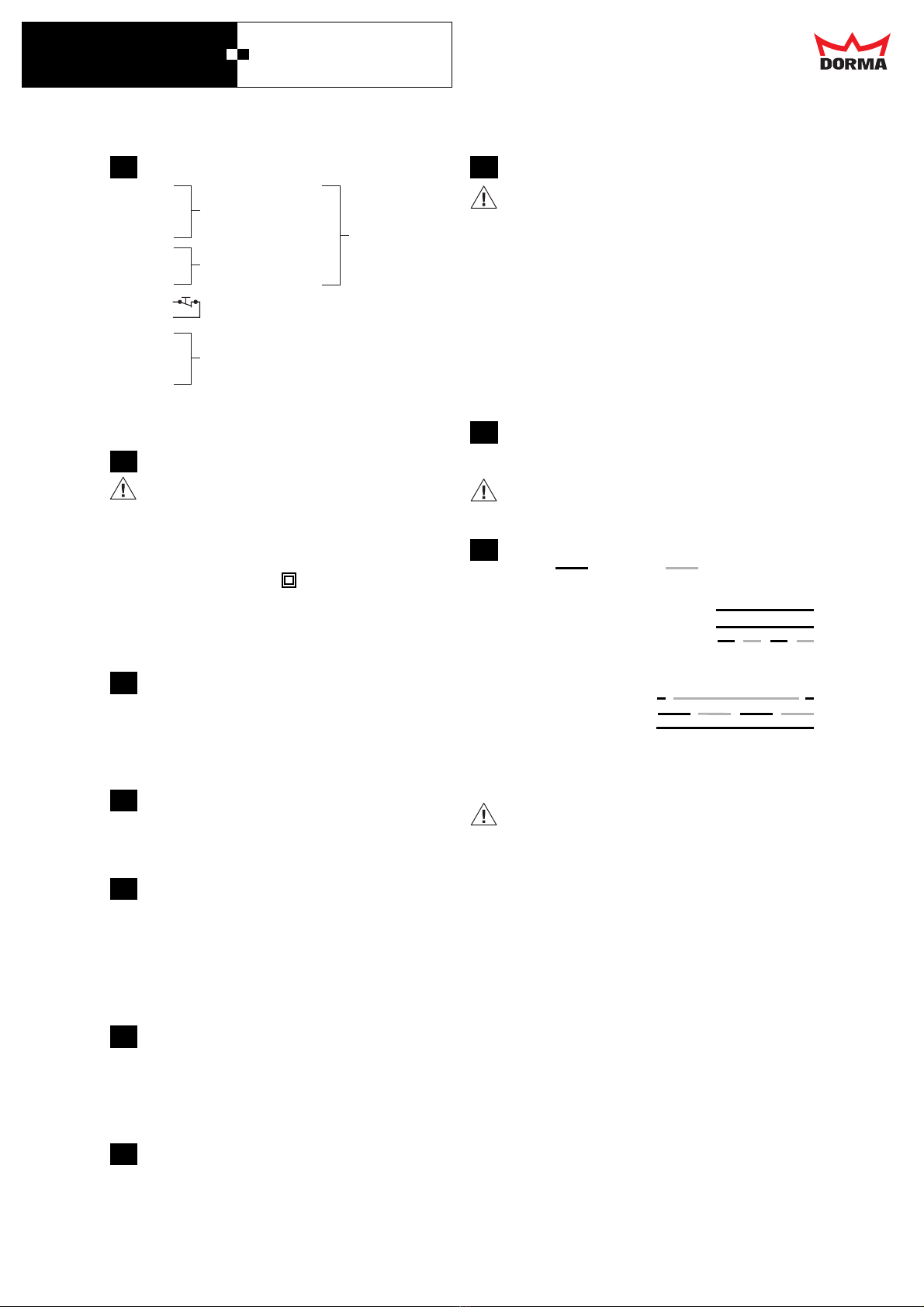
Installation arrangement of the FLR-K for
applications where the bottom surface of the ceiling
is less than 1m above the bottom edge of the lintel
on one or both sides of the door. 1)1)
1)1)
1)
See separate sheet for associated connection
diagrams.
If the bottom surface of the ceiling is more than 1m
above the bottom edge of the lintel on one or both
sides of the door, two ceiling-mounted smoke
detectors must be installed in addition to the lintel-
mounted detector (FLR-K) 1)1)
1)1)
1)
See separate sheet for associated connection
diagrams.
Drill fixing points for closer and slide channel using
TS 99 FLR-K template or as per dimensioned
drawing.
Drill holes of 12 mm dia. for the 230V AC power
cable (by others) and of 10 mm for connection to the
TS 99 FL, manual pushbutton and any required
ceiling-mounted detectors. Install cabling.
Fix junction box.
Fix mounting backplate.
Fix closer to the mounting backplate.
Ensure that the cable is located in the mounting
backplate groove and that it remains undamaged.
Connect 24V DC supply cable to the junction box
terminal .
Connect interconnecting cable .
Connect the internal cable to the connector of the
electro-hydraulic hold-open device .
Fit arm at an angle of approx. 10° from the door leaf
and tighten fixing screw
LH (ISO 6) handing:
Fix FLR-K unit.
RH (ISO 5) handing:
Rotate slide channel 180° .
Fix FLR-K unit.
Close valve for adjusting closing speed , and open
door approx. 45° .
Push arm towards slide channel and connect to
slide block .
Adjust spring strength (closing force).
Adjust closing speed 180° - 0° .
Adjust latching action 7° - 0° .
Fit end caps .
Break out spindle recess tab and fit clip-on cover .
Ensure that the cables are not damaged in this
process.
Clip on DORMA logo badge .
FIXING INSTRUCTIONS
Technical Data TS 99 FLR-K
Input: 230 V AC +10%/-15%
120 mA/28 VA / 50 Hz
Output: 24 V DC /460 mA / 11 W
Type of Protection: IP 30
Protection class: II
Smoke switch: 24 V DC/50 mA
Temperature: -20°C/+60°C
Technical Data, Hold-open Device (EMF)
Operating voltage: 24 V DC
Power input: 2 W
Duty factor: 100 % continuous duty
• Work on electrical equipment and systems may
only be performed by properly trained specialist
personnel.
• Check to ensure that the line power supply (230V
AC) has been disconnected and is no longer live.
• IA 10 A/B miniature circuit breaker must be
provided in the supply circuit. This can also be
used as the isolator for disconnecting the FLR-K
and making it dead.
• The power cable leading to the FLR-K must be
properly secured to ensure effective strain relief.
• The power cable (NYM) conductor cross section
should be not greater than max. 1.5 mm2The PE
conductor is not electrically utilised. The terminal
(PE) should, however, be used where a PE
conductor is provided.
• Fire/smoke detectors controlling hold-open
systems must not be used to actuate any further
alarm devices (e.g. fire alarm transmission
systems). 1)
• If the optional alarm module is installed, the cable
connecting it to the smoke switch must be led over
and across the measurement chamber in order to
ensure that smoke penetration is in no way
hindered.
• According to the guidelines for hold-open systems
issued by the Institute of Building Technology,
Berlin, it must be possible to release every hold-
open device by manual means. If free-swing door
closers are used, release must be initiated by a
manual pushbutton. The manual release
pushbutton used for this must be red and carry the
inscription “Close Door”. The pushbutton must be
in the immediate vicinity of the door (barrier) and
must not be concealed when the door (barrier) is
open.
Integral lintel-mounted smoke detector.
Electro-magnetic hold-open device.
Ceiling-mounted smoke detector.
DORMA HT manual release pushbutton for hold-
open devices.
a
b
1
2
3
4
5
6
7
8
9a
9b
10
11
12
13
14
☞
☞
☞
1)1)
1)1)
1) Guidelines for hold-open systems issued by the Institute for Building Technology,
Berlin. In countries outside Germany, consult local regulations.
WN 057718 45532
08/09

DORMA TS 99 FLR-K EN 2-5
Terminal assignment FLR-K
Connect manual pushbutton and any required ceiling-
mounted detectors – see connection diagrams.
Terminal resistors must be properly installed!
Insert and connect RS smoke alarm module (option).
The alarm module cannot be used if relay contacts
7, 8 and 9 are already in use.
In order to comply with protection class II (total
insulation), the 230V power cable should be installed
with double insulation up to the connection terminal.
Remove cable insulation at the end.
Connect power cable to terminals .
Close the shock hazard protection cover and screw
down .
Reset
Status display flashes green as soon as there is no
longer any smoke or test gas in the smoke chamber.
Reset is performed by pressing the reset pushbutton.
Attach the enclosed RESET label.
Remove the red protective cap from the smoke
detector unit.
Switch on power supply – status display flashes green .
Press the RESET pushbutton – status display
should show green.
Setting the free-swing function
Set the switch in the junction box to “ON”
(24V DC for hold-open device) .
Open the door leaf to the required hold-open position .
The closer spindle is held in this position by the
electro-hydraulic hold-open device, but the door can
be freely moved thanks to the free-swing arm
assembly.
Leave the door open.
Functional test of manual pushbutton
Interrupt power supply using manual pushbutton (e.g.
DORMA HT) . The hold-open device is de-energised
and the door is closed .
Status display flashes green.
Press the RESET pushbutton . – status display
should show green.
Clip on end caps .
Break out the tab as marked for the recess in the
cover .
Clip on cover .
15
16
17
18
19
20
Functional checks
Ensure compliance with the instructions for use and
also the safety instructions provided on the test gas
container and safety datasheet.
Open door leaf .
Spray test gas (Hekatron 918/5) from a distance of
approx. 10-15cm towards the smoke chamber .
After approx. 4-6 short bursts, the status display
should switch to alarm (red). If the FLR-K is equipped
with the RS smoke alarm module (option), an audible
alarm is also sounded.
The hold-open device is tripped and released, and the
door closes .
Status display flashes green as soon as there is no
longer any smoke or test gas in the smoke chamber.
Reset is performed by pressing the RESET pushbutton .
Status display should show green.
Fit dust protection cover supplied so that dust is
prevented from entering the smoke detector during
any subsequent building or finishing work.
Prior to final commissioning, remove the dust
protection cover and perform a further function
check in accordance with step 22.
Function of the LEDs
LED on LED off
Status display LED 1 (green/red)
Standby: green
Alarm: red
Manual reset necessary: green flashing
(see also item 17)
Service display LED 2 (yellow)
Servicing due: flashes
Contamination: flashes
Fault: continuous
FINAL INSPECTION AND MAINTENANCE
Instruction sheet relating to the use and application
of hold-open systems.3)
If the FLR-K lintel-mounted smoke detector is used in
rooms with a high dust content, ensure compliance
with the specified maintenance intervals. These may
even have to be reduced in order to ensure that dust
deposits in the detector do not give rise to nuisance
tripping.
EN 14600 Appendix C
FURTHER INFORMATION / REGULATIONS
Approval certificate
Instruction sheet relating to the use and application
of hold-open systems.3)
Guidelines for hold-open systems published by the
Institute for Building Technology, Berlin 3), or
equivalent national guidelines
22
23
24
☞
☞
DORMA GmbH + Co.KG DORMA Platz 1 D-58256 Ennepetal • Tel. +49 (0) 23 33 / 793-0 • www.dorma.com
Door Control Division Postfach 40 09 D-58247 Ennepetal • Fax +49 (0) 23 33 / 79 34 95
☞
☞
☞
3) These documents are only printed in German as they refer
exclusively to the German market.
Subject to change without notice
Table of contents
Languages:
Other Dorma Smoke Alarm manuals