SYSTRONIK EUROLYZER ST User manual

SYSTRONIK
Elektronik u. Systemtechnik GmbH
Gewerbestrasse 57
D-88636 Illmensee
Tel.: +49 (0) 7558 / 9206-0
Fax: +49 (0) 7558 / 9206-20
E-Mail: info@systronik.de
Internet: www.systronik.com
Read manual before use!
Observe all safety information!
Keep manual for future use!
11.2011 0 Systronik-Artikel-Nr.: 22794
854.001.0475
Instruction Manual
Flue Gas Analysis Computer
EUROLYZER® ST
EUROLYZER® STe

2 EUROLYZER® ST / STe
Contents
1
About this instruction manual ..................................................................................4
1.1
Structure of warning.....................................................................................4
1.2
Explanation of symbols and typeface ..........................................................4
2
Safety.......................................................................................................................5
2.1
Intended use.................................................................................................5
2.2
Predictable incorrect application..................................................................5
2.3
Safe handling ...............................................................................................5
2.4
Qualification of personnel.............................................................................6
2.5
Modifications to the product.........................................................................6
2.6
Usage of spare parts and accessories.........................................................6
2.7
Liability information ......................................................................................6
3
Product description..................................................................................................6
3.1
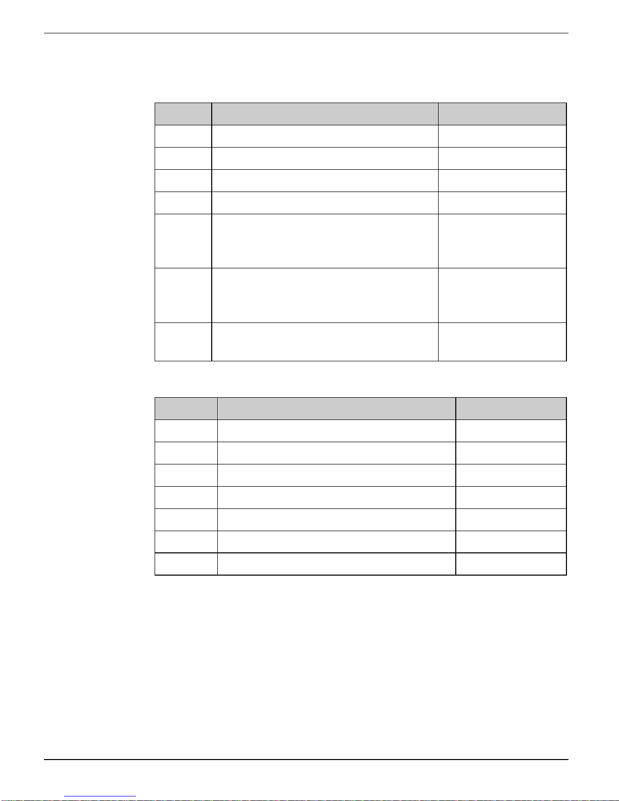
Control panel (buttons and scroll function) ..................................................7
3.2
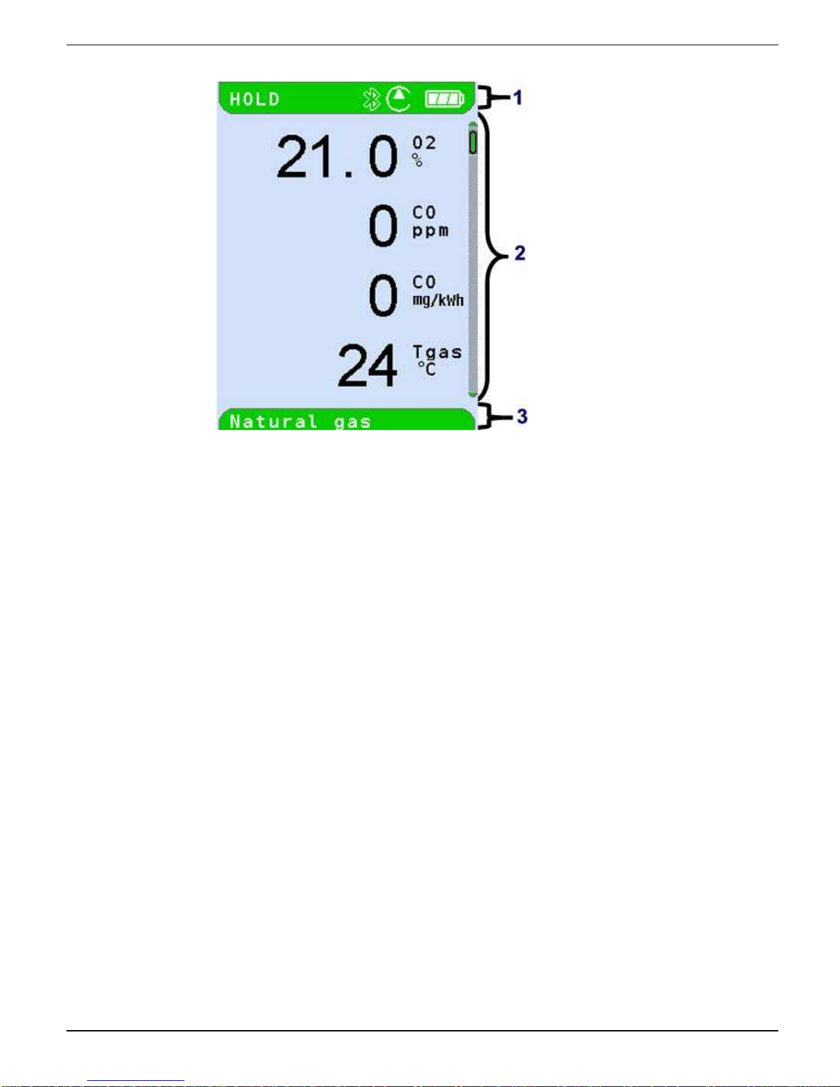
Display..........................................................................................................8
3.3
Measurement and calculation parameters.................................................10
3.4
Measuring methods....................................................................................11
4
Technical specifications.........................................................................................11
4.1
Calculation formulae (extract)....................................................................14
4.2
Approvals, tests and conformities..............................................................15
5
Transportation and storage ...................................................................................15
6
Commissioning......................................................................................................16
6.1
Connection diagram...................................................................................16
7
Program start.........................................................................................................17
8
Measuring programs and Settings menu ..............................................................18
8.1
"Flue gas measurement" program .............................................................18
8.2
"Temperature measurement" program.......................................................31
8.3
"Pressure measurement" program.............................................................32
8.4
"Settings" configuration menu....................................................................33
9
Memory mode & memory structure (option)..........................................................34
9.1
How to save................................................................................................39
10
Battery management.............................................................................................40
10.1
Battery mode/charging mode.....................................................................40
10.2
Charging the batteries................................................................................40
11
Maintenance..........................................................................................................42
12
Troubleshooting.....................................................................................................42
13
Shutting down and disposal ..................................................................................44

EUROLYZER® ST / STe 3
14
Spare parts and accessories.................................................................................44
15
Warranty................................................................................................................45
16
Copyright ...............................................................................................................45
17
Customer satisfaction............................................................................................45
18
Addresses..............................................................................................................45
19
Appendix................................................................................................................46
19.1
Bluetooth Declaration of Conformity ..........................................................46
19.2
DIN EN 50379 Certificate...........................................................................47

About this instruction manual SYSTRONIK
4 EUROLYZER® ST / STe
1 About this instruction manual
This instruction manual is part of the product.
Read this manual before using the product.
Keep this manual during the entire service life of the product
and always have it readily available for reference.
Always hand this manual over to future owners or users of the
product.
1.1 Structure of warning
WARNING TERM
The type and source of danger is shown here.
Precautions to take in order to avoid the danger are shown
here.
There are three different levels of warning:
Warning term Meaning
DANGER Imminent danger!
Failure to observe the information will result in
death or serious injuries.
WARNING Possible imminent danger!
Failure to observe the information may result in
death or serious injuries.
CAUTION Dangerous situation!
Failure to observe the information may result in
minor or serious injuries as well as damage to
property.
1.2 Explanation of symbols and typeface
Symbol Meaning
Prerequisite for an activity
Activity consisting of a single step
1.
Activity consisting of several steps
Result of an activity
•
Bulleted list
Text Indication on a display
Highlighting Highlighting

SYSTRONIK Safety
EUROLYZER® ST / STe 5
2 Safety
2.1 Intended use
The flue gas analysis computer EUROLYZER® ST/STe is exclu-
sively suitable for:
•professional settings and control measurements at all small
combustion systems (low temperature and burner value boilers
and thermal systems) for gas, oil and pellet systems.
•measurements at bi-valent and modulating combined heating
and power plants.
Any use other than the application explicitly permitted in this instruc-
tion manual is not permitted.
2.2 Predictable incorrect application
The EUROLYZER® ST/STe flue gas analysis computer must never
be used in the following cases:
•Hazardous area (Ex)
If the device is operated in hazardous areas, sparks may cause
deflagrations, fires or explosions.
•Use as a safety (alarm) unit or continuous measuring device.
2.3 Safe handling
This product represents state-of-the-art technology and is made ac-
cording to the pertinent safety regulations. Each device is subjected
to a function and safety test prior to shipping.
Operate this product when it is in perfect condition. Always ob-
serve the operating instructions, all pertinent local and national
directives and guidelines as well as the applicable safety regula-
tions and directives concerning the prevention of accidents.
Perform an overall visual inspection of the measuring device
(including any accessories) prior to each operation of the
EUROLYZER® ST/STe in order to ensure proper operation of
the device.
WARNING
Severe burns or death due to voltaged parts.
Do not touch voltaged parts with the instrument or sensors.

Product description SYSTRONIK
6 EUROLYZER® ST / STe
2.4 Qualification of personnel
The product may only be installed, commissioned, operated, main-
tained, shut down and disposed of by qualified, specially trained per-
sonnel.
Electrical work may only be carried out by qualified electricians in
accordance with local and national regulations.
2.5 Modifications to the product
Changes or modifications made to the product by unauthorised per-
sons may lead to malfunctions and are prohibited for safety reasons.
2.6 Usage of spare parts and accessories
Usage of unsuitable spare parts and accessories may cause dam-
age to the product.
Use only the manufacturer´s genuine spare parts and accesso-
ries of the manufacturer (refer to chapter 13, page 41).
2.7 Liability information
The manufacturer shall not be liable in any direct or consequential
damage resulting from failure to observe the technical instructions,
guidelines and recommendations.
The manufacturer or the sales company shall not be liable for costs
or damages incurred by the user or by third parties in the use or
application of this device, in particular in case of improper use of the
device, misuse or malfunction of the connection, malfunction of the
device or of connected devices. The manufacturer or the sales
company shall not be liable for damage resulting from any use other
than the use explicitly stated in this instruction manual.
The manufacturer shall not be liable for misprints.
3 Product description
The EUROLYZER® ST/STe flue gas analysis computer is a multiple-
function analyser with integrated calculating functions. Measure-
ments are in accordance with the general regulations set forth by the
German “BIMSchV” at all kinds of combustion plants within the
framework of the monitoring of exhaust systems.
The EUROLYZER® ST/STe flue gas analysis computer has a USB
interface for PC, laptop, notebook, etc. and a wireless infrared printer
interface.
The EUROLYZER® ST/STe can be optionally fitted with a Bluetooth
interface (BT) for wireless data transmission and a memory card (Mi-
croSD).

SYSTRONIK Product description
EUROLYZER® ST / STe 7
This innovative measuring device no longer has a conventional key-
board. It is equipped with modern touchpad technology which allows
for practically wear-and-tear free operation of the device. The re-
sponsiveness and speed of the control panel can be set to meet the
user's individual requirements. User-friendly, colour-coded menus
support improved and intuitive operation. The individual measuring
programs, configuration menus, etc. are assigned distinctive colours.
3.1 Control panel (buttons and scroll function)
Button Function
Scroll panel (touchpad)
Adjustment/navigation functions to move up
and down in the menu section.
Cancel program (ESCAPE/CLEAR button).
Confirm selection (ENTER button).
Switch on and off.

Product description SYSTRONIK
8 EUROLYZER® ST / STe
3.2 Display
Table 1: Start menus
Flue gas measurement Pressure measurement Temperature measurement
Settings Memory

SYSTRONIK Product description
EUROLYZER® ST / STe 9
1 Coloured status line
2 Measured values
3 Information line with
colour background
Figure 1: Display showing measuring program (example: flue gas
analysis)
Status line
The status line shows the status of relevant program information
such as remaining battery power, HOLD function, operation of the
pump, etc. The information displayed depends on the mode and
function-specific criteria.
Program selection
The program selection section displays the available programs as
symbols. Colour-coding provides additional support. Programs can
be selected or started.
Information line
The information line provides details on the time and date, chosen
fuel, service messages, etc.

Product description SYSTRONIK
10 EUROLYZER® ST / STe
3.3 Measurement and calculation parameters
Table 2: Measured Values
Display Measured medium Unit
TG Flue gas temperature °C, °F
TA Air temperature °C, °F
O2 Oxygen concentration Vol. %
CO Carbon monoxide concentration ppm
Draft Draft Pa, hPa, mbar,
mmWs, mmHg,
inWc, inHg, Psi
P (Differential) Pressure (option) Pa, hPa, mbar,
mmWs, mmHg,
inWc, inHg, Psi
NO Nitrogen monoxide concentration
(option) ppm
Table 3: Calculated values
Display Measured medium Unit
CO
2
Carbon dioxide % vol.
CO
0%
Carbon monoxide, absolute ppm
Eta Combustion efficiency value %
Lambda Excess air value Lamda
qA Flue gas loss %
Dewpnt Fuel-specific dew point °C, °F
NO
x
Nitride oxides (option) ppm

SYSTRONIK Technical specifications
EUROLYZER® ST / STe 11
3.4 Measuring methods
Table 4: Measuring procedure
Function Explanation
Temperature meas-
urement Thermocouple NiCr-Ni (type K)
O
2
measurement Electrochemical measuring cell
CO measurement Electrochemical measuring cell
NO measurement (op-
tion) Electrochemical measuring cell
Pressure/draft Piezo-resistive sensor with internal tem-
perature compensation
Measuring duration Short-term, stable measurements of max.
60 minutes are possible, followed by a
new calibration phase with ambient air.
Flue gas measurement
Via an external water separator and filter,
the flue gas is supplied to the sensors by
means of a gas pump.
Sensor calibration After switching on the instrument, there is
a calibration phase that takes 30 seconds
after a cold start.
CO Sensor protection The standard CO sensor with dynamic H
2
compensation is protected automatically
since the gas pump switches off when the
maximum measuring range limit is
reached (> 9,999 ppm). The measure-
ment starts again automatically when the
sensor resets.
Flue gas sampling Flue gas sampling is done by means of a
probe which enables either a “one-point
measurement” (combi probe) or a “multi-
point measurement” (multi-hole probe).
4 Technical specifications
Table 5: Device description
Parameter Value
General specifications

Technical specifications SYSTRONIK
12 EUROLYZER® ST / STe
Parameter Value
Dimensions housing
(W x H x D) 65 x 215 x 45 mm
Weight Approx. 500 to 650 g (depends on equip-
ment with sensors)
Display High-resolution graphical 2.8" TFT display
(240 x 320).
Data communication USB interface and wireless infrared printer
interface Option: Bluetooth interface.
Printer External infrared thermal printer (EURO-
PRINTER)
Memory Micro-SD memory card with folder/file
structure
Power supply NiMH battery 4.8 V/2 Ah, external power
adapter and charger.
Temperature range
Ambient +5 °C to +40 °C
Storage -20 °C to +50 °C
Table 6: Device specifications
Parameter Value
Flue gas temperature measurement
Measuring range 0 °C to +1000 °C
Max. deviation ± 1 °C (0 °C to +300 °C)
± 1.0 % of measured value (above
+300 °C)
Resolution 1 °C
Sensor Thermocouple NiCr-Ni (type K)
Combustion air temperature
Measuring range -20 °C to +200 °C
Max. deviation ± 3 °C + 1 digit (-20 °C to 0 °C)
± 1 °C + 1 digit (0 °C to +200 °C)
Resolution 0.1 °C

SYSTRONIK Technical specifications
EUROLYZER® ST / STe 13
Parameter Value
Sensor Thermocouple NiCr-Ni (type K)
Pressure measurement
Measuring range ± 50 hPa (draft)/± 130 hPa (pressure)
Max. deviation ± 2 Pa + 1 digit (0 hPa to ± 2.00 hPa)
Resolution ± 1 % of measured value (± 2.01 hPa to
± 50.0 hPa)
± 1.5 % of measured value (± 50.1 hPa to
± 130.0 hPa)
Sensor Semiconductor sensor
O
2
measurement
Measuring range 0-21.0 % by volume
Max. deviation ± 0.2 % by volume of measured value
Resolution 0.1 % by volume
Sensor Electrochemical measuring cell
Response time (T90) 50 seconds
CO
2
determination
Range 0 to CO
2 max
(fuel-specific)
Max. deviation ± 0.2 % by volume of measured value
Resolution 0.1 % by volume
Sensor Calculation on the basis of measured O2
value
Response time (T90) 50 seconds
CO measurement (with H
2
compensation)
Measuring range 0-5000 ppm (nominal)
or 9999 ppm (maximum)
Accuracy 5 ppm (to 50 ppm)
5 % of measured value (above 50 ppm)
Resolution 1 ppm
Sensor Electrochemical measuring cell
Response time (T90) 60 seconds

Technical specifications SYSTRONIK
14 EUROLYZER® ST / STe
Table 7: Device specifications – options
Parameter Value
NO Measurement
Measuring range 0-2000 ppm
Accuracy 5 ppm (to 50 ppm)
5 % of measured value
Resolution 1 ppm
Sensor Electrochemical measuring cell
Response time (T90) 60 seconds
4.1 Calculation formulae (extract)
Calculation of the CO
2
value
CO
2
= CO
2 max
* (1 -
21
O
2
) in %
CO
2max
Max. CO
2
value (fuel-specific) in % by volume
O
2
Measured oxygen concentration in %
21 Oxygen concentration of the air in % by volume
Calculation of the flue gas loss
qA = (TG - TL) * (
2
2
O21A
−
+ B) in %
TG Flue gas temperature in °F or °C
TL Combustion air temperature in °F or °C
A2, B
Fuel-specific factors
Calculation of the excess air value Lambda
Lambda =
2
max2
CO
CO
=
2
O2121
−

SYSTRONIK Transportation and storage
EUROLYZER® ST / STe 15
Calculation of the combustion efficiency value (Eta)
Eta = 100 - qA in %
Calculation of CO absolute
CO
und.
= CO * Lambda
CO
unv.
Carbon monoxide concentration, absolute
CO Measured CO value
4.2 Approvals, tests and conformities
EUROLYZER® ST/STe is approved in accordance with the German
"1. BundesImmissionsSchutzVerordnung" (1. BImSchV) and EN
50379-2, is TÜV-tested and meets the applicable directives of
89/336/EWG and KÜO ("Kehr- und Überwachungsordnung der Bun-
desländer"). It is approved for measurements according to the Ger-
man "1. Bundesimmissionsschutzverordnung" (1. BImSchV).
5 Transportation and storage
CAUTION
Damage to the device due to improper transportion.
Do not throw or drop the device.
CAUTION
Damage to the device due to improper storage.
Protect the device from shock when storing it.
Store the device in a clean and dry environment.
Only store the device within the permissible temperature range.
Store the device away from paint, solvent and glue.

Commissioning SYSTRONIK
16 EUROLYZER® ST / STe
6 Commissioning
6.1 Connection diagram
1 Plug for flue gas
temperature (yellow)
2 Draft hose
3 Hose for measure-
ment gas
4 (Combustion) air
temperature sensor
blue
5 (Combustion) air
temperature sensor
with 2.5 m line and
magnet retainer
6 Measurement gas
treatment (see extra
sheet)
7 Multi-hole probe
8 Adjustable cone
9 Flue gas probe with
draft for measure-
ments according to
1. BImSchV
Fig.2: Connection diagram

SYSTRONIK Program start
EUROLYZER® ST / STe 17
1 Power supply unit
100-240 V/50-
60 Hz
2 MicroSD memory
card
3 IR printer interface
(not shown)
4 USB data interface
5 RESET button
Fig.3: Connection diagram (interface side)
7 Program start
Switch on the EUROLYZER® ST/STe by placing a finger on the but-
ton with the ON/OFF symbol. Activation of the device may take up to
5 seconds after longer periods of inoperation since an activation trig-
ger is generated in so-called "sleep mode". If the device does not
switch on after a further attempt, the battery may be empty. Please
use only the device-specific charger / the charger shipped with the
device.
1. Switch on device:
First start screen "FLUEGAS" is shown:

Measuring programs and Settings menu SYSTRONIK
18 EUROLYZER® ST / STe
2. Use the scroll panel: Slightly move the finger over the scroll
panel to select the desired program.
3. Confirm selected measuring program:
Calibration phase is started.
8 Measuring programs and Settings menu
8.1 "Flue gas measurement" program
Start the "FLUEGAS" program.
(menu colour: green)
After a cold start the calibration phase takes 30 seconds.
After calibration the last fuel used is selected by default and dis-
played for confirmation.

SYSTRONIK Measuring programs and Settings menu
EUROLYZER® ST / STe 19
Button Function
Select other fuels
Confirm selected fuel for measurement.
Switch off device.
Repeat calibration (10 sec.)
Select and confirm required fuel.
Button Function
Scroll through measured value display line by line.
Display start menu.
Cancel measuring program. Return to start menu.
Switch off device.

Measuring programs and Settings menu SYSTRONIK
20 EUROLYZER® ST / STe
Keep measured values/activate HOLD function.
As soon as the flashing HOLD symbol is displayed in the status bar,
all measured values (except draft) are held temporarily.
Switch gas pump off or back on.
When the gas pump is switched off, the pump symbol is no longer
shown in the status bar. Changes in the corresponding measured
gas values cannot be ruled out, e.g. the O2 value may change as a
result of lack of oxygen in the gas lines inside the device. If the gas
pump remains off for a longer period of time, calibration in fresh air
should be carried out before a new measurement is made.
This manual suits for next models
1
Table of contents