5
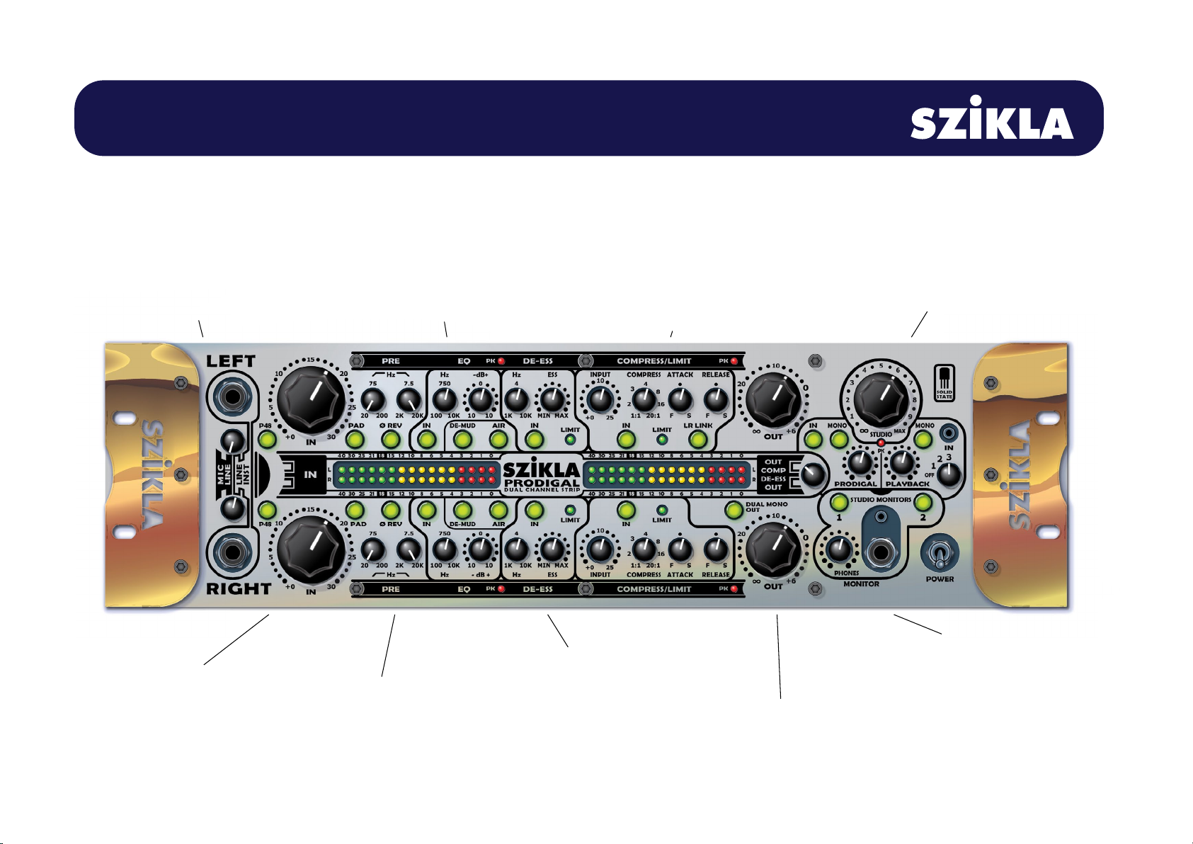
PRODIGAL Dual Analog Channel Strip & Monitor Station
www.szikla.com
Input Preamp
Processes all signals from selected inputs.
Silky smooth, mirror balanced,
low current discrete transistor design.
Includes P48 for Mic XLR, 20dB Pad,
Phase Reverse, 30dB Gain Control Pot,
Upper and Lower +0/-3dB (12dB/octave)
Bandwidth adjust.
Input Meter
Shows post-gain/pre-EQ input level.
Displays solid VU bar with
Peak Level dot above it. Peak
hold is 3 sec with 18dB/sec decay.
Units expressed as -dB Full Scale.
Switchable
Output/Compressor/De-Esser Meter
Output Meter
Shows post-fader output level in -dB Full Scale.
Displays solid VU bar with
Peak Level dot above it. Peak
hold is 3 sec with 18dB/sec decay.
-18dBFS corresponds to +4dBu at XLR output.
Compressor Meter/De-Esser Meter
Direct display of gain reduction in dB.
Displays solid bar with zero LED permanently lit.
Output Fader
Adjusts output level
of Channel Strip.
Input Selector
Rear panel XLR Mic or Line,
Balanced/Unbalanced.
Front Panel TRS Line or Instrument D.I.
Balanced/Unbalanced.
Front Jacks are also useful when you are
using the Channel Strip as an insert,
or printing tracks.
Monitor Station
Central listening control section.
Mix local audio at zero latency
with DAW playback or other source
and send all via separate master faders to
Phones and/or Studio Monitor outputs 1 & 2.
Playback input 3 is configured to receive TRS
headphone output from your smart-phone, which
may also be confugured to serve as a talk-back mic.
Headphone amp is designed to drive your phones
LOUD.
EQ
Single band, tight, responsive, and sweepable over 6.5 octaves.
+/-10dB Cut/Boost, 1 octave, Constant Q.
De-Mud
Simple and handy fixed band that targets the un-musical LF in a vocal,
instrument or live room. Low Cut -3dB at 300Hz, 1 octave wide.
Air
Enhances the edges and air around vocals, strings, etc.
Helps bring vocals forward. Fixed Band of High Boost
Flat to 9KHz, +1dB/10KHz,+10dB/20KHz.
Accurate phase up to 20KHz and no dip below the boost band.
De-Ess
Reduces sibilance in Vocals, etc.
Applies natural sounding active FET limiting to
the high frequency band. Hz control sets
the crossover point. Ess control sets the operating
threshold which is tied to and varies with a
fast-averaged sample of the full-bandwidth signal.
This helps keep the amount of De-Essing consistent
regardless of program volume and dynamics.
Attack=0.5mS Release=40mS.
Limit LED glows dynamically as limiting occurs.
Left and Right channel FETs are hand-matched.
Compress/Limit
Transparently reduces dynamic peaks in program material.
Applies ultra fast FET soft-knee limiting with faithful
harmonics and sparkling linear phase. Compress control
varies compression ratio and threshold together so
that more input signal results in more compression with
peaks maintained at around -12dBFS. Great for airy vocals, or
producing tight, level bass tracks. Loves being driven super hard.
Attack=5uS~2.5mS Release=50mS~1.3 Sec.
Limit LED glows dynamically as limiting occurs, and reaches
full illumination at the maximum gain reduction of -22dB.
Left and Right channel FETs are hand-matched
for seemless alignment of stereo image. FRONT PANEL