T.L. FAHRINGER FW-200 HPA User manual

FW-200 HPA
FLASH-BUTT WELDER
OWNER’S MANUAL
T. L. Fahringer Co.
P.O. Box 1412
Brandon, FL 33509-1412
Toll Free: 800-237-3829
Local: 813-681-2373
Web: www.fahringer.com

IMPORTANT:
PLEASE READ AND UNDERSTAND THIS
ENTIRE MANUAL BEFORE OPERATING
THIS MACHINE. PERFORMING
IMPROPER PROCEDURES MAY
VOID THE WARRANTY ON THIS
MACHINE AND COULD CAUSE SERIOUS
INJURY TO THE OPERATOR.

FW-200 HPA, Rev. 4
TABLE OF CONTENTS
Section 1: Installation
Items Required for Installation …………………………………….….
1-1
Items Required for Operation …………………………………………
1-1
Insallation Procedures ………………………………………………...
1-2
Section 2: Operating Instructions
Diagram of Welder ……………………………………………………
2-1
Explanations of Controls ……………………………………………...
2-2
General Setup ………………………………………………………..
2-5
Setup Mode ………………………………………………………
2-5
Jaw Gap Distance Indicator Calibration …………………………
2-5
Cam Positioning ………………………………………………….
2-5
Timing Calibration ……………………………………………….
2-6
Clamping Pressure Distribution Adjustment …………………….
2-6
Blade Guide Alignment, Back Edge ……………………………..
2-7
Blade Guide Alignment, Tooth Edge …………………………….
2-7
Forge Pressure Switch Calibration ……………………………….
2-8
Weld Setup ……………………………………………………………
2-9
Manual Welding Procedure …………………………………………...
2-9
Anneal Setup ………………………………………………………….
2-10
Manual Annealing Procedure …………………………………………
2-10
Obtaining New Anneal Settings ………………………………………
2-11
Automatic Welding and Annealing Procedure ………………………. 2-11
Settings Chart …………………………………………………………
2-12
Section 3: Maintenance
Care and Maintenance of Welding Jaws ……………………………...
3-1
Reconditioning Welding Jaws ………………………………………...
3-1
Periodic Maintenance …………………………………………………
3-1
Removing Clamps, Lower Jaws & Guide Rails ………………………
3-3
Installing Clamps, Lower Jaws & Guide Rails ……………………….
3-4

Section 1
INSTALLATION

FW-200 HPA, Rev. 4
1-1
ITEMS REQUIRED FOR INSTALLATION
- Screwgun with #2 phillips attachment or #2 phillips screwdriver
- #1 phillips screwdriver
- Flat blade screwdriver, medium
- Allen wrench set, 1/16” - 3/8”
- Crescent wrench
- Fork-lift or Pallet jack
- Main Power requirements (CHECK MACHINE LABELS FOR PROPER OPERATING VOLTAGE)
- 220 VAC or 440 VAC, 1
- Minimum 80-amps (recommend 100-amps) @ 220 VAC
- Minimum 40-amps (recommend 50-amps) @ 440 VAC
- Power must be supplied through a minimum 80-amp breaker and power cord of suitable size and length (See Installation
Procedures)
- 115 VAC Power, supplied via a standard extension cord, for the auto-switching outlet
- 100-psi air supply and air hose with standard female quick disconnect fitting
- Oil (30 weight or heavier)
- Water-cooling pump to accept 1/4” I.D. water-cooling hose and tank to hold at least 15 U.S. gallons of water
(i.e. LITTLE GIANT model: 2E-N pump)
- Dial or digital calipers, 4” - 6”
ITEMS REQUIRED FOR OPERATING THE FW-200 HSA
- 3/16” T-handle allen wrench at least 3” long
- Ratchet wrench with 7/16” socket
- Flat blade screwdriver, medium
- #1 phillips screwdriver
- 5/16” box wrench
- 11/32” box wrench
- 24” steel straightedge 1/16”-1/8” thick
- Allen wrench set, 1/16” - 3/8”
- SILICONE FREE Welding anti-spatter spray (Recommend: WELD AID PRODUCTS Nozzle-Kleen #2)
- Cloth rags
- Fine Grit surfacing stone, 2” wide x 6” long (Recommend: NORTON #IB6 Sharpening Stone)
- Dial or digital calipers, 4” - 6”
- Compressed air hose with nozzle

FW-200 HPA, Rev. 4
1-2
CAUTION:
ALL ELECTRICAL HOOK-UPS SHOULD BE PERFORMED BY A QUALIFIED ELECTRICAL
TECHNICIAN AND COMPLY WITH ALL OSHA REGULATIONS.
INSTALLATION PROCEDURES
1) Open the welder crate.
a) Remove the screws around the bottom of the box.
b) Remove the front panel from the crate.
c) Carefully slide the crate off toward the rear of the welder.
2) Remove the clamping footpedals from their mounted position on the pallet and place them temporarily inside the welder stand.
3) Remove the four mount bolts holding the welder to the pallet.
4) Lift the welder off the pallet with a forklift or other suitable means.
5) If desired, mount the stand feet (located in a box inside the welder stand) into the holes from which the pallet mount bolts were
removed.
6) Place the welder in the desired position on floor.
7) Power must be supplied through a minimum 80-amp breaker. Use the following guidelines to determine the size and length of the
power cord.
• At least 8 gauge at no more than 100 feet in length from breaker
• At least 6 gauge at no more than 150 feet in length from breaker
• At least 4 gauge at no more than 200 feet in length from breaker
• At least 2 gauge at no more than 250 feet in length from breaker
DANGER: ALWAYS TURN ALL POWER TO THE MACHINE OFF AT THE BREAKER BEFORE
OPENING THE LOWER CONTROL BOX. FAILURE TO DO SO MAY RESULT IN
SERIOUS INJURY OR DEATH!
8) Turn power to the machine off at the breaker. Open the door to the lower control box, located on the right side of the welder,
and install the main power cord through the hole in the back of the box. Attach the black & white L1 & L2 wires to the MAIN
POWER block at the inputs where the black power wires are already attached (the order does not matter).
9) Attach the green Ground wire to MAIN POWER block at the input where the green ground wires are already attached.
10) If desired, plug the female end of an extension cord to the male receptacle attached to the auto-switching outlet on the back of the
welder, and plug the other end of the extension cord into a standard 115 VAC powered outlet. The auto-switching outlet will then
turn on and off in sync with the welder in order to power a water cooling pump, or other device, only when the welder is turned
on.
11) Turn power to the machine on and check the voltage either with a voltmeter at the MAIN POWER block or by turning the
machine on and reading the voltage on the LINE VOLTAGE METER located on the front of the lower control box.
12) Set the LINE VOLTAGE SWITCH to the position closest to your measured power voltage.
13) Close and lock the door to the lower control box.
14) Plug an air hose onto the air fitting located at the rear of the machine and set the main regulator for between 80 and 100-psi.
15) Remove the left front cover from the machine and fill the oil cup, located under the cam, with oil. (Any oil 30 weight or heavier)
16) Check the GENERAL SETUP of the machine for any maladjustment that may have occurred during shipment; timing calibration,
blade guide alignment, jaw gap distance indicator calibration, etc. (See GENERAL SETUP)
17) Hook up one of the water-cooling hoses to a submersible water pump, the hoses are ¼” I.D., and place the pump in a water tank
(minimum 15 gallons). Run the other hose into the water tank to act as a return line.
18) Plug the water pump into the auto-switching outlet on the back of the welder, or other power source, and ensure the water cooling
system is operating.
19) Before running the welder make sure to replace all covers. NEVER WELD WITHOUT ALL COVERS IN PLACE.

Section 2
OPERATING
INSTRUCTIONS

FW-200 HPA, Rev. 4
2-1

FW-200 HPA, Rev. 4
2-2
EXPLANATIONS OF CONTROLS
B1 - WELD BUTTON
Weld Cycle Start
Button is enabled when its green light is on and both clamps are down.
In Manual or Weld Only mode the green light comes on when the welder is at weld start, and remains on during a weld cycle.
In Auto mode the green light comes on when the welder is calibrated and at weld start, and remains on during the auto cycle.
B2 - ADVANCE BUTTON
Advances the welder to the next available position; Calibrates Machine in Auto mode
Button is enabled when its yellow light is on and both clamps are up.
B3 - ANNEAL BUTTON
Anneal Cycle Start/Stop; Alarm Reset
Button is enabled when its red light is on and both clamps are down.
The red light comes on at the anneal position, and remains on during an anneal cycle.
B4 - AIR BLOW-OFF BUTTON
Manually activates the air blow-off system.
P1 - ANNEAL HEAT 1 KNOB
Adjusts the anneal heat for the Ramp Stage.
Heat Range = 100 - 999
100 = 0 volts
999 = Max. Weld Voltage as set by the WELD VOLTAGE SWITCH
P2 - ANNEAL HEAT 2 KNOB
Adjusts the anneal heat for the Soak Stage.
Heat Range = 100 - 999
100 = 0 volts
999 = Max. Weld Voltage as set by the WELD VOLTAGE SWITCH
T1 - ANNEAL TIMER 1
Sets the amount of time Anneal Heat 1 is applied for the Ramp Stage.
Set the time by pressing the button below the display that corresponds with the position of the number you want to change.
T2 - ANNEAL TIMER 2
Sets the amount of time Anneal Heat 2 is applied for the Soak Stage.
Set the time by pressing the button below the display that corresponds with the position of the number you want to change.
T3 - DELAY TIME
Sets the amount of time cool down time before the air blow off activates after a blade has been welded in the auto mode.
Set the time by pressing the button below the display that corresponds with the position of the number you want to change.
S1 - WELD VOLTAGE SWITCH
Sets the maximum voltage for welding and/or annealing.
0 = Off
1 = 3.0 volts
2 = 3.6 volts
3 = 4.2 volts
4 = 4.8 volts
5 = 5.4 volts
6 = 6.0 volts
S2 - LINE VOLTAGE SWITCH
Compensates for high or low power voltage.
Select the setting that is closest to, but not below, the incoming voltage level powering the machine.

FW-200 HPA, Rev. 4
2-3
S3 - MAIN SWITCH
Turns the main power to the machine ON or OFF.
S4 - MODE SWITCH
Sets the operating mode of the welder
AUTO - Welds, then automatically re-centers the blade and moves to the anneal position, anneals, and moves back to weld start.
Advancing is disabled unless the welder is not calibrated or is not at weld start.
When enabled, advancing moves to weld start, then becomes disabled.
MANUAL - Welding and annealing are done manually as separate cycles.
Advancing stops at all positions: 1) Weld Start, 2) Weld Stop, 3) Anneal
WELD ONLY - Only welding can be done in this mode.
Advancing bypasses the anneal position and stops only at weld start and weld stop.
S5 - FLASHING SPEED SWITCH
Sets the rate at which the blade-ends are fed together during welding. 1is Slowest; 6is Fastest; 0is Off
S6 - CLAMPING MODE SWITCH
SINGLE - Each footpedal activates its corresponding clamp separately
DUAL - Either footpedal will activate both clamps simultaneously
M1 - WELD VOLTAGE METER
Indicates the output voltage level at the jaws.
M2 - LINE VOLTAGE METER
Indicates the voltage level powering the machine.
L1 - POWER LIGHT
Indicates the main power is turned ON.
R1 - FORGE PRESSURE REGULATOR
Adjusts the amount of pressure applied to the sliding carriage assembly during forging.
CW - Adjusts the pressure higher
CCW - Adjusts the pressure lower
R2 - FOLLOWING PRESSURE REGULATOR
Adjusts the amount of pressure applied to the sliding carriage assembly while advancing or during flashing.
R3 - CLAMPING PRESSURE REGULATOR
Adjusts the clamping pressure.
G1 - FORGE PRESSURE GAUGE
Indicates the forging pressure set by the Forge Pressure Regulator.
G2 - FOLLOWING PRESSURE GAUGE
Indicates the following pressure set by the Following Pressure Regulator.
G3 - CLAMPING PRESSURE GAUGE
Indicates the clamping pressure set by the Clamping Pressure Regulator.
CLAMPING FOOTPEDALS
Toggle clamps Up and DOWN.
JAW GAP ADJUSTMENT SCREW
Adjusts the distance between the jaws.
CW - Adjusts the jaw gap larger
CCW - Adjusts the jaw gap smaller
JAW GAP DISTANCE INDICATOR
Indicates the current distance between the jaws.

FW-200 HPA, Rev. 4
2-4
TIMING ADJUSTMENT KNOB
Adjusts the moment of weld current cut-off.
CW - Adjusts weld current cut-off sooner
CCW - Adjusts weld current cut-off later
TIMING POSITION INDICATOR
Indicates the current position of weld current cut-off.
JAWS
Clamp the blade to be welded or annealed between the upper and lower jaws.
BLADE GUIDES
Guides to align the blade horizontally.
Guides to align either the back edge or tooth edge of the blade are available.
Positions 1-4 on the tooth edge guides are for smaller to larger tooth sizes, respectively.

FW-200 HPA, Rev. 4
2-5
GENERAL SETUP
This section describes how to perform the general setup of the welder. These procedures have already been performed at the
factory prior to shipment. However, during shipment these settings are often knocked out of adjustment; therefore, it is recommended
that, once installed, the machine be setup again prior to use.
SETUP MODE
It is necessary to enter into a special “SETUP” mode for some operations. The following describes the procedure for entering
setup, and how to operate the machine while in setup.
TO ENTER SETUP:
1) Select MANUAL on the mode switch.
2) With both clamps in the UP position, press the ADVANCE BUTTON until the machine arrives at the ANNEAL
position, signified by the red light. (At this point the yellow and red lights should both be on.)
3) Press and hold the WELD BUTTON, then press the ADVANCE BUTTON while holding the weld button. All three
lights, green, yellow and red, should come on. This indicates the machine is in setup mode.
TO EXIT SETUP:
Just press the ANNEAL BUTTON at any time.
WHILE IN SETUP:
• The WELD BUTTON acts as a toggle ON/OFF for the cam motor.
• The ADVANCE BUTTON acts as a jog for the cam motor.
• The cam motor speed is set at the rapid feed rate when the mode switch is set to WELD ONLY.
• The cam motor speed is set by the FLASHING SPEED SWITCH when the mode switch is set to NORMAL.
• Clamping is disabled.
JAW GAP DISTANCE INDICATOR CALIBRATION
The jaw gap indicator should be checked periodically, every time the lower jaws are removed, or if weld quality seems to decline.
An accurate jaw gap is essential to good weld quality.
1) Measure the gap between the lower jaws with a pair of calipers.
2) Adjust the jaw gap distance indicator adjustment screw until the indicator reads the same as the current jaw gap.
CAM POSITIONING
Positioning of the cam relative to its four position points is adjusted via the three positioning discs attached to the camshaft behind
the front plate of the welder. This procedure only needs to be performed if the cam does not stop at its correct positions.
THIS PROCEDURE SHOULD ONLY BE PERFORMED WITH THE ASSISTANCE OF AN AUTHORIZED
T. L. FAHRINGER CO. SERVICE TECHNICIAN!
FW-200 HPA, Rev. 4
2-6
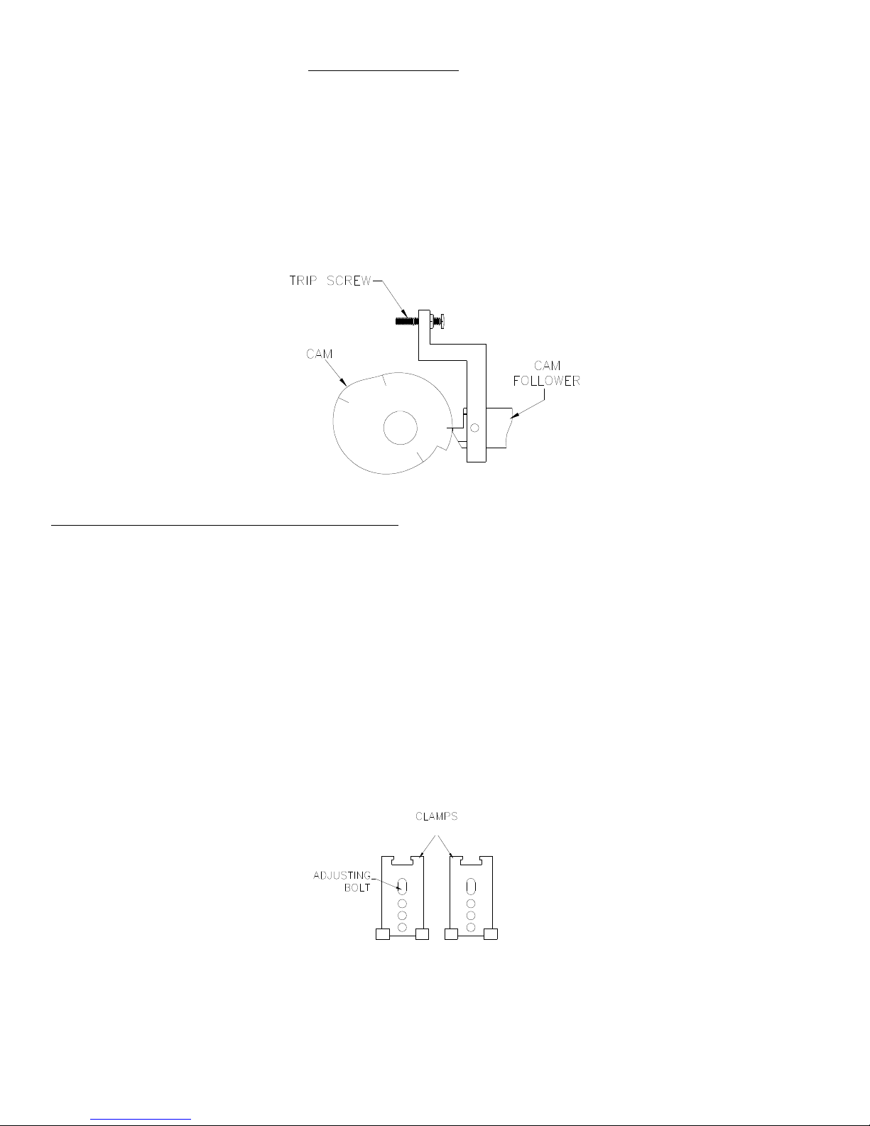
TIMING CALIBRATION
The timing calibration should be checked periodically to ensure accuracy.
1) Remove the left cover from the front of the machine.
2) Enter into the SETUP mode.
3) Set the timing for around 0.100”.
4) JOG the motor until the cam follower is lined up with the cam’s timing mark (See Diagram).
5) Turn the timing adjustment knob CW until a ½-second beep is heard. The beep should occur just when the timing position
indicator needle passes -0.020”.
6) Adjust the trip position, if necessary, by turning the trip screw. CW causes the timing to trip sooner; CCW causes the timing
to trip later.
7) Recheck the calibration by turning the timing adjustment knob CCW at least 0.010”, more if necessary, to reset the switch,
then repeat from step 5.
CLAMPING PRESSURE DISTRIBUTION ADJUSTMENT
For reliable weld results the clamping pressure must be uniformly distributed across the blade. To check the clamping pressure a
carbon paper impression can be utilized. Insert a length of blade of the desired size into the welder. Place a piece of white paper on top
of the blade, then a piece of carbon paper on top of the white paper with the carbon side down, and clamp in place. Unclamp the
clamps and look at the impressions of the jaws on the white paper. They should be an even color from front to back. This denotes even
clamping pressure. If the impressions are not even, the points of darkest color and greatest width indicate the areas of heavier
clamping pressure. Follow the procedure below to adjust how the clamping pressure is distributed.
PLEASE NOTE: It is normal for the upper jaw impressions of each clamp to fade toward the middle. This happens because the
upper jaws sit at angle in the clamps to force the clamping pressure to the outside edges.
1) Unclamp both clamps.
2) Turn the Adjusting Bolt (see diagram) in the desired direction. CW adjusts the pressure toward the back. CCW adjusts the
pressure toward the front. (Adjustments in 1/32-1/16 turn increments are recommended. Adjusting too far in or out could
cause the clamp to stick or the slide to crack.)
3) Repeat step 2, if necessary, for the remaining clamp.
4) Recheck the clamping pressure with carbon paper.
5) Repeat the procedure if necessary.
Once the clamping pressure is set properly using carbon paper, the clamps can be adjusted for different blade sizes by looking at the
anneal heat pattern produced during annealing. If the anneal pattern is uneven, adjust both clamps evenly to compensate. Be sure to
adjust both clamps by the same amount. If the clamps get out of sync they will need to be reset with a carbon paper check.

FW-200 HPA, Rev. 4
2-7
BLADE GUIDE ALIGNMENT
There are two types of alignment systems available for the FW-200 welder, Back Edge and Tooth Edge. The Tooth Edge system
can be obstructive when loading and unloading blades and is more difficult to calibrate than the Back Edge system, but once calibrated
the guides are simply rotated from one setting to the next for different width blades. The Back Edge system does not obstruct loading
and unloading and is much easier to re-calibrate, but requires re-calibrating whenever changing blade widths.
NOTE: All blade-stock has a curve in the back edge known as “camber”. If the camber is too severe, using Back Edge guides that are
setup straight may cause blade misalignment. However, this is not a problem for most material.
BACK EDGE GUIDE CALIBRATION
1) Mount the calibration guides to the front of the carriages, making sure the mating surfaces are clean and smooth, and rotate
them to a setting sufficient for the desired blade’s tooth size. (Note: Make sure the front of the lower jaws do not interfere
with the calibration guides as this will cause them to not sit flush against the front of the carriage.)
2) Loosen all four guides and slide them all the way to the back.
3) Insert a blade of the desired size into the jaws, pull it against the calibration guides, and clamp it in place.
4) Slide the two inside guides against the back of the blade and tighten them in place.
5) Remove the calibration guides and the blade from the machine and set them aside.
6) Insert a 1/16”-1/8” thick x 24” long steel straightedge into the jaws, push it against the inside guides, and clamp it in place.
7) Pull the outside guides against the straightedge and tighten them in place.
8) Unclamp and remove the straightedge from the machine.
TOOTH EDGE GUIDE CALIBRATION
1) Mount the inner guides to the front of the carriages, making sure the mating surfaces are clean and smooth, and rotate them to
setting #4. (Note: Make sure the front of the lower jaws do not interfere with the blade guides as this will cause them to not
sit flush against the front of the carriage.)
2) Rotate the outer guides to setting #4.
3) Load a 1/16”-1/8” thick x 24” long steel straight-edge into the jaws, pull it against the INNER guides mounted to the front of
the carriages, and clamp it in place.
4) The straightedge should be touching all four guides, and be able to be raised and lowered without hanging on the top of the
outer guides. (Proceed to step 10 if the outer guides are aligned.)
5) Loosen the mount screw on the bottom of the guide mount to be adjusted.
6) Slide the guide mount so that the blade guide is touching the straightedge.
7) Tighten the mount screw and recheck the alignment of the blade guide as described in step 4.
8) Repeat steps 5-7, if necessary, until alignment is achieved.
9) Repeat steps 5-8, if necessary, for the remaining outer guide.
10) Unclamp the straightedge, remove the inner guides from the carriages and mount them to the inner guide mounts, then rotate
them to setting #4.
11) Load the straightedge into the jaws, pull it against the OUTER guides, and clamp it in place.
12) The straightedge should be touching all four guides. (Proceed to step 15 if the inner guides are aligned.)
13) Perform steps 5-8.
14) Repeat step 13, if necessary, for the remaining inner guide.
15) Unclamp and remove the straightedge from the jaws.

FW-200 HPA, Rev. 4
2-8
FORGE PRESSURE SWITCH CALIBRATION
The forge pressure switch calibration should be checked periodically to ensure accuracy. The forge pressure is activated by the #4
sensor and disc attached to the cam shaft, and are accessed by removing machine’s the top cover.
1) Remove the left cover from the front of the machine.
2) Enter into the SETUP mode.
3) Set the timing for around 0.150”.
4) JOG the cam from weld start until the cam follower is lined up with the cam’s timing mark.
a) If the machine beeps during step 4 then the forge pressure switch calibration is very early. Proceed to step 7.
b) Otherwise proceed to step 5.
5) JOG the cam SLOWLY, by quickly tapping the ADVANCE button, from the timing mark toward the drop-off until the
machine beeps, then stop immediately.
6) The cam follower should be lined up with the cam about 1/16” above the drop-off right when the machine beeps.
(See Cam Diagram)
a) If the forge pressure is calibrated, proceed to step 12.
b) Otherwise proceed to step 7.
7) Remove the top cover from the machine.
8) Adjust the trip position, if necessary, by loosening the set screw of and turning the #4 disc.
a) CCW (in direction of cam rotation) causes the forge pressure to trip sooner.
b) CW (against direction of cam rotation) causes the forge pressure to trip later.
9) Recheck the calibration from step 4.
10) Make sure the disc’s set screw is tight. If it is not, tighten it, and then recheck the calibration from step 4.
11) Replace the top cover on the machine.
12) Replace the left cover on the front of machine.
13) Exit out of SETUP mode.
14) The forge pressure switch is now calibrated.

FW-200 HPA, Rev. 4
2-9
WELD SETUP
These procedures are performed whenever there is a change of the blade size and/or type being welded. Some suggested settings are
listed in the settings chart of this manual (See “SETTINGS”). NOTE: The suggested settings are only baseline settings and may need to be
changed to meet the user's specific requirements and/or shop conditions.
SET JAW GAP
1) Advance to the WELD START position, indicated by the green light.
2) Turn the JAW GAP ADJUSTMENT SCREW in the desired direction.
3) If in Auto mode a ½-second beep will be heard to signify the machine needs to be recalibrated; Press the ADVANCE BUTTON to
recalibrate the machine.
CAUTION: NEVER TURN THE JAW GAP ADJUSTMENT SCREW WHILE THE CAM IS TURNING!
SET TIMING
Turn the TIMING ADJUSTMENT KNOB in the desired direction.
SELECT WELD VOLTAGE
Set the WELD VOLTAGE SWITCH to a position 1-6.
SET FORGE PRESSURE
Turn the FORGE PRESSURE REGULATOR to the desired setting.
SET FOLLOWING PRESSURE
Turn the FOLLOWING PRESSURE REGULATOR to the desired setting.
SELECT FLASHING SPEED
Set the FLASHING SPEED SWITCH to a position 1-6.
SET BLADE GUIDES
Adjust the BLADE GUIDES to accommodate the blade's tooth size.
ADJUST CLAMPING PRESSURE DISTRIBUTION
Check the clamping pressure distribution and adjust if necessary.
MANUAL WELDING PROCEDURE
1) Select MANUAL or WELD ONLY mode.
2) Setup for the desired blade size.
(See “WELD SETUP”)
3) Select the desired clamping mode.
4) Advance to the weld start position.
a) Both clamps must be UP.
b) Press the ADVANCE BUTTON until the green weld light comes on.
5) Load the blade.
a) With both clamps UP, insert the blade-ends into the jaws with the teeth facing the operator.
b) The blade should be against all four blade guides.
c) Butt the blade-ends together leaving about a 0.010” - 0.020” gap between them and center the blade joint between the jaws.
d) Clamp the blade-ends in place making sure they are not overlapping, and the blade is against all four guides.
6) Press the WELD BUTTON to start the weld cycle.
a) Both clamps must be DOWN.
7) Unclamp & remove the blade when the weld cycle is finished.
a) The weld cycle is finished when the green weld light goes out and the yellow advance light comes on.

FW-200 HPA, Rev. 4
2-
10
ANNEAL SETUP
SET JAW GAP
This is set at the Weld Start position and is the same setting used for welding the blade. (See WELD SETUP)
SELECT WELD VOLTAGE SETTING
Use the same setting used for welding the blade. (See WELD SETUP)
SET ANNEAL TIME 1
Type the desired Ramp Up time for the anneal cycle into ANNEAL TIMER 1.
SET ANNEAL HEAT 1
Turn the ANNEAL HEAT 1 Knob to the desired Ramp Up setting.
SET ANNEAL TIME 2
Type the desired Soak time for the anneal cycle into ANNEAL TIMER 2.
SET ANNEAL HEAT 2
Turn the ANNEAL HEAT 2 Knob to the desired Soak setting.
SET BLADE GUIDES
Adjust the BLADE GUIDES to accommodate the blade's tooth size.
ADJUST CLAMPING PRESSURE DISTRIBUTION
Check the clamping pressure distribution and adjust if necessary.
MANUAL ANNEALING PROCEDURE
1) Set the mode switch to MANUAL.
2) Setup for the desired blade size.
(See “ANNEAL SETUP”)
3) Advance to the ANNEAL position.
a) Both clamps must be UP.
b) Press the ADVANCE BUTTON until the red anneal light comes on.
4) Load a welded blade.
a) With both clamps UP, insert the blade with the weld-burr between the jaws and the teeth facing the operator.
b) Position the blade against all four guides.
c) Center the weld-burr between the jaws and clamp the blade in place.
5) Press the ANNEAL BUTTON to start the anneal cycle.
a) Both clamps must be DOWN.
6) Unclamp & remove the blade when the anneal cycle is finished.
a) The anneal cycle is finished when ANNEAL TIMER 2 reaches zero and the yellow advance light comes on.
NOTE: The anneal cycle can be stopped early by pressing the ANNEAL BUTTON while the anneal cycle is running.

FW-200 HPA, Rev. 4
2-
11
OBTAINING NEW ANNEAL SETTINGS
1) Set ANNEAL TIME 1 for 0.1 seconds
2) Set ANNEAL TIME 2 for 900.0 seconds
3) Set both ANNEAL HEAT 1 & 2 for 200 – 250
4) Load a blade of the desired size and initiate an anneal cycle
5) Adjust ANNEAL HEAT 2 until the desired temperature is reached and holds steady
6) Set ANNEAL TIME 2 for the desired soak time (probably around 3 – 5 seconds)
7) Set ANNEAL TIME 1 for the desired ramp time (usually around 5 seconds)
8) Set ANNEAL HEAT 1 around 50-100 points higher than ANNEAL HEAT 2
9) Load a fresh blade and initiate another anneal cycle
10) If needed, adjust the settings accordingly and repeat from Step 9 until the desired ramp and soak effect is achieved
AUTOMATIC WELDING & ANNEALING PROCEDURE
1) Select AUTO mode.
2) Setup for welding and annealing the desired blade size.
(See “WELD SETUP” & “ANNEAL SETUP”)
3) Set the ANNEAL DELAY time.
Type the time for the duration of the auto anneal delay into the ANNEAL DELAY TIMER.
4) Calibrate the machine, if necessary.
a) The welder is out of calibration if the green light does not come on and a ½-second beep sounds at the weld start position.
b) With both clamps UP, press the ADVANCE BUTTON to re-calibrate.
5) Select the desired clamping mode.
6) Adjust air blow-off hoses
Adjust the air blow-off hoses so they are aimed at the center of the blade where it meets the outer jaws.
7) Advance to the weld start position.
a) Both clamps must be UP.
b) Press the ADVANCE BUTTON until the green weld light comes on.
8) Load the blade.
a) With both clamps UP, insert the blade-ends into the jaws with the teeth facing the operator.
b) The blade should be against all four blade guides.
c) Butt the blade-ends together leaving about a 0.010” - 0.020” gap between them and center the blade joint between the jaws.
d) Clamp the blade-ends in place making sure they are not overlapping, and the blade is against all four guides.
9) Press the WELD BUTTON to start the automatic weld cycle.
a) Both clamps must be DOWN.
10) Unclamp and remove the blade when the cycle is finished.
a) Automatic cycle is finished when both clamps release and the machine moves back to the weld start position after annealing.

FW-200 HPA SETTINGS
BLADE
SIZE/TYPE
JAW GAP
(in)
TIMING
(in)
WELD
VOLTAGE
FLASHING
SPEED
FORGE
PRESSURE
(psi)
FOLLOW
PRESSURE
(psi)
DELAY TIME
(sec)
ANNEAL
HEAT 1
ANNEAL
TIME 1
ANNEAL
HEAT 2
ANNEAL
TIME 2
.250 - .300 .000 - .002 1 - 2 5 - 6 4 - 6 2 - 3 0+ 3 - 6 2 - 10
.280 - .310 .002 - .010 1 - 2 5 - 6 4 - 8 3 - 5 1+ 3 - 6 3 - 10
.300 - .325 .005 - .010 2 - 3 4 - 6 6 - 10 3 - 5 2+ 3 - 6 3 - 10
.325 - .350 .005 - .015 2 - 3 4 - 6 15 - 25 4 - 6 3+ 4 - 8 5 - 10
.350 - .400 .010 - .040 3 - 4 4 - 6 25 - 40 4 - 6 4+ 4 - 10 5 - 10
.400 - .475 .020 - .050 4 - 5 4 - 6 35 - 45 5 - 8 5+ 5 - 10 5 - 20
.475 - .550 .030 - .075 4 - 6 3 - 5 35 - 55 7 - 10 7+ 5 - 15 10 - 25
.500 - .575 .035 - .125 5 - 6 3 - 5 40 - 60 7 - 10 10+ 5 - 15 10 - 30
1"
1-1/4"
1-1/2"
2"
1/4"
3/8"
1/2"
3/4"
WELD SETTINGS RAMP STAGE SOAK STAGE
ANNEAL SETTINGS

FW-200 HPA SETTINGS
BLADE
SIZE/TYPE
JAW GAP
(in)
TIMING
(in)
WELD
VOLTAGE
FLASHING
SPEED
FORGE
PRESSURE
(psi)
FOLLOW
PRESSURE
(psi)
DELAY TIME
(sec)
ANNEAL
HEAT 1
ANNEAL
TIME 1
ANNEAL
HEAT 2
ANNEAL
TIME 2
WELD SETTINGS RAMP STAGE SOAK STAGE
ANNEAL SETTINGS
Table of contents


