T-Link T-Link-EV5273 User manual

T-Link-EV5273/5276/5250
User Manual
Rev 0.90
tenx reserves the right to change or discontinue the manual and online documentation to this product herein to improve
reliability, function or design without further notice. tenx does not assume any liability arising out of the application or use of
any product or circuit described herein; neither does it convey any license under its patent rights nor the rights of others. tenx
products are not designed, intended, or authorized for use in life support appliances, devices, or systems. If Buyer purchases or
uses tenx products for any such unintended or unauthorized application, Buyer shall indemnify and hold tenx and its officers,
employees, subsidiaries, affiliates and distributors harmless against all claims, cost, damages, and expenses, and reasonable
attorney fees arising out of, directly or indirectly, any claim of personal injury or death associated with such unintended or
unauthorized use even if such claim alleges that tenx was negligent regarding the design or manufacture of the part.
T-Link-EV5273/5276/5250 User Manual
UM-T-Link-EV5273_5276_5250_E
2
Rev 0.90, 2016/11/07
AMENDMENT HISTORY
Version
Date
Description
V0.90
Nov, 2016
New release.

T-Link-EV5273/5276/5250 User Manual
UM-T-Link-EV5273_5276_5250_E
3
Rev 0.90, 2016/11/07
CONTENTS
AMENDMENT HISTORY.........................................................................................................2
1. Outline....................................................................................................................................4
2. Introduction...........................................................................................................................4
3. T-Link-EV5273/5276/5250 Hardware Description............................................................5
4. How to start using T-Link-EV5273/5276/5250 simulation................................................7
5. How to use four wires to program or simulate by T-Link Board...................................18
6. How to update tenx IDE & T-Link F/W...........................................................................19
7. How to use Touch Key Application...................................................................................21
8. How to use LCD Application .............................................................................................25
9. Q & A ...................................................................................................................................27
T-Link-EV5273/5276/5250 User Manual
UM-T-Link-EV5273_5276_5250_E
4
Rev 0.90, 2016/11/07
1. Outline
Tenx (tenx technology) F51 & L51 Series single-chip is compatible with 8051, the user can use Keil
uVision series of software as a development environment, this article will introduce the software and
hardware configuration in Keil C.
2. Introduction
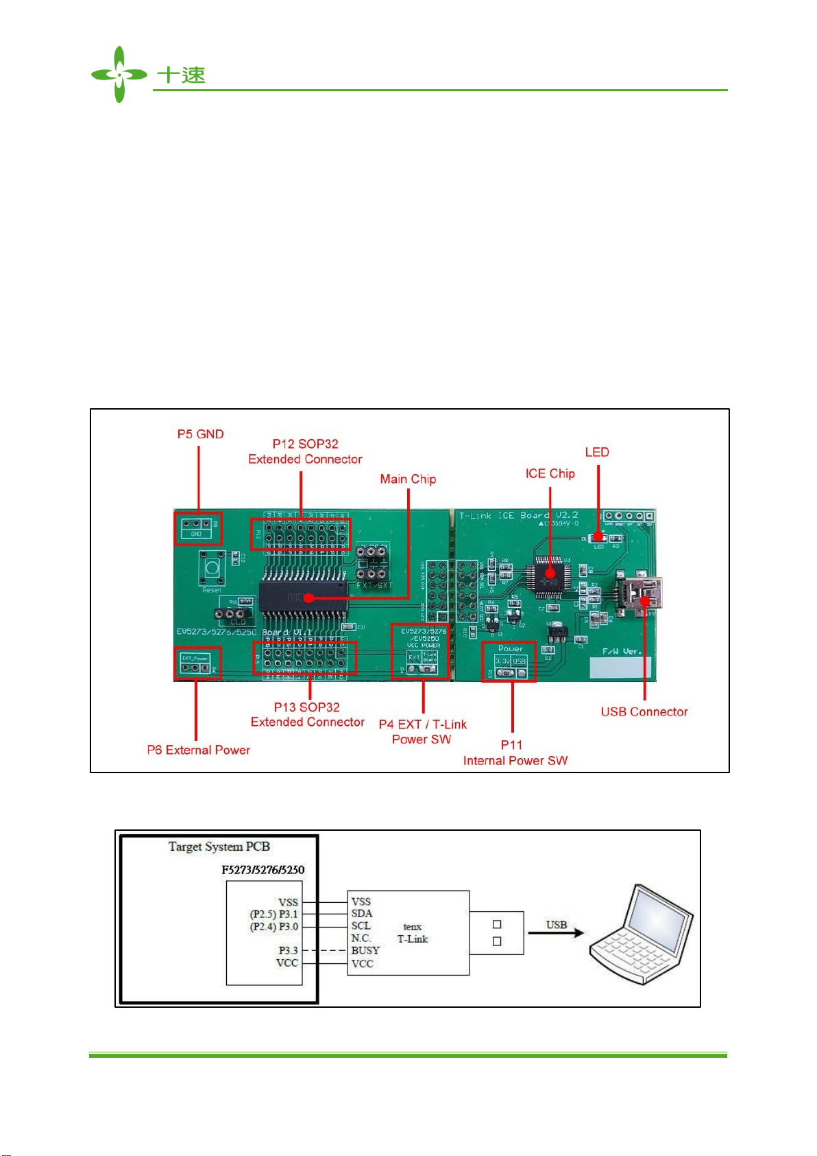
Figure 2-1 is T-Link-EV5273/5276/5250 development board, the left portion is called
EV5273/5276/5250 Board and the right portion is called T-Link ICE Board to connect PC to use, the
user can simulate TM52F5273/5276/5250 through this development board, please refer to
TM52F5273/5276/5250 datasheet in detail.
Figure 2-1. T-Link-EV5273/5276/5250 Board

T-Link-EV5273/5276/5250 User Manual
UM-T-Link-EV5273_5276_5250_E
5
Rev 0.90, 2016/11/07
3. T-Link-EV5273/5276/5250 Hardware Description
3.1 Power Setting
P6: Connect to external power (EV5273/5276/5250 Board)
P4: Internal or external power source selection (EV5273/5276/5250 Board)
P11: Internal power selection (T-Link Board)
MCU Power
P11
P6
P4
External Power
USB or 3.3V
EXT_Power
EXT
Internal Power
USB or 3.3V
X
T-Link Board
3.2 USB Connecter
P3: Mini USB connector to PC (T-Link Board)
3.3 Reset Button
Reset: Reset Button (EV5273/5276/5250 Board)
3.4 External Power Connecter
P6: External VCC connecter (EV5273/5276/5250 Board)
P5: External GND connecter (EV5273/5276/5250 Board)
3.5 MCU External Frequency-FXT/SXT
X1: crystal FXT (1~10M) /SXT(32.768K) (EV5273/5276/5250 Board)
C9: matching capacitor (EV5273/5276/5250 Board)
C10: matching capacitor (EV5273/5276/5250 Board)

T-Link-EV5273/5276/5250 User Manual
UM-T-Link-EV5273_5276_5250_E
6
Rev 0.90, 2016/11/07
3.6 PIN Assignment & Description
EV5273/5276/5250 Board contains TM52F5273/5276 main chip, packaged is SOP 32-pin
(TM52F5273/76) ; SOP 20-pin (TM52F5250) as shown below table for the pin assignment instructions.
TM52F5273/76 SOP 32-pin:
Pin Number
Pin Name
Pin Number
Pin Name
1
VSS
17
TK14/P2.4
2
XI/P2.0
18
TK15/P2.5
3
XO/P2.1
19
TK11/SEG6/SCK/P3.6
4
VPP/RSTn/INT2/P3.7
20
TK10/SEG7/MISO/P1.7
5
COM3/P0.0
21
TK9/SEG8/P1.6
6
COM2/P0.1
22
CLD/SEG9/AD9/P1.5
7
COM1/P0.2
23
TK8/SEG10/AD8/CKO/P1.4
8
COM0/P0.3
24
TK3/SEG11/AD7/PWM1A/P1.3
9
SEG0/COM4/P0.4
25
TK2/SEG12/AD6/PWM0A/P1.2
10
SEG1/COM5/P0.5
26
TK1/SEG13/AD5/T2EX/P1.1
11
SEG2/COM6/P0.6
27
TK0/SEG14/AD4/T2/P1.0
12
SEG3/COM7/P0.7
28
TK7/SEG15/AD3/RXD/P3.0
13
TK13/T0O/
SS
/SEG4/T0/ P3.4
29
TK6/SEG16/AD2/TXD/P3.1
14
TK12/MOSI/SEG5/T1/ P3.5
30
TK5/SEG17/AD1/INT0/P3.2
15
PWM0B/SEG18/P2.2
31
TK4/AD0/INT1/P3.3
16
PWM1B/SEG19/P2.3
32
VCC
TM52F5250 SOP 20-pin:
Pin Number
Pin Name
Pin Number
Pin Name
1
VSS
11
AD8/CKO/P1.4
2
XI/P2.0
12
AD7/PWM1/P1.3
3
XO/P2.1
13
AD6/PWM0/P1.2
4
VPP/RSTn/INT2/P3.7
14
AD5/T2EX/P1.1
5
T0O/T0/ P3.4
15
AD4/T2O/T2/P1.0
6
T1/ P3.5
16
AD3/RXD/P3.0
7
P3.6
17
AD2/TXD/P3.1
8
P1.7
18
AD1/INT0/P3.2
9
P1.6
19
AD0/INT1/P3.3
10
AD9/P1.5
20
VCC

T-Link-EV5273/5276/5250 User Manual
UM-T-Link-EV5273_5276_5250_E
7
Rev 0.90, 2016/11/07
4. How to start using T-Link-EV5273/5276/5250 simulation
First, Install the tenx TM52Dll IDE file to follow steps to complete the installation, the IDE & Keil C
version must be installed in the same path, the default path is C: \Keil:
4.1 Select Keil C version, click “Next>”

T-Link-EV5273/5276/5250 User Manual
UM-T-Link-EV5273_5276_5250_E
8
Rev 0.90, 2016/11/07
4.2 And then click “Next>”
4.3 The default path is C: \Keil, click “Next>”

T-Link-EV5273/5276/5250 User Manual
UM-T-Link-EV5273_5276_5250_E
9
Rev 0.90, 2016/11/07
4.4 Click “Install”
4.5 Click “Finish”to complete the installation
T-Link-EV5273/5276/5250 User Manual
UM-T-Link-EV5273_5276_5250_E
10
Rev 0.90, 2016/11/07
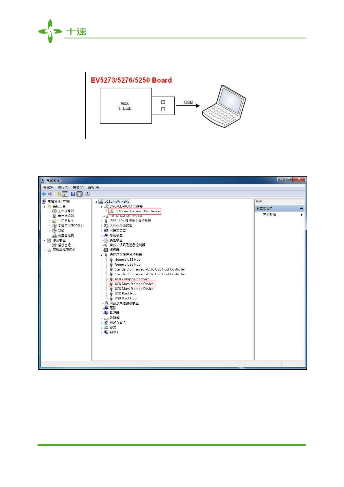
4.6 Connect T-Link-EV5273/5276/5250 Board of USB (mini type) connector to PC
4.7 Confirm Device Manger

T-Link-EV5273/5276/5250 User Manual
UM-T-Link-EV5273_5276_5250_E
11
Rev 0.90, 2016/11/07
4.8 Open the KEIL CClick the Project menu and select New Project windowFill in the project name
and click Save ProjectCopy tenx 8051 Startup Code or not?

T-Link-EV5273/5276/5250 User Manual
UM-T-Link-EV5273_5276_5250_E
12
Rev 0.90, 2016/11/07
4.9 CPU Data Base selection dialog box will be show upSelect the tenx F8051 Devices and click on
OK buttonSelect a CPU model (for EV Board model), refer to Note (1) and the right window
shows some of the parameters of this single chip model.
Note (1): TM52F5273/5276/5250 (For EV Board model)
Chip Model
EV Board Model
TM52F5273/5276
EV5273/5276/5250
TM52F5250

T-Link-EV5273/5276/5250 User Manual
UM-T-Link-EV5273_5276_5250_E
13
Rev 0.90, 2016/11/07
4.10 Option for Target dialog box settings: Click the “Option for Target”button in the main menu, the
project file is created must also be relevant to the project file settings as shown below.
4.11 Output dialog box settings: To confirm “Create HEX File”option is checked, as shown below.
T-Link-EV5273/5276/5250 User Manual
UM-T-Link-EV5273_5276_5250_E
14
Rev 0.90, 2016/11/07
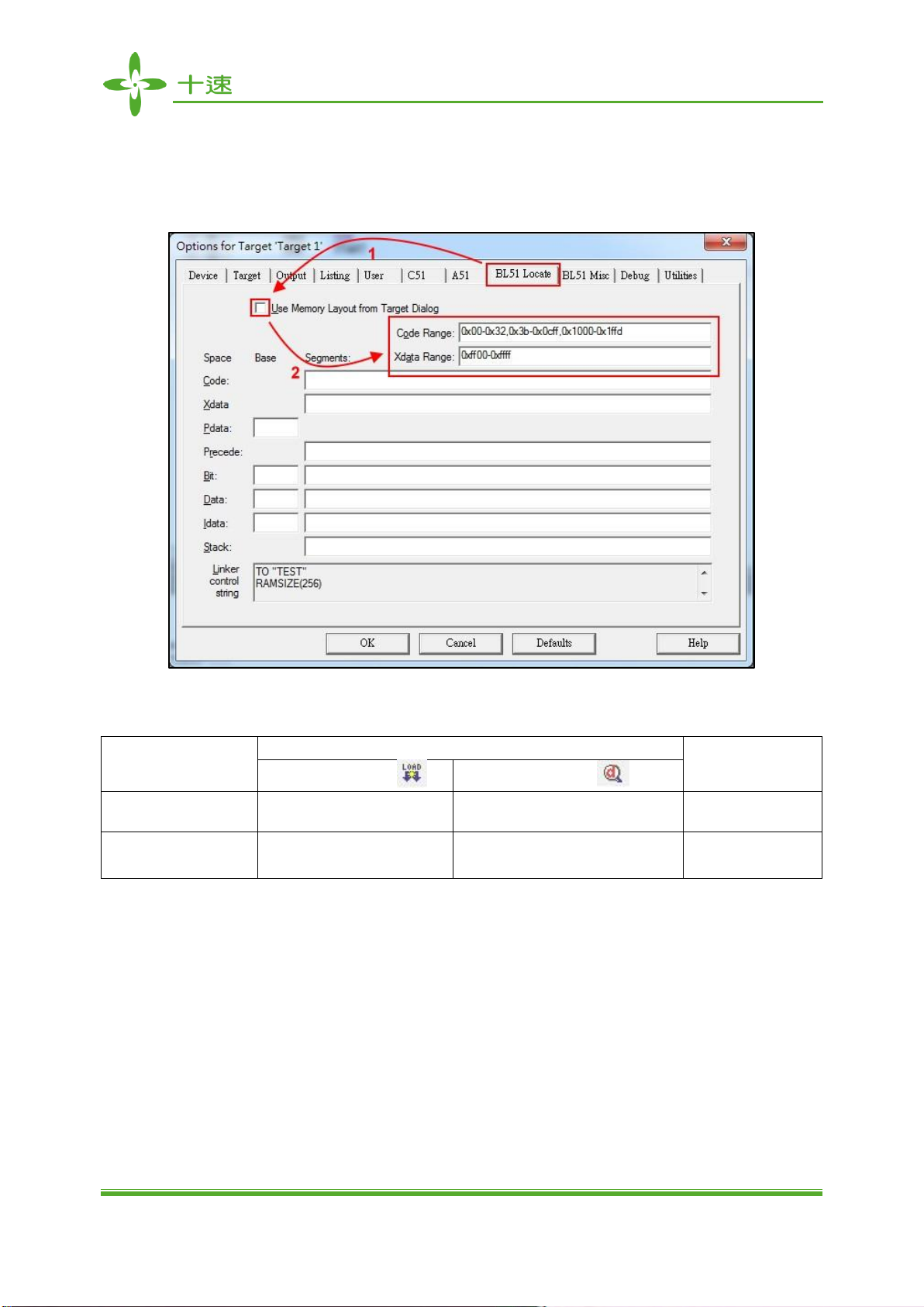
4.12 BL51 Locate dialog box settings: Unchecked “Use Memory Layout from Target Dialog” in BL51
Locate option and fill in Code & Xdata Range (Note: The chip code available range has divided
into download mode and debug mode, please refer to Note (2) )
Note (2): TM52F5273/5276/5250 (EV5273/5276/5250) Code Range area (Program ROM)
Chip Model
Code Range
XRAM Range
Download Mode
Debug Mode
TM52F5273/5276
(EV5273/5276/5250)
0x00-0x32, 0x3b-0x3ffb
0x00-0x32, 0x3b-0x1cff,
0x2000-0x3ffb
0xfe00-0xffff
TM52F5250
(EV5273/5276/5250)
0x00-0x32, 0x3b-0xffb
X
X
T-Link-EV5273/5276/5250 User Manual
UM-T-Link-EV5273_5276_5250_E
15
Rev 0.90, 2016/11/07
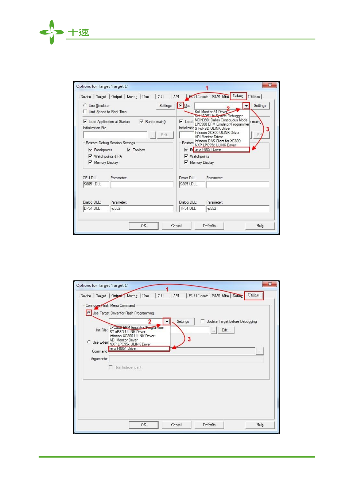
4.13 Debug dialog box settings: Click on “Use: ”option, and then select “tenx F8051 Driver”as shown
below.
4.14 Utilities dialog box settings: Click on “Use Target Driver for Flash Programming”option and
select “tenx F8051 Driver”as shown below.

T-Link-EV5273/5276/5250 User Manual
UM-T-Link-EV5273_5276_5250_E
16
Rev 0.90, 2016/11/07
4.15 Click on “settings”button and the “Flash Download Setup”window will be show up, check the
“Download Function”desired option as shown below.
4.16 Click on “Option”button, and the “Smart Option”will be show up, about the option configuration,
please refer to TM52F5273/5273/5250 datasheet.

T-Link-EV5273/5276/5250 User Manual
UM-T-Link-EV5273_5276_5250_E
17
Rev 0.90, 2016/11/07
4.17 Click on “OK”to return to “Flash Download Setup”window, and then click on “OK”to return to
“Utilities”window, this all new project configuration is complete and click on “OK”to exit the
“Option for Target”window, the user can start programming now. (Note: To change chip model,
user needs to confirm “Code Range”and “Option”settings, the “Open Project”will save the
settings and the “New Project” will be default settings in the “Option” dialog box)

T-Link-EV5273/5276/5250 User Manual
UM-T-Link-EV5273_5276_5250_E
18
Rev 0.90, 2016/11/07
5. How to use four wires to program or simulate by T-Link Board
The T-Link ICE Board can use four wires (VCC, VSS, P3.0/P2.4, P3.1/P2.5) or five wires (VCC, VSS,
P3.0/P2.4, P3.1/P2.5, P3.3) to program, user must to select 4-wire in “Utilities dialog box settings”.
5.1 Utilities dialog box settings: Click on “Option”button, and select 4-Wire, as shown below.

T-Link-EV5273/5276/5250 User Manual
UM-T-Link-EV5273_5276_5250_E
19
Rev 0.90, 2016/11/07
6. How to update tenx IDE & T-Link F/W
6.1 Update tenx IDE: Click on “Online check”button, and Update the TM52Dll IDE in Utilities dialog
box, as shown below.
6.2 Update T-Link F/W: Connect TUT52 Writer to USB and T-Link Board, as shown below.

T-Link-EV5273/5276/5250 User Manual
UM-T-Link-EV5273_5276_5250_E
20
Rev 0.90, 2016/11/07
6.3 Click on “Update T-Link ICE Board”button to update T-Link Board F/W, as shown below.
This manual suits for next models
2
Table of contents


