Taco Comfort Solutions VR15 User manual

1. GENERAL INFORMATION, USES:
The circulating pumps are used for the transfer of liquid media
within a closed-looped hot-water heating or air-conditioning
hydronic system. They are designed as single or parallel
main/standby operation variable-speed pumps, where the speed
is regulated by an on-board electronic device. They are to be used
with a water or glycol/water mixture.
2. SAFETY:
These instructions should be studied carefully before installing or
operating the pump. They are meant to help you with installation,
use and maintenance and to increase your safety. Installation
should be performed with regards to local or national standards.
Only qualified personnel should maintain and service these prod-
ucts. Failure to comply with safety precautions could cause per-
sonal injury or machinery damage.
3. PUMP DESCRIPTION:
The high efficiency, electronically commutated 00e pumps consist
of two main parts, the centrifugal pump and the electronic regulator.
The hydraulic part is hermetically sealed from the motor assembly
and has no mechanical seals. 00e pumps are powered by an ECM
permanent magnet motor which does not consume energy to mag-
netize the rotor, providing superior energy efficiency.
The ECM motor is run by an on-board frequency converter with an
integrated PFC (Power Factor Correction) filter. The converter
estimates current flow and head from the motor load, information
essential for differential pressure control.
4. PUMP INSTALLATION:
The 00e™ pump is protected with a double box during shipping. It
can be lifted from the box with internal handles or by lifting it by the
heat sink.
Pumps are designed to be installed using standard ANSI class
125 flanges. It is recommended that the 00e pumps be installed
with at least 5 to 10 pipe diameters of straight pipe on the inlet and
outlet of the pump. Use all nuts and bolts to attach companion
flanges to the pump flanges. For pumps to operate with minimal
vibration and noise, it should be installed with the axis in a hori-
zontal position (see Figure 1).
esired head orientation can be achieved by rotating the pump
head. The pump is mounted to the volute with four screws. By
unscrewing those the head can be turned. Caution: When
reassembling, care should be taken to avoid damaging the O-
ring and insuring a tight seal. For replacement O-rings, use part
number 975-001RP. See detailed Motor Rotation Procedure 4.1
below.
Instruction Sheet
00e™series VR15-VR30
(-1 and -2 Models)
302-364
SUPERSE ES: November 2, 2015 EFFECTIVE: March 2, 2016
A Taco resource – saving product
CAUTION: Use supply wires suitable for 90°C.
ATTENTION: Employer des fils d’alimentation
adeqauts pour 90°C.
WARNING: Do not use in swimming pool or spa
areas. Pump has not been investigated for these
applications.
AVERTISSEMENT: Ne pas utiliser dans une piscine
ou un spa. La pompe n'a pas été étudiée pour ces
applications.
WARNING: To avoid electrical shock, disconnect
the power supply to the circulator and the main
electrical unit. Follow all local electrical and
plumbing codes.
AVERTISSEMENT: Pour éviter tout choc électrique,
débranchez l'alimentation électrique vers le circu-
lateur et l'unité électrique principale. Respectez
tous les codes de plomberie et électriques locaux.
CAUTION: The addition of petroleum based fluids
or certain chemical additives to systems using
TACO equipment voids the warranty.
ATTENTION: L'ajout de liquides à base de pétrole
ou de certains additifs chimiques à des systèmes
utilisant un équipement TACO annule la garantie.
WARNING: Hot surfaces can cause burns. The
motor can also reach temperatures that could
cause injury.
AVERTISSEMENT: Les surfaces chaudes peuvent
provoquer des brûlures. Le moteur peut également
atteindre des températures qui peuvent entraîner
des blessures.
CAUTION: Pump motor, electronics enclosure and
condensate drain openings should not be thermally
insulated as it could interfere with cooling and
condensate drainage.
ATTENTION: Le moteur de pompe, l'enceinte élec-
tronique et les ouvertures de drainage de condensat
doivent être thermiquement isolés car il peut y avoir
interférence avec l'évacuation de condensat et de
liquide de refroidissement.
CAUTION: Misconnection or overload of electrical
or signal connections could cause pump to shut-
down or cause permanent damage.
ATTENTION: Toute erreur de raccordement ou sur-
charge des connexions électriques ou de signali-
sation peut entraîner un arrêt de la pompe ou des
dommages permanents.
CAUTION: Do not operate pump without the electri-
cal cover securely attached.
ATTENTION: Ne pas actionner la pompe si le cou-
vercle électrique n'est pas correctement fixé.
CAUTION: Pump may be heavy. Provide yourself
help if needed.
ATTENTION: La pompe est lourde. Veillez à deman-
der de l'aide si nécessaire.

2
4.1 Motor Rotation Procedure
Caution: Motor is heavy!
1. If possible, change the orientation of the motor before
installing pump in piping. With motor in a vertical position,
remove the 4 bolts (5⁄16” or 8mm hex wrench required) and turn
the motor to agree with desired orientation of pump (see
Figure 1). If motor won’t turn, insert a screwdriver between
pump casing and motor flange and raise slightly. Try turning
motor. Insert screwdriver on opposite side, raise slightly, and
try turning the motor. Motor should now turn - now line up bolt
holes when desired orientation is achieved.
2. Caution: If system is filled and pressurized, shut off valve
before and after the 00e. Allow to cool if system fluid is hot.
3. If the pump is already installed in the piping, remove the 4
bolts (5⁄16” or 8mm hex wrench required) and try rotating the
motor without backing it out from the pump casing. Try crack-
ing the motor approximately .020” using a screwdriver
between the motor and pump housing and try turning the
motor.
4. If motor will not move, remove motor completely.
5. Remove impeller, rotor, and rotor can from the motor. Note:
Rotor and impeller assembly will come out first. Remove rotor
can from motor and put aside.
6. Install impeller and rotor assembly into pump.
7. While holding rotor, install O-ring in casing, and then slide rotor
can over rotor and slide all the way in.
8. Rotor and rotor can should stay in place while you pick up the
motor. If they do not, start over to assure O-ring is properly
located and have someone hold the assembly in place with a
screwdriver on top of the plate.
9. Pick up the motor with the terminals properly orientated and
carefully start to slide the motor over the rotor can. The resis-
tance of the sliding will keep the rotor and rotor can assembly
in place and the screwdriver can be moved. Note: Do not
allow the motor to droop or the O-ring might get out of
position.
10. Line up the bolt holes, reinstall the bolts, and tighten in a
cross-pattern.
11. Carefully open shut off valves and check for leaks.
Make sure that the electrical box cover is mounted and that all
cable glands are installed to prevent dust and particles from cont-
aminating the electrical box.
4.2 Electrical Connections:
NOTE: For 200 to 240/1/60 volt, L1 and L2 are connected to L and
N in the electrical box.
CONNECTION FUNCTIONS
TERMINAL
MARKINGS DESCRIPTION
LElectrical power supply. See pump ratings for
applicable supply ranges.
N
Ground connection
FERRITE
CORE
Ferrite core for HF interference compliance. Ground,
L and N wires should pass through it.
(Part packaged separately.)
NC Normally closed relay connection
C Common relay connection
NO Normally open relay connection
IO2 igital input 2
24V +24 Vdc @ 100mA max output
GN (0V) 24 Vdc ground
IO1 igital input 1
ETHERNET Ethernet connection
RECOMMENDED INSTALLATION POSITIONS
UNAUTHORIZED INSTALLATION POSITIONS
FLANGE BOLT SIZES PUMP CLASS 150 ANSI FLANGE
Model/Flange Size Bolt Hole Diameter Flange Thickness Bolt Hole Diameter Flange Thickness Minimum Bolt Size Quantity
VR15 (11⁄2”) 0.63 0.715 0.62 0.688 1⁄2” x 21⁄8” 4
VR 20 (2”) 0.75 0.76 0.75 0.75 5⁄8” x 23⁄16” 4
VR25 (21⁄2”) 0.75 0.76 0.75 0.875 5⁄8” x 25⁄8” 4
VR30 (3”) 0.75 0.84 0.75 0.938 5⁄8” x 21⁄2” 4
M20 male to 1/2-14 NPSM female thread adapter for use with liquid-tight flexible
conduit installations. Tightening torque for thread adapter 12.8+/-2.5 in-lbs. 7350037
M20 male to 1/2-14 NPSM female thread adapter for use with liquid-tight flexible
conduit installations. Tightening torque for thread adapter 12.8+/-2.5 in-lbs. 7350037
Figure 1:

3
The pump has built-in over current fuse protection, temperature
protection and basic overvoltage protection. It does not require
additional overload protection devices unless required by local
electrical codes. Power supply cabling should be capable of carry-
ing rated power and be properly fused. Ground lead connection is
essential for safety and should be connected first. Grounding is
only meant for pump safety. System piping should be grounded
separately. A ferrite core is supplied in a separate bag. Electronic
cabling and wires, by virtue of their length-to-width ratios, are per-
fect natural antennas. The ground, line and neutral power supply
wires should go through the ferrite core to help reduce unwanted
high-frequency interfering signals. The pump should not be oper-
ated without the electrical cover securely attached.
4.3 Relay Connections:
The pump is supplied with normally open, normally closed and
common relay connections. See Section 9.2 Electrical Data for
specifications. These can be used to activate or deactivate a pri-
mary or secondary pump or alarm contact, actuate a damper for
combustion air or switch another piece of equipment. Factory
default is activation of relay on fault. Additional relay “triggers” are
standby, I2 activation and run digital input commands.
4.4 Digital Inputs:
The pump can be switched between standby mode or maximum
power via the digital inputs.
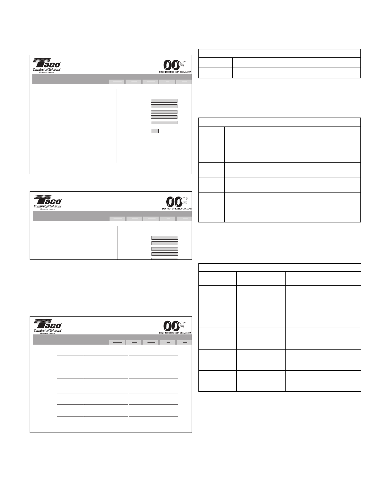
4.4.1 Pump External Control Wiring Diagrams:
The following diagrams are examples of external control wiring to
digital inputs I1 and I2.
4.4.2 External Control Settings:
On/Off/Standby/Max speed external control variances and subse-
quent effects are listed in the chart below. Refer to Section 6.5
Pump Settings to modify digital input and relay settings from fac-
tory defaults.
4.5 Constant 24 Volt DC Power Supply:
There is a constant, unswitched 24Vdc/100mA output power supply
across terminals 24V/0V. This power is interrupted only if the main
power supply to the 00e is turned off.
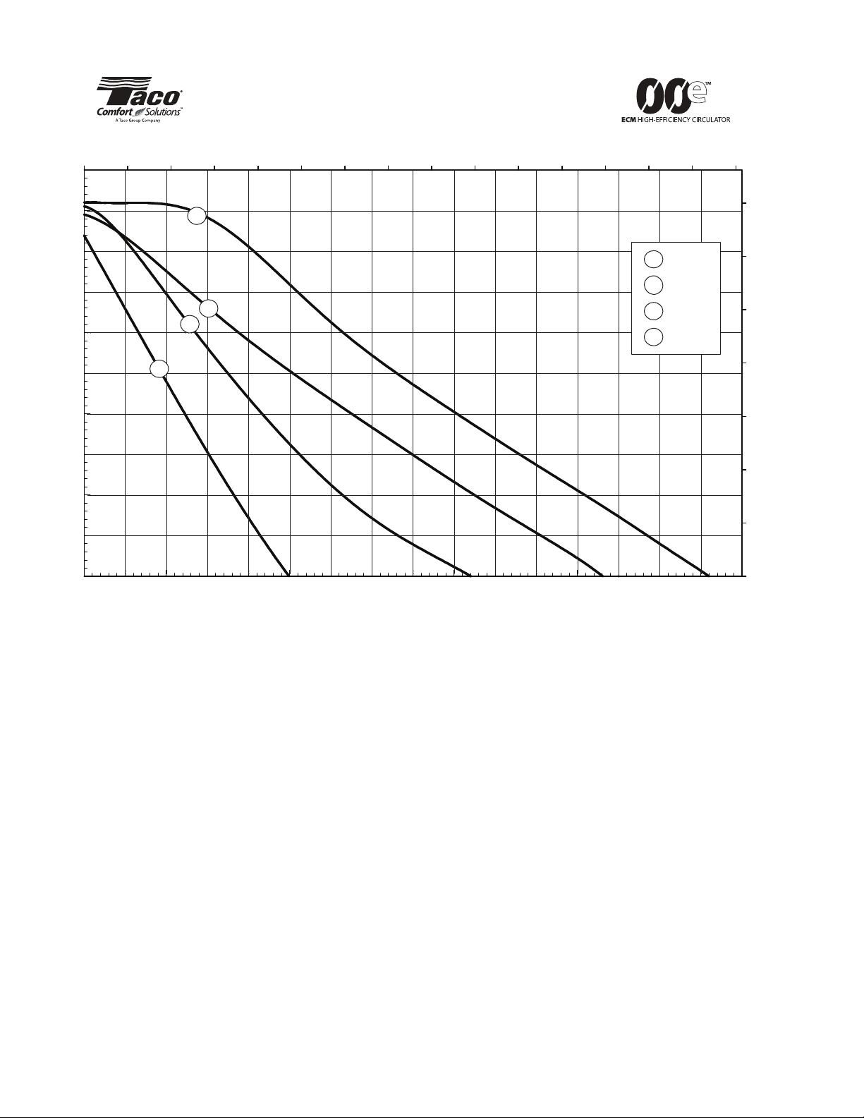
5. REGULATION MODES:
Pump defaults to provide 23 feet (7m) of head with variable differ-
ential pressure (∆p-v) regulation. If the factory settings are not
suitable they can be modified over an Ethernet connector or a web
interface. Various regulation parameters (constant head, supply
power, rpm limit) can adjust the head and flow characteristics until
the pump achieves desired response to suit the application.
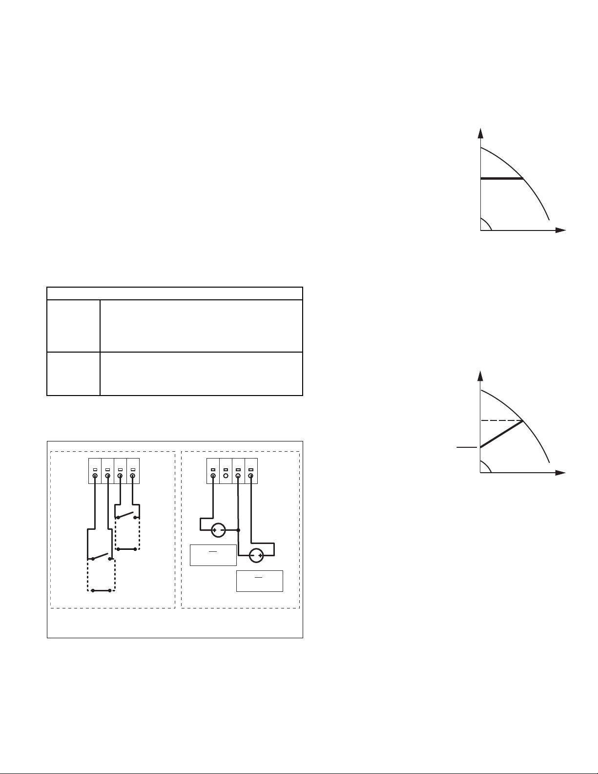
5.1 Constant Pressure Control (∆p -c):
Electronic regulation can provide
constant head by modifying power
input and is set with the Limit
head (Hmax) setting. The duty
point of the pump will move left
and right along a constant-pres-
sure curve based upon the water
demand in the system. The pump
head (pressure) is kept constant,
irrespective of the water demand.
Hmax proportional to Q needs to
be set to 0% (see Section 6
Connection to a Network -
Pump Setup).
Selecting the constant pressure regulation is beneficial when the
00e is installed in a system where there is a much lower resistance
(friction loss) in the main distribution loop compared to the resis-
tance in the transfer part of the system (i.e. baseboard radiation,
radiant floors, terminal units). For example, this characteristic of
generally lower head loss can be found in converted gravity sys-
tems, systems operating with large temperature spreads or where
the pump is moving the total volume of flow through the boiler and
distribution lines.
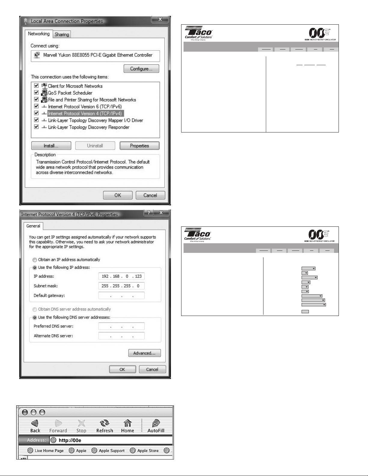
5.2 Variable Differential
Pressure Control (∆p -v)
- Factory Default Setting:
Additional energy savings and
noise reduction is achieved with
proportional head regulation that
also compensates for changes in
system friction losses during peri-
ods of changing flow rates. In this
mode the pump head changes
continuously as the demand for
water changes, reducing as the
water demand declines and
increasing as the water demand rises.
The Hmax proportional to Q setting provides a user adjustable
curve slope. An Hmax proportional to Q of 0% means that the
head does not exhibit any dependence to flow and should not
exhibit noticeable change until maximum power is reached. An
Hmax proportional to Q set to 60% means that the pressure will
drop for 60% from set value when there is no flow. For example if
the head is set to 20', the pump will only provide 12' when the
valves are closed and the pump is dead headed (operating at zero
flow). The factory default is 23' at 50%. Note, a substantial per-
centage of glycol in the mixture can influence regulation.
Select the variable differential pressure control when the 00e is
installed in a system where there is a much higher resistance (fric-
tion loss) in the main distribution loop compared to the resistance
in the transfer part of the system (i.e. baseboard radiation, radiant
floors, terminal units). For example, this characteristic of the prima-
ry circuit having a high pressure drop can be seen in systems using
modulating condensing boilers or heat exchanges, heavily throttled
branch shut-off valves, where the distribution lines are long or in
two pipe systems with thermostatic or zone valves.
FACTORY DEFAULT FUNCTION
I1 (IO1/0V)
Normally open or 2Vdc and less, pump runs normally.
Closing contact (or applying 8Vdc or above) sets the
pump to standby mode by disabling power to the motor
(eg: for Warm Weather Shut own). Additional I1 input
signals are maximum power (speed) and no effect.
I2 (IO2/24V)
Closing I2 or 8Vdc and above (only when I1 is closed)
forces the pump to run at Max (eg: purge system of air
on start-up). Has no effect if I1 is open. Additional I2 input
signals are run and no function.
0
IO2 24 IO1
DC Source
IO1 “Open”
IO2 “Open”
IO2 “Closed”
IO1 “Closed”
Pump Control Using Switches or Other
“Dry” Contacts Such as a Relay
0
IO2 24 IO1
IO2
> 8 Vdc = “Closed”
< 8 Vdc = “Open” DC Source
IO1
> 8 Vdc = “Open”
< 2 Vdc = “Closed”
Pump Control Using a DC Source Such as
From a BMS or Other Controlling
Voltage Source
Note: Maximum voltage on the IO terminals
is not to exceed 32 Vdc
H
Hset
Q
CONSTANT
PRESSURE
CONTROL
H
Hset
Hset
2
Q
PROPORTIONAL
PRESSURE
CONTROL

4
00e STATES
INPUT SETTING INPUT CONNECTIONS PUMP
STATE
RELAY
SETTING
(Default = Error)
RELAY
STATUS
(Normally Open)
IO1 IO2 IO1
Closed: <2 Vdc
IO2
Closed: >8 Vdc
NF (0) NF (0)
OPEN OPEN RUN RUN CLOSED
OPEN CLOSED RUN RUN CLOSED
CLOSED OPEN RUN RUN CLOSED
CLOSED CLOSED RUN RUN CLOSED
RUN NF (0)
OPEN OPEN RUN RUN CLOSED
OPEN CLOSED RUN RUN CLOSED
CLOSE OPEN OFF RUN OPEN
CLOSE CLOSE OFF RUN OPEN
NF (0) RUN
OPEN OPEN OFF RUN OPEN
OPEN CLOSED RUN RUN CLOSED
CLOSE OPEN OFF RUN OPEN
CLOSED CLOSED RUN RUN CLOSED
RUN RUN
OPEN OPEN OFF RUN OPEN
OPEN CLOSED RUN RUN CLOSED
CLOSED OPEN OFF RUN CLOSED
CLOSED CLOSED OFF RUN OPEN
MAX NF (0)
OPEN OPEN MAX RUN CLOSED
OPEN CLOSED MAX RUN CLOSED
CLOSED OPEN RUN RUN CLOSED
CLOSED CLOSED RUN RUN CLOSED
NF (0) MAX
OPEN OPEN RUN RUN CLOSED
OPEN CLOSED MAX RUN CLOSED
CLOSED OPEN RUN RUN CLOSED
CLOSED CLOSED MAX RUN CLOSED
RUN
( efault)
MAX
( efault)
OPEN OPEN RUN RUN CLOSED
OPEN CLOSED MAX RUN CLOSED
CLOSE OPEN OFF RUN OPEN
CLOSE CLOSE OFF RUN OPEN
MAX RUN
OPEN OPEN OFF RUN OPEN
OPEN CLOSED MAX RUN CLOSED
CLOSED CLOSED RUN RUN CLOSED
CLOSED OPEN OFF RUN OPEN
MAX MAX
OPEN OPEN MAX RUN CLOSED
OPEN CLOSED MAX RUN CLOSED
CLOSED OPEN RUN RUN CLOSED
CLOSED CLOSED MAX RUN CLOSED
LEGEND: NF = “No Function” Setting BOLD = Pump Running BOLD ITALIC = Maximum Speed
NOTE : IO1 – “CLOSE ” means connected to 0 - 2 Vdc
IO2 – “CLOSE ” means connected to 8 - 24 Vdc

5
5.3 Constant Duty Curve
(Unregulated Pump)
Control:
An unregulated pump
decreases its head with
increasing flow. This unreg-
ulated setting can be
achieved by setting the limit
head (Hmax) to “no limit
(99)” in the pump tab (see
below) with a jumper across
IO2/24V (or 8Vdc and
above). Note: I1 must be
closed and set to "no function". Limit rpm to should be set to the
maximum value to achieve full pump curve. This allows the pump to
run just like a conventional
non-variable speed pump.
5.4 RPM Regulation:
Provides regulation similar
to a manually adjustable
pump.
5.5 Power Limitation:
Artificially limits power con-
sumption and output by
selecting a maximum amp
draw.
6. CONNECTION TO A NETWORK - PUMP SETUP:
In order to change the factory default operating parameters of the
pump or to use various web tools the pump needs to be connected
to a network or a personal computer over the Ethernet plug. Use
CAT-4 or better network cable connected to “PATCH” configuration
if plugged into a network or connect an Ethernet cable directly
between a PC and the 00e.
To achieve pump IP protection, network cable should be fed
through the glanded inlet and then crimped to a connector.
Ethernet plug is galvanically insulated, but the rest of the cabling
could still present shock hazard.
If more than one pump will be connected into network, each indi-
vidual pump should have its IP address and NetBIOS name
changed and noted. That will prevent network confusion and pro-
vide naming service in relation to pump function.
6.1 Web Interface Settings:
When the 00e is connected to a network or another computer, it
can be reached by typing its IP address or NetBIOS name into the
internet explorer’s address line. The default IP address is
192.168.0.245 and default NetBIOS name is “00e”. The pump can
be switched between standby mode or maximum power via the
digital inputs.
6.2 Setting Up the Default IP Address:
Once the Ethernet cable is connected between the 00e pump and
either the laptop or network, go to your Control Panel and select
Network Connections. Right click on Local Area Connection and
choose properties. Highlight Internet Protocol Version 4
(TCP/IPv4) then click on properties. In the TCP/IP address use the
following IP address “192.168.0.XXX” (example 192.168.0.123).
Click OK to finish.
CAUTION: All connections should be made with
the power to the pump turned off.
ATTENTION: Tous les raccordements doivent être
effectués avec l'alimentation électrique vers la
pompe coupée.
INTERNET
ROUTER ROUTER
LAPTOP
PC
LAPTOP
CONNECTING 00e with ETHERNET CABLE
CONNECTING 00e on LAN
ETHERNET CABLE CONNECTED TO 00E
H
Q
CONSTANT
DUTY
CONTROL
Max RPM or
Unregulated Curve
Reduced RPM
Curves
H
Q
POWER
LIMITATION
CONTROL
Max Power
Curve
Reduced Power
(watt) Curves

6
6.3 Connecting to the Pump:
Go to Internet Explorer, in the address line type http://00e or the IP
address of the pump.
6.4 Overview Page:
The overview page allows you to view the current status of the
pump. You may select the intervals (never, every 30 seconds,
every 3 seconds) of which you would like the data refreshed. It dis-
plays pump operation summary information, including:
• Power Consumption • Heatsink Temperature
• Amperage • Operating Hours
• RPM • Number of Restarts
• Estimated Head • Accumulated Power
• Estimated Flow Consumption
• Estimated Efficiency • igital Inputs
• Motor Status • Relay Status
6.5 Pump Settings:
For more detail or to change any of the pump settings click on the
Pump tab.
Limit head (Hmax) will set the maximum allowable head.
Hmax proportional to Q will set the ratio between head
and flow:
Hmax = 0%: Constant pressure is set and should not exhibit
noticeable change until maximum power is reached.
Hmax = X%: Parameter will set the percentage of drop
in head from maximum to closed valve.
Limit rpm to will limit motor speed.
Limit power to will set maximum wattage (max power
consumption of the pump).
Limit grid current to will assign a maximum amp draw.
Limit heatsink temperature to will set a maximum
temperature at the heatsink (electronics area).
Switch on the relay when can be set up as:
Standby (operation)
Active (run)
Error detected (error)
Active I2 (i2)
Input I1 is either:
Run
Run the pump (run)
Full power (max)
No function (0)
Overview Pump Network Log Help
VR 30
Limit head
adjusts the maximum pump head. The pump will try to maintain that head
between its ports.
Hmax proportional to Q
will reduce the head at the low flow. It will drop for a set percentage at zero
flow.
Limit rpm
can provide a head regulation similar to a manual adjustable pump.
Regulation will reduce the pump power until none of the parameters will be
exceeded.
Regulation settings:
Limit head (Hmax) to feet of head
Hmax proportional to Q %
Limit rpm to /min
Limit power to W
Limit grid current to A
Limit heatsink temperature to °F
Switch on the relay when
Input I1 is:
Input I2 is:
C
23.0
50
3000
1600
8.0
203
error
run
max
Save
series
Overview Pump Network Log Help
Welcome!
You have reached VR 30 circulating pump. It is connected to
network with IP 192.168.0.245 and MAC 02-1A-6F-EF-FB-BA.
Pump status is available on the right. In order to refresh the view, press
browser's refresh button or choose automatic refresh.
Pump Status:
Refresh the view: never | every 30s | every 3s
Operation:
Power consumption: 251 W (1600 W)
Grid current: 1.09 A (8.0 A)
RPM: 1645/min (3000/min)
Estimated head: 13.1 ft. of head (13.3 ft. of head)
Estimated flow: 30.7 GPM
Estimated efficiency: 30 %
Temperatures:
Motor: OK
Heatsink: 91 °F (203 °F)
Statistics:
Operating hours: 4 h
Number of restarts: 13
Energy consumed: 1 kWh
Control:
Digital inputs: 1 (run), 0 (max)
Relay status: 0 (error)
Twin pump mode: N/A (-4)
series

7
Input I2 has the functions the same as I1.
SAVE will write settings in permanent non-volitile memory.
6.6 Network Settings:
This page provides a way to change network configurations.
Buttons operate in a similar manner as on previous pages.
6.7 Log:
This page will display possible errors.
6.7.1 Errors:
By clicking on either current error or last error you are brought to
a page detailing the errors, the probable cause and possible solu-
tion. Also, errors can be viewed without having to connect to the
pump through an Ethernet cable or the internet. A control light on
the front panel provides fast overview of pump operation. The blue
color signifies correct operation while the sequence of a blinking
red indicates an error.
6.8 Help:
This page will redirect you to www.taco-hvac.com. Possible soft-
ware upgrades and manuals will be available.
7. DIAGNOSTIC AND OPERATING LIGHTS:
A control light on the front panel provides fast overview of pump
operation. The blue color signifies correct operation while red indi-
cates an error.
7.1 Red Light:
A red light blinks to indicate an error code. The sequence of the
blinks is interrupted by a pause. The number of blinks between
pauses is the error code.
7.2 Overload Effects and Reset:
Overload is indicated by the blue power light changing to red. The
red overload light flashes in accordance to the failure. The last
overload is saved in memory.
8. SEARCH FOR A “LOST PUMP”:
If you have forgotten the IP address or NetBIOS name or if you
accidently set it to an incorrect value, a pump can still be found
with network analyzers. Freeware tools like “WireShark” or
“Ether etect” can help you to trace the pump as it periodically tries
to contact its twin. This is true even in the case of a single pump.
You can trace out the device that sends out requests and contact
it directly.
BLUE LIGHT
Blinking Pump is in standby mode and not pumping water.
Solid On Pump is operating as set
RED LIGHT
ERROR
CODE DESCRIPTION
1
Motor is operating under very low load conditions. This indi-
cates that the pump is probably running dry. System may
need filling or air purged.
2Pump cannot start. Rotor might be blocked. Remove head
of pump and check if the impeller turns freely.
3Motor has overheated. Too hot of a medium, over estimat-
ed head of pump requirements or nonfunctioning motor.
4 Frequency converter error.
5 Stator or rotor faulty.
Overview Pump Network Log Help
ERROR CODE DESCRIPTION PROBABLE CAUSE AND SOLUTION
(*)1 Low load detected
The pump might be running dry. Make
sure the system is filled with fluid to
prevent bearing damage.
(**)2 Overload trip, protective shutdown
Overcurrent, line surge or locked rotor
caused the pump to restart. If the issue
persists, check if the rotor is spinning freely
(***)3 Motor too hot
Motor has exceeded allowed temperature
and is now stopped to cool down.
Extremely hot medium or hardware failure
might have caused that.
(****)4 Frequency converter error
Converter has detected an internal fault.
The pump might still be operating, but
needs repair.
(*****)5 5 Motor/stator faulty
Motor does not behave as expected.
Internal winding or wiring error might have
caused that.
Content ©copyright 2011 Taco Inc., 1160 Cranston, RI USA 02920 • www.taco-hvac.com
series
Overview Pump Network Log Help
VR 30
IP address
is a pump network address. The pump is seen as http server on this address.
Subnet mask
sets subnet address range that is on the same subnet and can be reached
directly. The rest of communication goes over the gateway.
Default gateway
provides connection route to larger networks. This is usually a router
address.
NetBIOS name
is a local network name server. Instead of '192.168.0.245' you can for
example use 'http://00e'.
Twin mode IP
will connect two pumps for alternating operation. When two pumps are
configured for twin mode, they will switch about once per day. Setting this
field to unexistent IP will disable this option. Set it so the first pump
references the second and vice versa.
(!)Use 'Save' carefully. Incorrect settings might render pump unreachable. If
you change the IP address, you will need to manually enter it into browser
window.
Network connection settings:
Pump IP address:
Subnet mask:
Default gateway:
NetBIOS name:
Twin mode with IP:
Content ©copyright 2016 Taco Inc., 1160 Cranston, RI USA 02920 •
www.taco-hvac.com
192.168.0.245
255.255.0.0
192.168.0.1
00e
0.0.0.1
Save
series
Overview Pump Network Log Help
VR 15
IP address
is a pump network address. The pump is seen as http server on this address.
Subnet mask
sets subnet address range that is on the same subnet and can be reached
directly. The rest of communication goes over the gateway.
Default gateway
provides connection route to larger networks. This is usually a router
address.
N
Network connection settings:
Pump IP address:
Subnet mask:
Default gateway:
NetBIOS name:
Twin mode with IP:
192.168.0.245
255.255.0.0
192.168.0.1
00e
192 168 0 246
series
OVERLOAD EFFECTS AND RESET
DESCRIPTION OVERLOAD
EFFECT
RESET
REQUIREMENT
Low Load
(dry run)
Pump runs at
reduced speed after
approx 60 seconds.
Runs at normal speed once
motor load is increased (water in
volute).
Overload
(locked rotor) Pump shuts off.
Manual (turn main power supply
off/on). Clear obstructions if nec-
essary.
Motor Overheat
Pump runs at
reduced power until
motor cools down.
Cool motor.
VF Failure Pump shuts off.
Manual (turn main power off/on).
If unable to reset, replace pump
(powerhead).
Motor/Stator
Failure Pump shuts off.
Manual (turn main power off/on).
If unable to reset, replace pump
(powerhead).

8
9. PARALLEL (MAIN/STANDBY) INSTALLATION:
Prior to connecting the pumps via the Ethernet Crossover cable,
program each pump’s “Pump IP address” and “Twin mode with IP”
addresses. See 9.1 and 9.2 below.
NOTE: It is highly recommended that if the pump IP address
(and/or the Net BIOS name) is modified from factory default set-
ings then these changes are recorded and the change is posted
on the pump itself.
Reprogramming the pumps needs to be completed to each pump
individually prior to connecting the pumps together. See Section 6,
Subsection 6.6 Network Settings. A standard Ethernet or Ethernet
Crossover cable can be used to reprogram each pump.
Once completed:
• One pump will run and show a blue light.
• The second pump will be on standby mode indicated by a
flashing blue light (drive is enabled and the motor is disabled).
• An automatic alternation between the two pumps will occur
every 24 run-hours. This is not adjustable and is a factory
default.
To confirm communication between the pumps once reprogramming
is complete and the Ethernet Crossover is connected:
• Observe the blue power lights on the face of the drives. One is
on constantly and the other pulses.
• Observe the two communication lights at the RJ-45 Ethernet
connection in each pump’s terminal box. Both pumps should
have one LE on continually with the second LE pulsing
(indicating intercommunication).
• To confirm communication, turn off the main power supply to
the running pump. After 10 to 15 seconds, the second pump
will switch from standby to on (flashing blue light changes to
solid blue and the motor starts).
• Once communication is confirmed, turn on the power prior to
leaving the job site. This pump will now be in standby mode
(flashing blue light).
Notes:
Both pumps should be the same size and “Head Max” and
“Proportional %” set to the same value. See Section 6, Subsection
6.5 Pump Settings.
This is main/standby operation only. Both pumps will not run at the
same time as long as the Ethernet Crossover cable is connected.
9.1 IP Settings for Main/Standby Operation – P1:
9.2 IP Settings for Main/Standby Operation – P2:
10. 00E WIRELESS ROUTER SETTINGS:
The following are instructions to set up an external wireless router to
communicate with a 00e Pump.
Follow the instructions that came with the router to perform modifica-
tions required in LAN settings and wireless settings.
Shown here is the Netgear WN R3700, but many routers have sim-
ilar interfaces. Note that this will NOT provide internet service to
your laptop or mobile device NOR will it make the 00e accessi-
ble over the internet.
10.1 Wireless Setting:
This is where it is possible to personalize the name of the wireless
network. The example below illustrates a network called “00e
Wireless”. Regardless of the wireless network name, once set-up,
the wireless device (iPhone, iPad, PC, Mac or Android device) is
directed to connect to that network (“00e Wireless” as an exam-
ple).
Overview Pump Network Log Help
VR 15
IP address
is a pump network address. The pump is seen as http server on this address.
Subnet mask
sets subnet address range that is on the same subnet and can be reached
directly. The rest of communication goes over the gateway.
Default gateway
provides connection route to larger networks. This is usually a router
address.
NetBIOS name
is a local network name server. Instead of '192.168.0.245' you can for
example use 'http://00e'.
Twin mode IP
will connect two pumps for alternating operation. When two pumps are
configured for twin mode, they will switch about once per day. Setting this
field to unexistent IP will disable this option. Set it so the first pump
references the second and vice versa.
(!)Use 'Save' carefully. Incorrect settings might render pump unreachable. If
you change the IP address, you will need to manually enter it into browser
window.
Network connection settings:
Pump IP address:
Subnet mask:
Default gateway:
NetBIOS name:
Twin mode with IP:
192.168.0.245
255.255.0.0
192.168.0.1
00e
192.168.0.246
Save
series
Overview Pump Network Log Help
VR 15
IP address
is a pump network address. The pump is seen as http server on this address.
Subnet mask
sets subnet address range that is on the same subnet and can be reached
directly. The rest of communication goes over the gateway.
Default gateway
provides connection route to larger networks. This is usually a router
address.
NetBIOS name
is a local network name server. Instead of '192.168.0.245' you can for
example use 'http://00e'.
Twin mode IP
will connect two pumps for alternating operation. When two pumps are
configured for twin mode, they will switch about once per day. Setting this
field to unexistent IP will disable this option. Set it so the first pump
references the second and vice versa.
(!)Use 'Save' carefully. Incorrect settings might render pump unreachable. If
you change the IP address, you will need to manually enter it into browser
window.
Network connection settings:
Pump IP address:
Subnet mask:
Default gateway:
NetBIOS name:
Twin mode with IP:
Content ©copyright 2016 Taco Inc 1160 Cranston RI USA 02920 • www.taco-hvac.com
192.168.0.246
255.255.0.0
192.168.0.1
00e
192.168.0.245
Save
series

10.2 LAN (Local Area Network) Setting:
The factory default IP Address of the 00e is 192.168.0.245. It is not
necessary to change this unless multiple 00es are connected to
the same router. See Notes below.
Set Router LAN TCP/IP as follows:
• IP Address 192.168.0.1
• IP Subnet mask 255.255.255.0
Set Router HCP as follows:
• Check “Use Router as HCP Server” box
• Starting IP Address 192.168.0.2
• Ending IP Address 192.168.0.100
10.3 Steps to Communicate with the 00e After Changes are
Complete:
Plug in an Ethernet cable to the device input at the back of the
router (not the Internet or “WAN” input) and to the Ethernet con-
nection at the 00e.
Power up all devices (the 00e can be forced into standby by plac-
ing a jumper across I01 and 0V digital input to eliminate dry oper-
ation of the rotating assembly).
Connect to the wireless network with the iPhone (or other wireless
device), using the network name set in the “Wireless Setting” section.
Open up the device web software (Safari, Windows Explorer,
Firefox etc.).
Open the website “00e” or enter the pump’s IP Address
192.168.0.245 in the address window, click enter.
Connection is complete and status or adjustments to the 00e can
be made.
Notes:
Multiple 00es can be plugged into the router, although each pump
would require a different IP address and name.
No other changes to the router are required from factory settings.
11. SPECIFICATIONS AND PUMP CHARACTERISTICS:
11.1 Application:
• Maximum Operating Pressure: 175 PSI (12 bar)
• Water Temperature Range: 14º – 230ºF (-10º – 110ºC)
• Ambient Operation Temperature Range: 32º – 104ºF
(0º – 40ºC). Ambient temperature should be 104ºF (40ºC)
or lower when fluid temperature exceeds 194ºF (90ºC).
• Minimum static inlet pressure at pump suction port
(PSI / bar) to avoid cavitation at fluid temperatures:
• esigned for closed loop heating and cooling systems
pumping water or a water/glycol mixture.
• For indoor use only - employer uniquement a l’interieur.
11.2 Electrical Data:
• Pump Ratings: 1 phase, 110 - 240V, 47 - 63Hz (VR15 & VR20)
1 phase, 200 - 240V, 47 - 63Hz (VR25 & VR30)
• Power Consumption (HP): VR15 = 0.027 - 0.680 HP
VR20 = 0.035 - 1.088 HP
VR25 = 0.054 - 1.496 HP
VR30 = 0.054 - 2.175 HP
• Power Consumption (W): VR15 = 20 - 500 W
VR20 = 26 - 800 W
VR25 = 46 - 1100 W
VR30 = 40 - 1600 W
• Rated Current (1 phase, 115/230V): VR15 = 2.2 A - 6.0 A
VR20 = 3.5 A - 6.0 A
• Rated Current (1 phase, 230V): VR25 = 8.0 A
VR30 = 8.0 A
• 24V Supply Output: Max. Current up to 100 mA,
Output Voltage of 24V ± 20%,
Output Ripple under 1V
• Relay Output: 8A, Max. Voltage 250 VAC, 48 V C
Max. Load up to 500 VA
• igital Inputs: Max. Input Voltage = 32V C
Input Impedance ~5kΩ
Logical »1« Voltage > 8V
Logical »0« Voltage < 2V
Insulation to Supply Voltage = 4kV @ 1s,
275V permanent
• Continuous uty
• Built-in Startup Circuit
11.3 Standards, Protection and Connection:
• Insulation: Class H
• Enclosure: Class 2, IP44
• Integrated Motor Protection (electronically protected)
• UL 778, 1004-1, 508C
• CAN/CSA C22.2 #108, #100, #107.1
• EMC (89/366 EEC): EN 61000
• LV (73/23/EC): EN 60335-1, EN 60335-2-51
• Machine Safety (98/37/EC): EN ISO 12100
• Flange Connections: ANSI 4-bolt
11.4 Ethernet Specifications:
• Connector: RJ-45 Ethernet Cable
• Speed: BASE-10, 10 Mbit/s
• Galvanic Insulation to igital Inputs: 1.5kV @ 1s, 48V permanent
• Galvanic Insulation to Line Voltage: 4kV @ 1s,
275V permanent
• Connections: TCP/IP
• Services: http server and client, FTP server
• Web Language: HTML 1.1
11.5 Materials of Construction:
• Casing: Cast Iron
• Impeller: Stainless Steel
• Shaft: Stainless Steel
• Bearing: Metal Impregnated Carbon
11.6 Operating Modes:
• Constant Pressure Control (∆p-c)
• Variable ifferential Pressure Control (∆p-v) - factory
default
• Proportional Pressure Control
• Constant Curve uty (uncontrolled pump)
• RPM Regulation
• Power Limitation
11.7 Additional Operating Modes for Two Pumps in Parallel:
• Alternating Operation (every 24 hours)
• Standby Operation
11.8 Communication:
• Web Interface (data exchange)
• XML Control Transfer Protocol
• External igital Input/Output: 2 Inputs & 1 Output
9
FLUID
TEMPERATURES
VR15 & VR20
(PSI / bar)
VR25 & VR30
(PSI / bar)
112ºF (50ºC) 7.3 / 0.5 4.35 / 0.3
176ºF (80ºC) 11.6 / 0.8 14.5 / 1.0
230ºF (110ºC) 20.3 / 1.4 23.2 / 1.6

10
00e 15-30 PERFORMANCE CURVES
series
FLOW (GPM)
0255075100 125150175200 225 250 275 300 325 350 375 400
HEAD (FT.)
0
5
10
15
20
25
30
35
40
45
50
Flow (liter/min)
0 100 200300400500 600 70080090010001100 1200 13001400150
0
Head (m)
0
2
4
6
8
10
12
14
Performance
3
4
1VR15
3VR25
4VR30
2VR20
1
2

11
NOTES:

12
Taco, Inc. will repair or replace without charge
(at the company’s option) any product or part
which is proven defective under normal use with-
in one (1) year from the date of start-up or one
(1) year and six (6) months from date of ship-
ment (whichever occurs first).
In order to obtain service under this warranty, it
is the responsibility of the purchaser to promptly
notify the local Taco stocking distributor or Taco
in writing and promptly deliver the subject prod-
uct or part, delivery prepaid, to the stocking dis-
tributor. For assistance on warranty returns, the
purchaser may either contact the local Taco
stocking distributor or Taco. If the subject prod-
uct or part contains no defect as covered in this
warranty, the purchaser will be billed for parts
and labor charges in effect at time of factory
examination and repair.
Any Taco product or part not installed or operat-
ed in conformity with Taco instructions or which
has been subject to misuse, misapplication, the
addition of petroleum-based fluids or certain
chemical additives to the systems, or other
abuse, will not be covered by this warranty.
If in doubt as to whether a particular substance
is suitable for use with a Taco product or part, or
for any application restrictions, consult the
applicable Taco instruction sheets or contact
Taco at [401-942-8000].
Taco reserves the right to provide replacement
products and parts which are substantially similar
in design and functionally equivalent to the defec-
tive product or part. Taco reserves the right to
make changes in details of design, construction,
or arrangement of materials of its products with-
out notification.
TACO OFFERS THIS WARRANTY IN LIEU OF
ALL OTHER EXPRESS WARRANTIES. ANY
WARRANTY IMPLIED BY LAW INCLUDING
WARRANTIES OF MERCHANTABILITY OR
FITNESS IS IN EFFECT ONLY FOR THE DURA-
TION OF THE EXPRESS WARRANTY SET
FORTH IN THE FIRST PARAGRAPH ABOVE.
THE ABOVE WARRANTIES ARE IN LIEU OF
ALL OTHER WARRANTIES, EXPRESS OR
STATUTORY, OR ANY OTHER WARRANTY
OBLIGATION ON THE PART OF TACO.
TACO WILL NOT BE LIABLE FOR ANY SPE-
CIAL, INCIDENTAL, INDIRECT OR CONSE-
QUENTIAL DAMAGES RESULTING FROM THE
USE OF ITS PRODUCTS OR ANY INCIDENTAL
COSTS OF REMOVING OR REPLACING
DEFECTIVE PRODUCTS.
This warranty gives the purchaser specific rights,
and the purchaser may have other rights which
vary from state to state. Some states do not
allow limitations on how long an implied warranty
lasts or on the exclusion of incidental or conse-
quential damages, so these limitations or exclu-
sions may not apply to you.
LIMITED WARRANTY STATEMENT
NOTES:
This manual suits for next models
3
Table of contents
Other Taco Comfort Solutions Water Pump manuals
Popular Water Pump manuals by other brands

GORMAN-RUPP PUMPS
GORMAN-RUPP PUMPS 0 Series Installation, operation, and maintenance manual with parts list

EINHELL
EINHELL GC-DP 3730 Original operating instructions

Pentair
Pentair FAIRBANKS NIJHUIS 1590F Instruction and installation manual

Graco
Graco L20c Operation

Pfeiffer Vacuum
Pfeiffer Vacuum OKTA 1000 ATEX operating instructions

Neptun
Neptun NCTP-O 5000 operating instructions