Takahashi Mewlon-180C User manual

Instruction Manual
TAKAHASHI

- 2 -
Thank you very much for your purchase of the Takahashi Mewlon-
180C telescope. This model is the lightest and most compact one
in all Mewlon series with 50.8(2") system provided. The mirrors are
coated with a HR multi-layer coating.
In order to use the telescope to its highest possible capabilities,
please read this instruction manual very carefully and familiarize
yourself with all of the functions that your telescope oers.
All Takahashi telescopes have been strictly inspected before
shipment. If there is any trouble with your telescope when
unpacked, please contact your authorized dealers for proper
attention.

WARNING
CAUTION
- 3 -
If a telescope is pointed at the sun, its
light and heat concentrated at the focal
point will be intense and dangerous.
NEVER LOOK THE SUN DIRECTLY.
VIEWING THE SUN WITHOUT PROPER
FILTERS MAY RESULT IN BLINDNESS.
DANGER
◆ When attaching the tube assembly onto the equatorial
mount, be careful not to pinch your ngers or to drop the tube
assembly.
◆ Always lay the tube assembly on a completely at surface that
totally supports it to protect it from damage.
◆ Keep the tube assembly out of the sun to prevent the light of the
sun going into the tube, the reected sunshine can cause great
heat at the focal point and become so intense that it could start
a re.
◆ When focusing, be careful not to pinch your ngers.
◆ Keep children away from small parts that could be swallowed
and keep them away from plastic bag that covers the tube
assembly.
◆ Keep away all packing materials from an open flame. These
materials are ammable.
Precautions for Safe Operation

- 4 -
Contents
Precautions for Safe Operation ----------------------- 3
Contents ----------------------------------------------------- 4
Specications ---------------------------------------------- 5
Tube Assembly Layout ---------------------------------- 6
Features ----------------------------------------------------- 7
Setup Procedures ----------------------------------------- 8
Focusing ----------------------------------------------------- 11
Finder Adjustment ---------------------------------------- 12
Observation ------------------------------------------------ 14
Accessories ------------------------------------------------ 15
Collimation -------------------------------------------------- 18
Care & Maintenance ------------------------------------- 20
System Charts --------------------------------------------- 21

- 5 -
Specications
Optical System -------------------- Dall Kirkham
Eective Aperture ----------------- 180mm HR Multi-Coated
Eective Focal Length ----------- 2160mm
Eective Focal Ratio ------------- 1:12.0
Secondary Mirror ------------------ 54mm HR Multi-Coated
Resolving Power ------------------ 0.64"
Limiting Magnitude --------------- 13.0
Light Gathering Power ----------- 661x
When used with Mewlon Flattener/Reducer
Eective Focal Length --------- 1760
Eective Focal Ratio ------------ 1:9.8
Tube Diameter --------------------- 210mm
Total Length of Tube ------------- 625mm
Total Weight of Tube ------------- 6.2kg (13.6lbs)
Finder Scope ----------------------- 6x30 built-in
Accessories ------------------------ Dove-tail Adapter (F),
Warranty Card, Instruction Manual,
Tools (Hex Wrench 1.5mm & 2.5mm)
(Note) HR = High Reectance

- 6 -
Tube Assembly Layout
Main Tube
6x30 Finder Scope
Dove-Tail
Adapter (M)
50.8(2”) Sleeve
Coupling (S)
Eyepiece Adapter Cap
31.7(1¼”) Eyepiece Adapter

- 7 -
Features
The Mewlon-180C is a Dall-Kirkham optical
system best used visually for lunar and
planetary observation, as well as imaging,
and can be used for observation of deep
space objects. The classical Cassegrain
optical system uses a parabolic concave
primary mirror and a convex hyperbolic
secondary. This design eliminates spherical
aberration, but it is difficult to produce the
hyperbolic secondary and collimation is
difficult. The Dall Kirkham design uses
a concave elliptical primary mirror and a
convex spherical secondary, so that any
spherical aberration is corrected by this
design approach using both mirrors for
correction.
There is only trace spherical aberration in
the center of the field of view of the Dall
Kirkham, but towards the edge, there is
increasing coma. In order to minimize the
coma, the magnifying ratio of the secondary
should be made smaller. The Mewlon-180C
is designed with a long focal ratio of f/12
with an f/3 primary, a 4x secondary, plus an
additional 10 baffles in the primary mirror
baffle to reduce internal reflections and off
axis coma.
The Dall Kirkham optical design is best
suited for lunar and planetary viewing as
well as the observation of small deep space
objects that require higher magnification.
However, the Dall-Kirkham is capable
of producing images as good as those
produced by a Newtonian reflector. This
design can produce images visually, and
by using CCD camera, Takahashi has
successfully developed a compact and easy
to use telescope for planet images of the
highest quality.
Th e s phe ric a l sec ond a ry mi rro r has
allowed the mirror making, assembling, and
adjusting of the Dall-Kirkham to become
easier. This has enabled Takahashi to
provide high performance on a continuous
basis. Additionally, a paring system is
used to insure the best match between
the primary and the secondary as they
are produced as closely possible at the
same time and due to this pairing, there is
no quality difference between the mating
mirrors. The new HR multi-layer mirror
coating increases reflectivity by 7% as
compared to the original Mewlon-180.
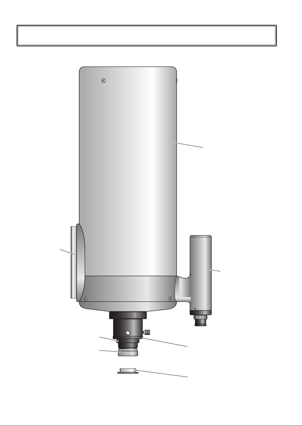
The Mewlon-180C tube is an open tube
telescope. Since there is no corrector plate
over the front of the tube, the mirror can
equalize with the ambient temperature which
will stabilize quickly, and the air inside the
tube will stabilize turbulence. The Mewlon-
180C, with its long focal length, will produce
sharp high contrast images of the Moon and
planets. Ten baes have been placed inside
the primary baffle tube to produce images
with great contrast and excellent sharpness.
When the tube assembly is attached to the
mount, the Mewlon holder has one part, the
dove-tail attached to the tube assembly and
the detached saddle plate which is attached
to the mount. The tube assembly can be
conveniently attached and removed from
the mount, using this dove-tail system.

- 8 -
◆Attaching the Tube Assembly onto the Mount
Setup Procedures
Attach the dove-tail adapter (F) rmly on the
mount with two cap bolts as shown.
Loosen the Dec. clamp so the dove-tail
adapter (F) is positioned as illustrated below
and lock it rmly.
Dove-Taile Adapter (F)
Clamp Handle
Cap Bolt
Hex Wrench
Tube Holder Base
Dec. Clamp
The finder scope is built-i n the t ube
assembly and is designed as the carrying
handle. When setting the tube assembly
on the mount, carry it with two hands as
illustrated below.
Dove-Taile Adapter (F) Clamp Handle
Tube Holder Base
Mount
Clamp Handle

- 9 -
◆Balancing
After the tube assembly has been attached on the mount, the next step is to balance it in
the R.A. and Dec. axes. If unbalanced, the clamps will not work eectively and the tube
assembly will abruptly and dangerously turn. When the motor of the mount is rotating,
unbalancing will cause gearing trouble that will make the life of the mount shorter. When
balancing, do it with all accessories necessary for observation attached to the tube
assembly.
▼Balancing around the Dec. axis
1. Loosen the Dec. clamp and lock it at
the position that the Dec. axis becomes
horizontal.
2. Loosen the handle of the dove-tail
adapter (F) and move the tube assembly
forward and backward until it balances.
In the normal visual observation, place
the tube assembly at the top of the dove-
tail adapter as illustrated.
▼Balancing around the R.A. axis
1. When balancing around the Dec. axis
has been made, lock the Dec. clamp
rmly.
2.
Loosen the R.A. clamp and see balancing
around the R.A. axis.
3. If unbalanced, move the counter-weight
until it balances and lock the R.A. axis.
4. If unbalanced at the top of the counter-
weight shaft, add an extra weight to
balance.

- 10 -
◆Attaching an Eyepiece
Loosen the compression ring and insert an
eyepiece into the eyepiece adapter. Then,
tighten the compression ring to lock the
eyepiece.
◆Eyepieces
A wide variation of eyepieces are available
from Takahashi.
▼LE Series
Standard type, wide view field and high
magnication. Available in:
・31.7mm (1¼”) barrel
LE5mm, LE7.5mm, LE10mm, LE12.5mm,
LE18mm, LE24mm, LE30mm
・50.8mm (2”) barrel
LE50mm
▼HI-LE Series
Long eye-relief, most suitable for planetary
observation with high magnification.
Available in:
・31.7mm (1¼”) barrel
HI-LE2.8mm, HI-LE3.6mm
▼Abbe Series
Simple 2-group 4-element eyepieces with
high contrast, less expensive with high
performance. Available in:
・31.7mm (1¼”) barrel
Abbe 4mm, Abbe 6mm, Abbe 9mm,
Abbe 12.5mm, Abbe 18mm, Abbe 25mm,
Abbe 32mm
◆Attaching Accessories
Adapters and rings are attached to the visual
back in order to use various accessories.
Please check the system charts and attach
the desired accessories correctly. Standard
connection is as below.
▼Ere
With 3-group 5-element optics, offering 60
degree apparent field of view, almost no
are and ghosting. Available in:
・31.7mm (1¼”) barrel
Er-28mm
▼TAK-UW Series
Ultra-wide angle with apparent field of
90 degree designed to get sharpest star
images. Available in:
・31.7mm (1¼”) barrel
TAK-3.3UW, TAK-5.7UW, TAK-7UW,
TAK-10UW
Compression Ring
Plastic Ring
Eyepiece
50.8(2”)Sleeve
Coupling (S)
31.7(1¼”) Eyepiece Adapter
Eyepiece
50.8mm (2”)
M43x0.75
M36.5x1.0 31.7mm (1¼”)

- 11 -
Focusing
◆Focusing System
Focusing this optical system is done by
moving the primary mirror forward and
backward using the focusing knob. The
relation of the motion direction of the
primary mirror and the focal point is as
illustrated below.
When the focusing knob is turned counter-
clockwise (OUT), the primary mirror is
moved toward the secondary and then, the
focal plane is moved outward. When the
focusing knob is turned clockwise (IN), the
primary mirror is moved toward mirror cell
and then, the focal plane is moved inward.
After an eyepiece has been attached on your telescope, precise focusing is needed to
observe objects and landscapes clearly. If not correctly focused, your telescope cannot
display its capabilities. Precise focusing is absolutely necessary especially in astro-imaging.
Always use the best possible focus with the following procedures.
Caution
The optical axis of the Mewlon-180C
could become decollimated if the
Mewlon is subjected to strong shocks
during transport. In order to prevent
the telescope from decollimating, the
primary mirror is moved to the mirror
cell. So, when focusing, turn the
focusing knob in the OUT direction
(counter-clockwise).
O
U
T
I
N
O
U
T
I
N
OUT
Focal Plane
Focal Plane
IN

Finder Adjustment
The eld of view of a telescope can be highly magnied and narrow so that it is dicult to
place an object in the eld of view. In order to help you to nd the object easily in the view
eld of your telescope, a 6x30 nder scope with wide eld is provided with your telescope.
In order to see the same object in the view eld of the main telescope and the nder scope,
you must align the optical axes of the main telescope and of the nder scope. They must
be parallel each other and then you can see the same object in the view field of both
telescopes.
The nder scope attached to the tube assembly can be used also as the carrying handle.
The nder can be adjusted by shifting the focusing unit using the adjusting screws. This
system will hold the collimation of the nder to the main scope, but when necessary, realign
the nder and main scope using the following procedure.
- 12 -
Finder Adjusting Screw Lock Ring
Focus Lock Ring
Eyepiece
Finder
Field of View of the Finder
Field of View of
the Main Telescope
◆Collimating the Optical Axis
The nder scope has been collimated at the
factory before shipment. Therefore, usually
the collimation is not needed when you
purchase your telescope. However, if the
collimation should be lost by some reason,
you can adjust the collimation with the
following procedures.
1. Set your telescope for visual use and
attach a low power eyepiece. Then,
center a distinct object as far away as
possible in the eld of view.
2. Change the eyepiece to one of higher
power ones and center the object again.
Then, lock the telescope's (illustration
at the right) field of view of the finder
scope and to the eld of view of the main
telescope.
◆Adjusting Focusing System
When you observe distant objects, you can
adjust focus as follows.
1. Loosen the focus lock ring.
2. Find the focal point by turning the visual
back clockwise and counter-clockwise,
viewing the distant object.
3. When focused sharply, tighten the focus
lock ring.

Hex Wrench
Loosen
3. If the object is not centered in the field
of view of both telescopes, adjust the
nder using the following method so that
the object is placed at the center of the
crosshair.
4. Loosen the lock ring as illustrated.
5. Loosen all three adjusting screws enough
so that the eyepiece can move freely.
6. Hold the visual back with one hand and
adjust it so that the object at the center
of the telescope is on the crosshair in the
center of the finder, looking through the
finder. Then, lightly tighten the lock ring
with the other hand.
7. By turning all three adjusting screws
with the Hex wrench, center the object
precisely at the crosshair. If the object
shifts as illustrated; loosen screw A and
tighten B & C screws to move the object
on the crosshair. When the object is
positioned on the crosshair, tighten the
adjusting screws rmly.
8. Finally, tighten the lock ring firmly and
lock the visual back.
*Please understand the relationship
between the movements of the three
adjusting screws and the movement of the
object in the eld of view, actually looking
into the nder.
*
Please do the above procedures in the
daytime to be ready for observation at night.
*When the finder alignment is made
by using a star, it will move during the
alignment procedure due to the movement
of the sky. Therefore, do alignment rapidly
or use an equatorial mount with the motor
drive running to keep the stars from
moving in the eld of view.
A
B
C

Observation
◆Preparation before Observing
A reflecting telescope like Mewlon-180C
takes time to equalize the optical system
with the ambient outside air temperature,
especially when the outside temperature is
low. Bring the tube assembly outside about
one hour before observation and allow it
to equalize with the outside ambient air
temperature.
◆Visual Observation
▼Magnication
Magnication can be computed by using the
following formula.
Focal Length of Telescope divided by
the Focal Length of the Eyepiece
For example with LE18mm eyepiece
2160mm / 18mm = 120
Therefore, the shorter the focal length
of an eyepiece is used, the higher the
magnication. On the other hand, the longer
the focal length of an eyepiece is used, the
lower the magnication. It is a general rule
that the upper limit of the magnification is
20x to the aperture in "cm" of a telescope
and the lower limit is 1.4x to it. Therefore,
the highest effective magnification of your
Mewlon-180C will be 360x and the lowest
26x. Most of Takahashi eyepieces can cover
this magnication range.
▼Diagonal Mirror & Diagonal Prism
A diagonal mirror or a diagonal prism make
it easy to observe comfortably. These are 90
degree diagonals, which are available from
Takahashi. Further details of these parts,
please refer to the next page.
◆Astro Imaging
▼Magnied Imaging
When imaging the craters of the Moon and
planets, magnied imaging can be done with
the parts optionally available. When imaging
the Moon's surface, you can enjoy a wide
variation of imaging because the Moon has
ample illumination. In the case of planetary
imaging, magnify it as large as possible
according to seeing and illumination. When
the seeing is bad, good imaging of the
moon as well as planets will be impossible.
Therefore, visually check the seeing before
imaging and do it in when the conditions as
good as possible. For magnified imaging,
the TCA-4 is available from Takahashi
together with various T-mounts to attach
your DSLR camera to your telescope.
▼Prime Focus Imaging
This is the method used to image an object
that is focused by placing the imaging
element at the prime focal point. In this
method, a telescope is used as a telephoto
lens for your camera. When Mewlon-180C is
used as a telephoto lens with a camera, its
focal length is so long that it will make star
images degraded with even a slight error
in guiding. Use a sturdy, quality equatorial
mount like the Takahashi EM-200 T-2Z.
Cameras that can do prime focus imaging
are the DSLR and CCD cameras available
in the astro market. Various adapters to
attach a camera to Mewlon-180C are
available from Takahashi. Please refer to
the system charts for further information.
- 14 -

Length of Light Pass
81.0mm
11mm
Length of Light Pass
106.5mm
Length of Light Pass
63.5mm
Accessories
- 15 -
Here are major accessories conveniently usable with the Mewlon-180C.
◆Diagonal Mirror 50.8mm (2") & Diagonal Prism 31.7mm (1¼”)
When either of these diagonals are used with an eyepiece, the light path is longer to set
the secondary closer to the primary. In order to obtain sharp focus, use these diagonals as
indicated in the system chart. Refer to the illustration of the light path length.
◆4-Turret Eyepiece Holder 31.7D
The 4-Turret Eyepiece Holder 31.7D is
a convenient accessory that allows the
observer to use 4 eyepieces with different
magnifications and it is easily changed
by turning the turret. This turret accepts 4
dierent eyepieces and allows eyepieces to
be changed quickly by turning it. In addition,
this device has a built-in 90 degree prism
that allows to observer view the entire sky
conveniently.
4-Turret Eyepiece Holder 31.7D
Diagonal Prism 31.7(1¼”) Diagonal Mirror 50.8 (2")
When the accessories other than eyepieces
are used, the Diagonal Mirror is recommended
to use because the light path length is same
to that of the 50.8 (2") Extension Tube (L) and
thus it is almost not necessary to refocus.

50.8(2”) Sleeve
- 16 -
◆TCA-4
This is a highly functional variable eyepiece projection adapter that can change quickly from
visual observation to high magnication imaging. The magnifying eyepiece can be changed
quickly. In addition, the magnication ratio can be changed at will by sliding the magnifying
tube. Please refer to the illustration for connection details.
◆Prime Focus Ring
In order to attach a DSLR camera, the
Prime Focus Ring is necessary. Basically,
the Prime Focus Ring (M43 → M42) and the
T-Mount DX-S are used.
◆Mount DX & DX-S
In order to attach a DSLR camera, the
T-Mount DX-WR is used for the prime focus
imaging with the Prime Focus Ring 50.8(φ
50.8 → M54), and by the Flattener/Reducer
and the T-Mount DX-S for magnifying
imaging by the TCA-4, and the prime focus
imaging with the Prime Focus Ring (M43 →
M42). The T-Mounts are available for EOS
and Nikon.
T-mount DX-WR
T-mount DX-S
TCA-4 DSLR Camera
DSLR Camera
DSLR Camera
T-mount DX-S
Prime Focus Ring
(M43 → M42)
Prime Focus Ring 50.8
(φ50.8 → M54)
Eyepiece
31.7(1¼”) Eyepiece Adapter
31.7(1¼”) Sleeve
CCD Camera

- 17 -
◆Mewlon Flattener/Reducer
Due to relatively large coma, the Mewlon-180C is not suited for deep sky imaging at prime
focus. However, you can enjoy deep sky imaging using the Mewlon f/9.8 Flattener/Reducer,
which decreases the focal ratio to f/9.8 and reduces coma.
Focal Length : 1760mm
Focal Ratio : f/9.8
T-mount DX-WRMewlon Flattener/Reducer DSLR Camera

- 18 -
Collimation
Collimating the optical axis of the Mewlon-180C is made possible by adjusting the tilt the
secondary mirror. Therefore, you will have no such troublesome works as in the Newtonian
telescope. The secondary mirror is an expanding optical system so that it is so sensitive to
the collimation that a slight movement of the adjusting screw can make the optical axis out
of order, resulting in the images degraded greatly.
The Mewlon-180C was checked at each stage of production with a collimator using an
articial star at the factory. It is collimated a nal time before shipment. The optical axis of
the Mewlon-180C is designed to hold collimation and is designed to hold alignment once
collimated, but it might be out of alignment after transporting the telescope. Therefore, in
order to use your telescope to the limit of its potential, you have to always keep its optical
axis collimated. Before you start to do your astronomical observation, never fail to check if
the optical axis is collimated. If it should be found to be misaligned, collimate the telescope
using the following method. The scope should be collimated after about an hour to allow the
optics to equalize with the outside temperature.
1. Remove the spider cover by turning it
as arrowed, then the adjusting screws
are exposed. Be careful not to drop the
cap into the tube when removing the
threaded cover.
2. Select a star brighter (mag 2 - 3) and
higher in the sky and center it at the eld
of view.
Focus it by turning the focusing knob and
then defocus in and out from the focal point.
Then, the inner and outer images are seen
with the diffraction rings as shown. If the
optical axis is correctly adjusted, the center
dot, the inner ring, the intermediate ring, and
the outer ring, all form a concentric circle in
the in and out images. In case the optical
axis is decollimated, the center of the circle
is seen off. Then, collimation is required.
(When the focusing knob is turned to "OUT"
position from the focal point, you can see
the inner image. Toward "IN" position, you
can see the outer image.)
Adjusting Screw
Spider Cap
Diraction Ring of Star
Optical Axis Collimated Optical Axis Decollimated
Turn
Counter-Clockwise
Decollimation can be easily checked with
the image just in front of or behind the focal
point. Off images will appear in the same
direction so either image will do. Remember
in which direction the o images appeared.

3. In order collimate the optical axis, adjust
three correcting screws with the 2.5mm
Hex wrench provided. If the axis is out
of alignment as shown in the illustration
at the right, tighten the screw at the right
side, as seen from the tube opening. If
the screw is not positioned in the right
place, tighten the two other screws
positioned near the place. Due to the
mechanical structure for correction,
tighten the correcting screw after the
screw at the opposite side has been
loosened. Repeat this procedure until the
optical axis is collimated. Finally, defocus
and see if the center dot, the intermediate
ring, and the outer ring are seen as a
concentric circle. Then the optical axis
has been perfectly collimated.
* If all three screws are loosened too much,
the secondary mirror holder might detach.
Therefore, loosen these screws little by
little with great care to make certain the
alignment is done and make sure all the
screws being correctly tightened, thus
keeping the secondary mirror attached
rmly in place.
* Sometimes a collimation star image can
move out of eld of view when the screws
are moved. When a star image goes out of
the center during the alignment procedure,
continue the alignment, by replacing the
star image with another at the center.
View Field
Loosen this screw
Loosen this screw
Tighten this screw
Tighten this screw slightly
Tighten this screw
from the eyepiece.
from the tube opening.
Tighten these two screws
(refer to the illustration
below)
Tighten these two screws evenly
Loosen these two
screws evenly
"Do not touch the
screw in the center"
If the optical axis is out of
order at the right, correct
it w ith th e correct ing
screw at the right
* The center of the diffraction ring might
hardly be seen by the center obstruction
of the secondary mirror.
* The alignment screws are not always
positioned in the desired direction off-
center of the optical axis. Refer to the
diagrams below, where the example of
how to adjust the alignment screws is
shown.

4. Place the primary mirror with the cell and
the baffle on a desk as illustrated and
blow o dust by a blower.
- 20 -
Care & Maintenance
The primary mirror of the Mewlon-180C is exposed directly to the open air. If the surface of
the mirror is left covered with dust and dew, it will become dim and reduce the contrast of
images. Using the following procedures, clean up dust from the surface of the mirror using
a hand blower at the regular intervals. When you set the tube back on to the mirror, set it
precisely in place with the cell. Then, the optical axis will be hardly out of order.
Remove the three screws
in the places shown.
1. Place the tube assembly on its front on a
level surface.
2. Holding the visual back; stand the tube
assembly on its front, take out the cell
cap, and remove the three screws
holding the primary mirror cell.
3. Pull up the primary mirror cell slowly, with
great care not to touch the mirror to the
inside wall of the tube. Especially watch
these screw heads on the lower ring of
the tube. Make sure the long bae tube
comes out completely from the tube.
When the cell is tightly set, lift it out very
slowly with great care.
Table of contents
Other Takahashi Telescope manuals

Takahashi
Takahashi TOA-150 User manual

Takahashi
Takahashi e-130D User manual

Takahashi
Takahashi CCA-250 User manual

Takahashi
Takahashi FOA-60Q User manual

Takahashi
Takahashi Mewlon - 250 User manual

Takahashi
Takahashi FOA60-K User manual

Takahashi
Takahashi FC-100DZ User manual

Takahashi
Takahashi FSQ-85ED User manual

Takahashi
Takahashi TSA-102 User manual

Takahashi
Takahashi C-400 User manual