Takenaka System FS5000GE User manual

M10510B;1/58
- 1 -
Video Camera
Instruction Manual
GigE Vision compliant
5 Megapixel Progressive Scan Color Camera
FS5000GE
●We greatly appreciate your confidence choosing our TAKEX CCD Video Camera.
●Please read this manual and the attached guarantee certificate carefully and manage the camera properly.
Keep this manual at hand and reread it whenever you are uncertain about the operation.
Table of Contents
1.
Features······························································································ 3
2.
Outline································································································· 3
3.
Description of Each Component ······························································· 5
4.
How to Operate····················································································· 7
5.
Various Settings ···················································································14
6.
Operation by Image display software························································20
7.
How to change and confirm the settings····················································23
8.
Serial Communication Command·····························································36
9.
Feature of GenICamAPI········································································44
10.
Timing Chart························································································44
11.
Accessories·························································································54
12.
Notes·································································································55
13.
Specifications·······················································································55
14. Illustration of positional accuracy of image sensor ·····································57
15.
External Dimensions ·············································································57
TAKENAKA SYSTEM CO., LTD
Document No.: M10510B
FS5000GE Instruction Manual (1st version)

M10510B;2/58
- 2 -
[History of revision]
Version Content of change Description Date Document
No. Remark
1
st
version
- Initial version 2010-05-10
M10510B Ver.1.0 or later
Description of special remarks used in this manual
(Note)················Particulars which require the user’s attention are explained.
(!)················Particulars which require the user’s close attention in terms of comparison with the conventional
products are explained.
[Terminology]················Terms specifically defined for the purpose of describing the operation of this camera are explained.
[Explanation]················Particulars for which details may be needed for user’s understanding of the operation of this
camera are explained.

M10510B;3/58
- 3 -
1. Features
●
FS5000GE is a full frame shutter color camera incorporated with 5-megapixel,2/3”-size CCD image sensor.
●
A full frame shutter image can be obtained at a rate of 5 frames per second.
●
Gigabit Ethernet is adopted as the output interface of image signal.
●
Image signal can be output at 12/10/8-bit resolution.
●
The internally set values of the camera can be externally controlled with serial communication via Ethernet.
●
Auto iris lenses can be used, as it is provided with a false image signal output to drive an auto iris lens.
●
The character information of the current setting status of the camera can be superimposed over the captured image on
the screen. (On Screen Display function)
●
The monitoring function for measuring the internal temperature of the camera.
●
The asynchronous shutter is applicable both in the preset shutter mode and the pulse width control mode.
●
The camera is designed so that the strobe signal can be output even in the continuous shutter mode, and this
contributes to the power saving for LED lighting and others as well as the reduction of smear.
(Note) “Ethernet” is a registered trademark of XEROX
2. Outline
Image sensor Progressive scanning, interline
2/3 inch
Effective pixels 5 megapixels 2616 (H) × 1960 (V)
Read out
scanning
Horizontal 10.3 kHz
Vertical 5 Hz
Clock 32.5 MHz
Electronic shutter 1/8,600 to 1/5 second
(Continuous shutter / Asynchronous shutter)
Video output signal Digital 12/10/8 bit
Gigabit Ethernet interface(GigE Vision compliant)
Scanning mode Normal scan for all pixels (5 fps)
Partial scan for central area(10 fps)
Block diagram
C C D
CPU
A / D
OFFSET
12/10/8bit
RJ-45 connector
Pr ea mp li fie r
GAIN
UART
S/H
SYNC
Vinit
G ig ab it E th ernet
IP ENGINE
RXD
TXD
Viint
STRB
DRIVER
FPGA
SYNC etc.
GigE I/F
IRIS
Analog Front-end
Cam era Link I/F
Genaration of
false image sig nal
for IRIS contro l
OB(Optical Black)
2
261 6
40
8
Effective image pickup area
H
V
1 96 0
12
( 1 95 2)
(2608 )
4
4
[Explanation] Number of pixels
In this equipment,
Number of Total pixels: 2668(H)
×
1970(V) approx.5.26 megapixels
Number of Effective pixels: 2616(H)
×
1960(V) approx.5.13 megapixels
Number of Certified pixels: 2608(H)
×
1952(V) approx.5.02 megapixels
Where
Number of Total pixels: Number of pixels of whole area consisting of pixel elements on image sensor.
Number of Effective pixels: Number of pixels which is possible to be output as image signal.
Number of Certified pixels: Number of pixels of which output characteristics are assured.
respectively.
It is recommended to use the image signal output within the area of certified pixels in the case of application where image quality of peripheral
part is emphasized.

M10510B;4/58
- 4 -
Gb B G b B
Gb B Gb B
R G r R G r
Horizontaldirection
Vertical d irection
RG r R G r
1.0
0.9
0.8
0.7
0.6
0.5
0.4
0.3
0.2
0.1
0.0
Relative sensitivity
4 00
Wavelength
(n m)
(Typ ical value )
50 0 6 00 70 04 50 55 0 65 0
Blue Green Red
(Note) The cha acte istics of lens ,luminous sou ce etc . a e left out of conside atio n.
Spectral sensitivity
●FS5000GE is equipped with primary color CCD as a image sensor.
Color coding
The Bayer filter array is adopted for a RGB primary color filter
arrangement. (See right chart)
Gb or Gr in the right chart represents Green filter on the same line
as Blue filter or Red filter respectively.

M10510B;5/58
- 5 -
3. Description of Each Component
(3-1) Description of rear panel of camera
The following parts are laid on the rear panel as shown on
the right diagram..
・Camera connector
・LAN connector
・Connector fixing screw
・Operation indicator LED
・Link speed indicator LED
・Link status indicator LED
(!) Rotary switch and toggle switch which are equipped on the
conventional FC series camera are not equipped.
The camera operation setting (parameter setup) is performed
using serial communication function of application software via
LAN connection.
(3-2) Camera connector (HRS HR10A-7R-6PB)
The pin arrangement of the camera connector (6 pins) and the
signals assigned to those pins are shown in the following table:
1
2
3 4
5
6
(
Pin arrangement viewed from
the outside of the camera
)
Pin No.
Signal name Description I/O
1 GND (0V) Power ground
2 IRIS *1 Image signal for Auto iris lens Out
3 GND Signal ground
4 Vint Input for external trigger In
5 STRB *2 Strobe timing signal Out
6 +12VDC DC power Input (In)
*1
・・・
”IRIS” is the false image signal output exclusively used for controlling the image signal input type-Auto iris lens
It is not possible to take out the normal image signal from this pin terminal.
*2
・・・
Strobe signal(STRB) and Busy signal(BUSY) can be output from this terminal. Default setting for those are OFF and H
level signal is normally output. When it is required to output any of those signals, it is necessary to set the configuration
register via serial communication or to change setting of Digital IO-LineSource d of GenICam API to any of
(Strobe,Busy).
(3-3) LAN connector (Standard type RJ-45 connector)
This is the LAN connector (RJ-45 type) conforming to Gigabit Ethernet interface (1000BASE-T/IEEE802.3ab).
It is connected with the LAN connector of PC using standard LAN cable conforming to Gigabit Ethernet.
[Pin arrangement of LAN connector (RJ-45)]
8 7 6 5 4 3 2 1
Pin arrangement of
RJ-
45
connector
Pin No.
Signal name Description I/O
1 TP0+ Twisted pair 0 (+) In/Out
2 TP0- Twisted pair 0 (-) In/Out
3 TP1+ Twisted pair 1 (+) In/Out
4 TP2+ Twisted pair 2 (+) In/Out
5 TP2- Twisted pair 2 (-) In/Out
6 TP1- Twisted pair 1 (-) In/Out
7 TP3+ Twisted pair 3 (+) In/Out
8 TP3- Twisted pair 3 (-) In/Out
Camera connector
Operation indicator LED
LAN connector
Link speed indicator LED
Link status indicator LED
Connector fixing screw

M10510B;6/58
- 6 -
Camera fixing screw hole
(bottom)
When using this equipment on a place
subject to constant vibration or impact, it is
recommended to employ a screw lock type
LAN cable.
Firmly screw a locking screw into a connector
fixing screw hole when using a screw lock
type cable.
Insert the LAN connector with the retaining
latch facing upward until it clicks both for
Screw lock type and Universal type..
(3-4) Display LED
Three indicator LEDs are laid on the rear panel
・Operation indicator LED (POW: Three colors: green/red/orange)
It lights up (or brinks ) to indicate that the camera is powered.
When the camera is set in the asynchronous shutter mode, It lights up in red for one shot in response to the input of the
external trigger signal.
・Link speed indicator LED (SPD: orange)
It lights up in orange to indicate that the camera is connected to LAN port (LAN card) or HUB of Gigabit Ethernet
Interface (1000BASE-T).
It turns off when the camera is connected to LAN port (LANBASE-T, 10BASE-T) of which communication speed is lower than
1000BASE-T or when the camera is connected to nothing.
・Link status indicator LED (LINK: green)
It lights up when the camera is connected to the other LAN port via Ethernet and the data-access is running as well.
Name
Color OFF ON Blinking
SPD Orange Disconnected from LAN
or Connecting at 10Mbps/100Mbps Connecting at 1000Mbps -
LINK Green Disconnected from LAN Connected to LAN Data accessing
(3-5) How to fix the Camera
The camera is fixed using four screw holes on the bottom or each two screw holes on the top
and side.
Use an available tripod attachment (AT500) to fix the camera with a screw for a tripod
(1/4-20UNC).
(!) This equipment is not shipped with a tripod attachment .
(Note) The tripod attachment (AT500) can be attached only on the bottom surface.
(Note) Pay attention to thread length of the fixing screw.(See 15. External dimensions)
There is a possibility that excessively long screw may cause damage to internal structure.
(3-6) Connection when using a power cable for pin number conversion
The pin arrangement of the power connector when using 6pin -12 pin conversion cable (6P12G-XX) is shown in the following
table.
[Pin arrangement of the power cable for pin number conversion cable (6P12G-XX)]
6 pin (Camera side) – pin number
12 pin (Power supply side) – pin number Signal name Contents
1 1 GND (0V) Power ground
2 - NC No connection
3 5,12 GND Signal ground
4 6 Vint Input for external trigger
5 11 STRB Strobe timing signal
6 2 +12VDC DC power Input
- 3,4,7,8,9,10 NC No connection
* It is able to directly connect to TAKENAKA’s camera power unit (PU100) by using this cable.
→See (4-1) Connection method
(Note) The option cable is separately needed when auto iris lens is connected.
Universal LAN cable Screw lock type LAN cable

M10510B;7/58
- 7 -
4. How to Operate
(4-1) Connection method
●Connection
Refer to the connection example between the camera and peripheral devices (Fig. 4-1).
(1) Remove the cover of the lens attachment section
and attach a lens (option).
(2) Connect the camera head to a power supply unit
(option) with a camera cable (option).
The maximum allowable length for a TAKENAKA’s
standard camera cable (6P12G-series) is 20 m.
(3) Connect the LAN connector on the rear of the
camera to the LAN connector of PC through LAN
cable(Cat-5e or greater). The maximum allowable
length for a standard LAN cable is 100m.
Also, the maximum allowable length for a hi-flex
LAN cable is 30m.
(4) Turn on the power switch of the camera after
confirming the connecting condition.
In 1 or 2 seconds after the power is turned on,
the operation indicator LED on the rear panel of
the camera changes from orange to green to show
that the camera is in operation.
(5) Set the camera operation modes in accordance
with the setting instructions for the operation
modes and the shutter speed that are described
in another section.
(Note) The maximum allowable lengths of the camera cable and the LAN cable aforementioned are not for the purpose of
guaranteeing the operation of the camera. Proper image signals may not be obtained even when the cables are
within the allowable ranges, depending on the installation conditions of the camera, cables in use and others.
Especially for a camera cable (Power cable), the voltage of the terminal end on camera side is required to be within
a voltage range of the specification (12V±10%) with the camera being connected.
(Note) As the LAN card, use a separately recommended product or a LAN port equipped with recommended Ethernet
controller(PHY).
[Important]
(Note) Make sure to turn off the power switch of the camera before connecting or disconnecting the camera cable.
If the cable is connected or disconnected while the power is supplied, troubles may be caused.
(Note) Make sure to turn off the camera and connected devices in advance when the camera is connected.
(Note) When a power supply unit other than Takenaka’s camera power supply units that are separately sold
is used, make
sure that it complies with the following rated specifications:
Power supply voltage: DC12V±10%
Current capacity: 800mA or more (recommended value)
Take into consideration the fact that transient current of about 1A flows when power is applied.
Ripple voltage: 50mVp-p or less (recommended value)
Connector: 6 pin connector 1 pin (GND), 6 pins (+12VDC)
(Note) Some power supply units other than TAKENAKA’s products have different layout of power connection pins. Make sure
to check the compatibility of the power supply unit and the camera connection pins in advance.
Carefully note that any failure associated with power application to out-of-
specification pins and others is subject to
charged repair.
Computer
LANcard
(
LANport
)
P O W E RO N
L O C K
C Y C L
D I R E C T
T R I G
PU 1 0 0
POWER UNIT
Triggerpulse
generating circuit
(
Sensor etc
.)
TRIG
Power supply
(
PU100 or others
)
FC
XXX
GE
Camera
STRB
Strobe light
LAN cable
(
Cat-5e
,
Cat-6
)
Intel PRO/1000 or others
(
Strobe trigger input
)
Camera cable
6P12G-02 orothers
Fig. 4-1. Connection example between
camera and peripheral devices

M10510B;8/58
- 8 -
(4-2) Setting of various asynchronous shutter modes
●Preset shutter mode and pulse width control mode
Set the parameters and others in accordance with the following table.
Each parameter is set by serial communication commands via Ethernet in this camera.
Four kinds of modes are selectable as follows.
With H-reset Preset shutter …PWC=DISABLED,HREN=DISABLED
Pulse width control …PWC=ENABLED,HREN=DISABLED (shutter SW=9)
Without H-reset Preset shutter …PWC=DISABLED,HREN=ENABLED
Pulse width control …PWC=ENABLED,HREN=ENABLED (shutter SW=9)
(Note) When shutter switch is 0, “Continuous image output” (No shutter) is applied for the all.
(Note) For setting methods for the respective parameters of “PWC” and “HREN” →See “(6-3) How to set operation
mode”.
(Note) This camera is not equipped with the substantial shutter setting switch on the rear panel. “Shutter switch”
described in this manual means setting values of hypothetical shutter switch set on the memory inside the
camera via serial communication command.
●Asynchronous shutter in H-reset mode
It is possible to select whether or not to reset (initialize) H timing (horizontal synchronization timing ) made by the
external trigger signal (Vint). (Default setting is without H-reset)
It is possible to control the timing of the exposure time with a pixel clock accuracy by setting “H-reset”, when it needs
to expose at fully simultaneous time among plural cameras or to accurately control the exposure time of the camera
in pulse width control mode.
→Refer to “10.Timing chart” for more information about detailed timing.
(4-3) Input of Vinit signal (asynchronous trigger signal)
●How to input Vinit signal
If the camera is used in the asynchronous shutter mode, the Vinit signal (asynchronous trigger signal) must be input
from the user unit.
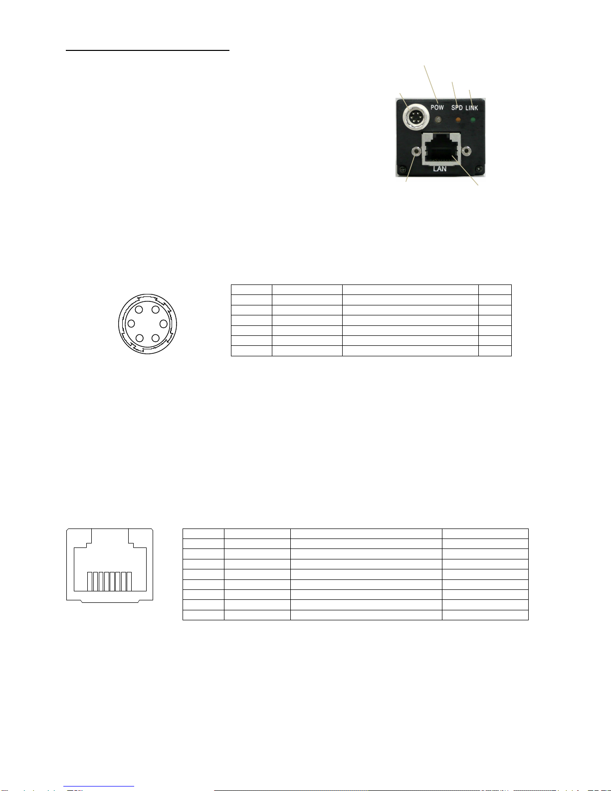
The Vinit signal is input from Pin (4) of the “CAMERA” connector (6 pin connector) on the rear of the camera.
(Note) Though the asynchronous trigger signal can be given by serial
communication command via GigE interface, it is not
suitable for real-time image capturing as it gets delayed
following packet forwarding.
(Note) When the camera is in OSD menu displaying status (when
the operation indicator LED blinks in green), periodic trigger
signal continues to be supplied from internal CPU so
that OSD display is updated on regular basis.
In this state, the external trigger signal (Vint) can not
be accepted.
Turn the OSD menu to hidden status to make Vint
signal input effective.
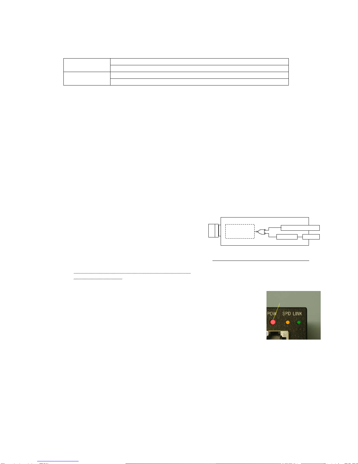
●LED Vinit signal monitor indicator
When this camera is set in the asynchronous shutter mode, the LED indicator on the rear
panel of the camera lights up in red for one shot in response to the input of the external
trigger signal (Vinit signal).
This allows the user to confirm the state of signal input.
The red LED lights up for a certain period of time (for about 100 ms) each time for a trailing
edge of the trigger input. If a following trigger signal is input within this period, the lighting
time of the LED will be retriggered and extended.
Since the lighting of the LED responses only to the trailing edge of the trigger input, it lights
up only once for 100 ms even if the trigger input pulse duration is longer than the one shot
time of period.
(Note) The external trigger signal (Vint) is not accepted when the camera is OSD
menu displaying status (when the operation indicator LED blinks in green).
(Note) Check again the connection status of Vint signal, input status of trigger signal and
the operation setting of the camera for any mistakes, if this monitor LED is not
properly displayed.
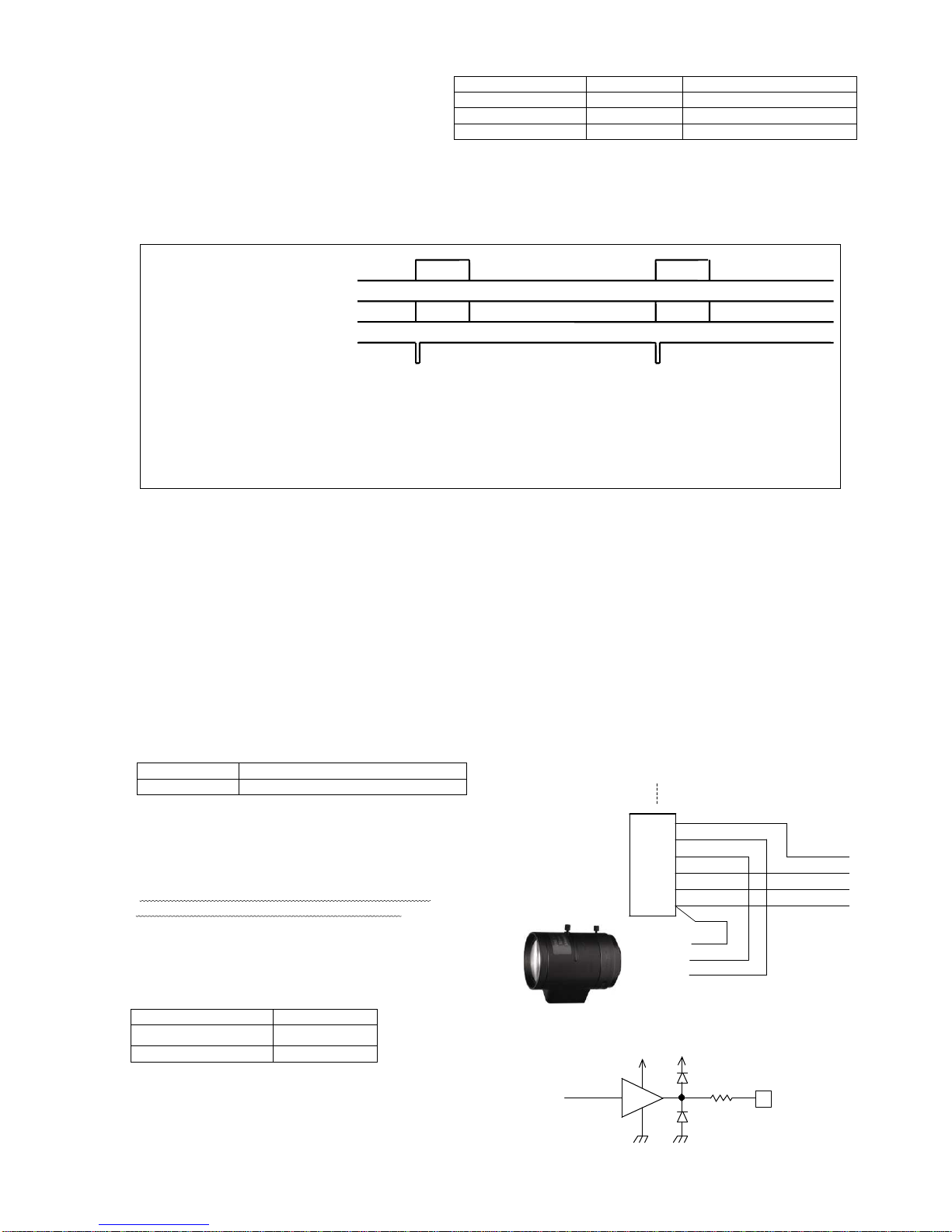
Fig. 4-2 Internal connection of Vinit signals
FCxxxGE
Internal circuit
Serial I/F
"POWER"- 4 (Vinit)
GigE
Red LED lights up in red in response
to trigger signal input (Vinit).
Lights up for one shot

M10510B;9/58
- 9 -
●
Recommended timing of asynchronous shutter trigger signal (Vinit signal) for preset shutter/pulse width control
For the case of preset shutter mode
, the negative logic pulse is
applied within the width range from 1 H (1 horizontal
synchronous interval) to 1ms as described below.
For this
case, the exposure operation starts in synchronization
with the
trailing edge of the internal HD pulse
(the leading edge
of pixel clock in the case of H-reset mode)
after and closest to
the trailing edge timing of the applied pulse.
For the case of the pulse width control exposure mode,
numeric value of
the L level interval of the input Vinit pulse
(shown as Tvinit in the figure) is retrieved in
synchronization with
the trailing edge of the internal HD pulse (the leading
edge of
pixel clock in the case of H-reset mode)
, and the integer multiple
number of H (1 horizontal synchronous interval
) that is closest to
the retrieved Vinit pulse duration is transmitted as nH
(the
integer multiple number of pixel clock in the case of H-
reset
mode) to the inside of the camera. Then the shutter speed
is
determined in response to the time nH.
Vinit
Tvinit
[For the case of preset shutter mode]
1H ≤Tvinit ≤1ms
(The exposure time is independent of the Vinit width.)
[For the case of pulse width control mode]
(Where PWC=ENABLED, shutter switch = 9)
nH ≤Tvinit <(n+1)H (n is 1 or larger integer.)
(This is the pulse width where shutter exposure time =nH)
Recommended Vinit signal timing waveform
(Note) In the pulse width control, the shutter exposure time is almost equal to the integral multiple number of the
horizontal synchronous time (H) that is closest to the Vinit pulse duration. More specifically, however, the
shutter exposure time is indefinite for the time period corresponding to 1H width in the case of normal external
trigger input (or the case where the Vinit signal is not in synchronization with the horizontal synchronous
timing of the camera). It is improved by being employed in “with H-reset” mode
→Refer to the timing chart described in another section for the details.
(Note) When the shutter exposure time is too long in the pulse width control mode, the S/N ratio of the image will
be degraded due to the reduction of dynamic range of CCD, accumulation of thermal noise components of
CCD image sensor in proportion to the shutter speed and other factors. Therefore, if a long exposure time is
employed, it is recommended to conduct experiments using realistic exposure times in actual conditions to
check for the appropriateness.
●Example of drive circuit for Vinit input circuit
* The Vinit signal should not include unnecessary noise components such as chattering.
[Input voltage range]
H level 2.5 to 5.5 V
L level -0.5 to 0.5 V
*
T
he voltage of the terminal end on camera side is required to be within the above voltage range with the camera being connected.
(4-4) Strobe signal (STRB)
It is able to adjust the light emitting timing of external strobe light to the exposure time of the camera.
This signal can be output in the continuous shutter mode as well as in the asynchronous shutter mode.
●Strobe signal output circuit
The signal output terminal is used both for strobe signal (STRB)
and busy (BUSY) signal.
Select any of OFF (Default: H level fixed), STRB and BUSY in
configuration setting.
→Refer to (7-5) Internal flag register and configuration register
The internal output circuit is shown in the right figure.
[output voltage range]
H level 3.0V (at 0mA) to 2.0 V (at 10mA)
L level 0.2V (at 0mA) to 0.5 V (at 10mA)
(!) The factory default is set to OFF for this camera.
It is required to set STRBC0 flag and STRBC1 flag when outputting STRB or BUSY signal,
+3.3V
100
5
STRB signal
TC7PA04FU
or equivalent
From
internal circuit
+3.3V
Camera
connector
75
Ω
4
Vinit1 IN
VCC
3.3 V
4.7k
47p
3.3 V
10k
100
Ω
TC7SH 14FU or equivalen t
To internal circuit
6.8V ZD
Trigger signal via serial communication
Trigger signal of internal CPU origin
VCC is +3.3V to +5V
74AC04 or
others
[Example of user circuit]
Inside of camera

M10510B;10/58
- 10 -
1
2
3
4
5
6
HR10A-7P-6P (Hirose)
6 pinconnector (male)
GND (0V)
IRIS
GND
Vinit
STRB
+12VDC
Videosignal
To
I
nput terminal of Auto iris lens
To connector
on rear of the camaera
To Power supply unit
12V DC
GND
●Output signal switching at strobe signal terminal
The signal from this terminal is set to OFF
as a factory default value.
This can be changed to STRB (Strobe timing
signal) or BUSY state by way of rewriting the
configuration register(CR) with serial
communication commands.
(CR5) and (CR6) correspond to STRBC0 and STRBC1, respectively.
●Strobe signal in continuous shutter mode
This equipment is capable of outputting the strobe signal even in the continuous shutter mode as well as in the
asynchronous shutter mode when the setting is changed to output the strobe timing signal(STRB).
[Explanation] Usage of strobe signal in continuous shutter mode
In the continuous shutter mode, only the incoming light for the time matching the exposure time of the camera is valid.
Accordingly, when a lighting unit is used in the continuous lighting mode, the lighting during the time other than this exposure time
period would be wasted.
Since this equipment is capable of outputting strobe signal (STRB) even in the continuous shutter mode, this output is used as a
trigger signal to control a LED light or other lighting units that can be turned on and off at high frequencies, which helps eliminating
the lighting during the useless lighting time.
The following benefits are derived from this type of lighting control:
●The consumption of the power to a light can be saved by way of lighting only during the valid time for exposure.
●The occurrence of smear is reduced because no light enters any time other than the exposure time periods.
(Note) When the strobe signal is used in the continuous shutter mode to make ON/OFF control on a lighting source unit,
the following must be taken into consideration:
Wherever possible, use a strobe lighting unit or others that are equipped with a power source separated from that
of the camera (electrically isolated power source) and a trigger input terminal (photo coupler input, etc.). If a
lighting unit that shares a power source or a ground circuit with the camera is turned on or off by the strobe signal,
the image output from the camera may have noise due to the influence of the fluctuation of the power supply
voltage or change in the electric potential that occurs at the ON/OFF timing.
Even when the insulation aforementioned is applied, the electromagnetic induction may lead to the occurrence of
noise on the image signal if the electric current of the lighting unit to be control is large. In this case, a measure
must be introduced to reduce electromagnetic induction noise arising from the lighting unit.
(4-5) Auto iris signal (IRIS)
●Connection method for Auto iris signal
This equipment has the function to output the signal for controlling the auto iris lens.
It can be used with the image signal input type-Auto iris lens being connected.
The specifications of the suitable auto iris lens are as follows.
Video signal 1.0Vp-p / High impedance input
Power input DC 12V / 60mA or less
(Note) ”IRIS” is the false image signal output exclusively
used for controlling the image signal input type-
Auto iris lens. It is not possible to take out
the normal image signal from this pin terminal.
(Note) Combined use of the Auto iris lens and AGC/AEC
function of this equipment is not permissible.
Turn the AGC/AEC setting OFF when connecting
Auto iris lens.
●Output circuit for Auto iris signal (IRIS)
This signal is effective as the Auto iris controlling signal
only in the case of no shutter mode or continuous shutter mode
Signal output level 0 to 0.7 V (DC)
Output impedance 75
Ω
Synchronizing signal None
(STRBC1,STRBC0)
Signal name Remarks
(0,0) OFF Always H level (Default)
(0,1) STRB Strobe timing
(1,0) BUSY Asynchronous shutter busy
Shutter exposure time
Continuous lighting
STRB signal
Exposure
Exposure
Valid Useless lighting time
A M P
3 . 3 V 3 . 3 V
IRISsignal
2
From
inbternalcircuit
75

M10510B;11/58
- 11 -
(4-6) Auto gain control function (AGC)
When AGC (Auto Gain Control) function is set to ON, the average value of the output signal is compared to the set reference
level (AGC set value), then the gain value of preamplifier on the stage prior to A/D converter is automatically controlled so that the
reference level and the average output value get equal .
The operating range of AGC is about 20dB.
Four functions below are limited to use in combination with AGC function.
Note that the combined use of them does not function well.
AEC function
Asynchronous shutter
Prolonged exposure
Auto iris lens
AGC function × × × ×
[Setup procedure]
●Set FR(15) and FR(14) as follows rewriting FR (Flag register) with serial communication software.
AGCE=FR(15)
AECE=FR(14)
AGC function 1 0
(Note) “AECE” (Auto Exposure Control Enable) needs to be set to “0”
●Adjust the AGC set value (Reference level) to get necessary luminance level.
(Note) S/N ratio of output signal degrades by using AGC function, in case that the amount of light is insufficient.
(4-7) Auto exposure control (AEC) function
Normal lens ( lens without auto iris function) can have an equal feature with an auto iris lens by using AEC function.
The average value of the output signal is compared to the set reference level (AGC set value), then the exposure time (electronic
shutter time) is automatically controlled so that the reference level and the average output value get equal .
When AEC function is set to ON, the camera enters Continuous shutter mode and the exposure time changes linearly by 1H
(Horizontal synchronous time) within the range of 1/1000 sec to No shutter.
Four functions below are limited to use in combination with AEC function.
Note that the combined use of them does not function well.
AGC function Asynchronous shutter
Partial scanning
Prolonged exposure
Auto iris lens
AEC function
× × × × ×
(Note) When AEC(Auto exposure control) is set to ON in No shutter mode, the camera automatically enters Continuous shutter
mode and the shutter time (exposure time) is automatically controlled in response to luminance.
(Note) When using AEC function, the picture level is subject to hunting phenomenon (phenomenon in which light-dark change
periodically occurs) for the image with the light source of which a brightness fluctuates.
Image output
to GigE I/F
CCD Preamplifier
GAIN
S/H
A/D
COMP
Compare
AGC set value
Gaincontrol
Block diagram
of AGCcontrol circuit
Image outpu
t
to GigE I/F
CCD Preamplifier
GAIN
S/H
A/D
COMP
Compare
AGC set valueMGC set value
Exposure time control
Block diagram of AEC control circuit

M10510B;12/58
- 12 -
Test pattern and horizontal profile
0
1020
[Setup procedure]
●Set FR(15) and FR(14) as follows rewriting FR (Flag register) with serial communication software.
AGCE=FR(15)
AECE=FR(14)
AEC function 0 1
(Note) “AGCE” (Auto Gain Control Enable) needs to be set to “0”
●Adjust the AGC set value (Reference level) to get necessary luminance level.
When the gain is insufficient, adjust the MGC set value a bit higher.
(Note) MGC set value is applied as the gain value of preamplifier on the stage prior to A/D converter.
S/N ratio of output signal degrades by setting MGC set value higher.
(4-8) Test pattern display function (Black and white data output)
When initially connecting this camera to an image capture board, the
use of the test pattern display function of the equipment makes it easier to
confirm that the output timing of the camera and the details of the signal
connection match the particulars of the capture board.
When the test pattern function is set to be ON, the image sensor outputs the
test pattern in place of pictures as shown on the right.
As for this pattern, a numerical value of 4 is simply added in an incremental
manner for every horizontal pixel, and a saw-tooth profile is shown in the range
from the numerical value of 0 to 1020.(When set at 10 bit output) (Lower part
of the right figure)
(Note) FS5000GE usually outputs RGB signals of Bayer arrangement CCD,
however output signal gets black and white data when using this
test pattern display function..
(Note) In terms of upper 8 bits in 10 bit data, this 8 bits data corresponds to the
data in which a numerical value of 1 is incrementally added for every
horizontal pixel in the range of 0 to 255.
The lower 2 bits in 10 bit data are fixed to 0.
Therefore, it is 0 to 1020 (only the lowermost bit and next bit are
0 ) in the 10 bit data range, and 0 to 4080 for the
case of 12 bit output.
(Note) The value does not start with 0 at the edge of the effective image area.
(Note) The output values of the test pattern are not affected by the values of the gain setting or offset setting of the
camera.
The default setting is OFF. This setting can be changed by way of rewriting the configuration register with serial
communication commands.
(4-9) Monitoring function for internal temperature of camera
This camera is equipped with an internal temperature sensor to monitor the temperature inside the body. This function
makes it possible to use the camera in a safer way even in a harsh environment in terms of temperature, for example use
in the open air. With the use of serial communication commands, this function also works to control the forced air-cooling
fan of the camera and peripheral devices and others.
●How to monitor internal temperature of camera
The following two methods are available for monitoring the internal temperature of the camera:
●Turn on the MENU display and confirm on the OSD over the image. (Temperature to be displayed in Celsius)
●Confirm with temperature data to be returned in response to the serial communication command (”RTMP”
command). (Numerical conversion required separately)
[Explanation] FR (15,14) setting and its operational mode
Correspondence relation of the content of each flag register FR(15),FR(14) and its operational mode is as follows.
AGCE=FR(15)
AECE=FR(14)
Operational mode Remarks
0 0 AGC=OFF, AEC=OFF
Factory Default
0 1 AEC=ON Auto Exposure Control valid
1 0 AGC=ON Auto Gain Control valid
1 1 Set inhibit Not use in this setting
※ Set contents of FR can be saved with respect to each program page by executing commands “WA” to “WF”
(Note) Refer to (7-5)” Internal flag register and configuration register”

M10510B;13/58
- 13 -
(Note) Carefully note that the temperature data obtained by this monitoring function is not for the ambient temperature but
the internal temperature of the camera. As a general rule, the internal temperature of the camera is higher than the
ambient temperature because of the heat generation associated with the consumed electric power inside the
camera.
Even when the temperature monitored by this function exceeds the value of the “Operation ambient temperature”
shown in the specifications of the camera, no operational trouble will be caused as long as the ambient
temperature is equal to the one of the specifications or lower, and sufficient countermeasures against temperature
are taken.
●Detection capability for temperature data
Minimum unit for temperature data : 0.5°
Data refreshing cycle : 0.4 sec.
Temperature detection accuracy: ±2°C (-40°C to +85° C), +3 to -2°C (55°C to 125°C)
Effective data range : -55°C to 125°C (as long as t he operation ambient temperature of the camera is
within the range defined by the specifications.)
●Temperature data by serial communication
The temperature data to be returned in response to the “RTMP” command of serial communication is generated in the
following format:
[Data format]
The lower 10 bits out of the 16 bits of the returned data are valid.
XXXXXD9D8…D0 (invalid upper 6 bits/valid lower 10 bits as the data)
Db=B’D9D8…D0 in the binary system shows a signed integer value in two’s complement form.
However, the effective range of the temperature data is limited to the following due to the operational restriction of the
temperature sensor:
Effective range of temperature data: -110 (-55°C) to +250 (125°C)
(Note) The accuracy of the values of the temperature data is not guaranteed when the operation ambient temperature is
not within the range defined by the specifications.
[Conversion method from returned data to temperature in Celsius]
The temperature in Celsius is computed as Tc from the following formula where Dt is the signed integer number converted
from the above described 10 bit binary value of “Db=B’D9D8…D0”:
Internal temperature of camera: Tc=Dt×0.5°C
(Example 1) Where Td, the returned value of the temperature data, is “H’0032” in the hexadecimal system, it is
expressed in the binary system as follows:
Td=H’0032=B’0000.0000.0011.0010
∴Db=B’00.0011.0010 =+50 (Only upper 10 digits of Td are valid.)
Then, Tc is calculated from the following formula: Tc=+50×0.5°C=+25°C
(Example 2) Where Td, the returned value of the temperature data, is “H’03FA” in the hexadecimal system, it is
expressed in the binary system as follows:
Td=H’03F1=B’0000.0011.1111.1010
∴Db=B’11.1111.1010 (Only upper 10 digits of Td are valid.) →Dt=-6 (↓Refer to [Explanation])
Then, Tc is calculated from the following formula: Tc=Dt×0.5°C=-6×0.5°C=-3°C
(4-10)Camera ID saving function
The ID code and other information set by the user for each camera can be stored in the camera and be read out when
needed. The saved identification data for each camera including installation location in the case of using more than one
camera (e.g., “CAMERA-RIGHT” and “CAMERA-LEFT”) allows the user to easily control and identify the camera (s).
The setting is executed through the serial communication. The settable maximum number of characters are 15, and
alphabets (both upper and lower cases), numbers and some special symbols such as”+” and “-” excluding the control
codes can be used.
(→Refer to the section of “Serial Communication Control” for the details.)
[Explanation] Example of conversion algorithm from data in the complement number system to signed data
The following example shows how to convert 10 digit data in the complement number system into ordinary signed data:
(1) Whether the value is positive or negative is determined by checking the uppermost bit (MSB) out of the 10 digit number. When the
MSB is 0, “+” is added, and when it is “1”, “-“ is added to the number (absolute value) to be obtained in accordance with the below
described (2).
(2) The absolute value is obtained from a binary number expressed in the remaining 9 digits including the lowermost bit (LSB) as follows:
Simply convert into an integer number if the MSB is 0 (”+” sign) in accordance with (1).
Reverse each of all the 9 digits and add 1 to the result if the MSB is 1 (“-“ sign) in accordance with (1).
(3) The signed number is obtained from (1) for the sign and (2) for the absolute value.
* In the case of the (Example 2) as above, its sign is “-“ because the MSB is 1 in accordance with (1). The absolute value is “6” because
of (invert(B'11111010)+ 1 = B'00000101 +1 = 5+1 =6) in accordance with (2). Therefore, this value (Dt) is expressed as “-6” in the
ordinary signed number system.

M10510B;14/58
- 14 -
Electronic shutter
operation mode
No shutter
operation
Electronic shutter
operation
Shutter
switch = 0
Shutter switch = 1 to9
Asynchronous shutter
low speed
shutter
High speed
shutter
Preset
shutter
Pulse width
control
Continuous shutter
High speed
shutter
Without
Fast
-
dump
With
Fast
-
dump
5. Various Settings
(!) This camera is not equipped with the substantial shutter setting switch on the rear panel. “Shutter switch” or “Mode switch”
described below means setting values of hypothetical shutter switch set on the memory inside the camera via serial
communication command.
→Refer to (5-8) for the specific setting method.
(5-1) Operation mode
●Electronic shutter operation mode
Shutter system
No shutter / continuous/asynchronous
Type of shutter speed
High speed / low speed/pulse width control
(See the right schematic diagram)
●Reset mode
It is able to select whether or not to reset the internal
horizontal synchronous timing (H) when in
asynchronous shutter mode.
Shutter system
Without H-reset / With H-reset
●Fast-dump·········Without Fast-dump / With Fast-dump
Table 5-1. Description of electronic shutter operation modes
Shutter
system No shutter Electronic shutter is not used.
Exposure time of image sensor is equivalent to one frame duration.
Exposure is continuously performed for each frame.
Continuous shutter Repeats exposure regardless of external trigger input (Vinit).
Repetition pitch is per frame.
Asynchronous
shutter Electronic shutter is released each time the external trigger is input (Vinit).
The shortest repetition pitch is [exposure time + 1 frame duration].
Type
of
shutter
speed
Normal shutter
(High speed shutter)
Shutter ,of which the exposure time is less than one frame, is used.
The shutter speed can be set as a preset shutter speed at 9 different
levels both for
the continuous shutter/asynchronous shutter operations.
Low speed shutter The shutter, of which the exposure time is two frames or over, is used.
(Only for continuous shutter mode) The shutter speed can be set as a preset shutter
speed at 9 different levels.
(Note) This camera allows this setting only for the continuous shutter mode.
Pulse width control Only in the case of asynchronous shutter setting, the shutter, of which shut
ter speed
corresponds to the pulse width (during L level) of the external trigger input (Vinit),
is
released.
Shutter speed can be set as nH (n = 1 or larger integer number)
in H (horizontal
synchronous time) unit.
Table 5-2. Description of other electronic shutter operation modes
Scanning
system Normal scan The read out for each frame is conducted by the all pixel readout scanning. (5Hz)
Partial scan The read out for each frame is conducted by the partial readout scanning.(10Hz)
The vertical width of the longitudinal picture area corresponds to approx. one-half of
the central portion of the image pickup area.
Fast-dump scan The read out in the midst of high speed/preset/asynchronous shutter operation is
conducted with high-speed fast-dump operation. The smear which appears in high
speed shutter operation is reduced only on the upper side above the image.
[Terminology] Preset shutter············This refers to the shutter speed setting other than those specified by the pulse width
control. More specifically, the shutter speed is set by the shutter switch positions
from “1” to “9” for the continuous shutter operation, or the shutter switch positions
from “1” to “9” (PWC (Pulse width control mode)=DISABLED) or from “1” to “8”
(PWC (Pulse width control mode)=ENABLE) for the asynchronous shutter operation.
The shutter speed is defined in the Table 5-3.
[Terminology] Pulse width control·····This is the way of setting and controlling of the shutter speed by the width of the Vinit
signal that is externally input in the asynchronous shutter mode. With this camera,
this is selected by setting PWC to “ENABLED” and the shutter switch position to “9”
in the asynchronous shutter mode.
[Terminology] High speed shutter·····This means the shutter of which shutter speed is shorter than 1 frame duration (=1
vertical synchronous time). The shutter speed is set as a preset fixed length of the 9
different levels that are determined by the position of the shutter switch (continuous
shutter and asynchronous shutter).
[Terminology] Low speed shutter······This means the shutter of which shutter speed is longer than 1 frame duration. The
shutter speed is set as a preset fixed length of the 9 different levels that are
determined by the position of the shutter switch (continuous shutter).

M10510B;15/58
- 15 -
[Terminology] Fast-dump mode…. The effect of smear which appears in capturing images of high-intensity object can
be reduced only for the upper side above the image by quickly dumping (sweeping
out) unnecessary charges in the transfer channel of the CCD imaging device right
after the trigger pulse is input in the asynchronous shutter operation.(one sided
smear behavior)
Exposure starting time is delayed for the dumping time (82H=approx.8ms), if the
Fast-dump is selected.
(!) This camera does not support the functions of “low speed/asynchronous shutter”.
[Explanation]
Fast-dump operation is effective in the preset/high speed/asynchronous shutter mode.
In case of the infra-ray-emitting high-intensity object, it often happens by the nature of CCD sensor that
even the low intensity part is displayed whitely like a vertical streak above and below the high-intensity
object by reason that the generated charges leak into the transfer channel of CCD sensor even outside
of exposure time.
This phenomenon is called“smear”. Shorter the exposure time gets, higher the relative ratio of
brightness against the normal Image part becomes, and it poses impediment for image processing.
This camera is equipped with “Fast-dump function”in the asynchronous shutter operation
as standard and this contributes to reduction of smear (especially for the smear extending upward
of the image). Exposure starting time is delayed for the dumping time, if the high-speed dump is
selected.
Without Fast-dump With Fast-dump

M10510B;16/58
- 16 -
(5-2) Setting of shutter speed
The shutter speed is determined by assigning “0 - 9” to the shutter switch position or specifying the shutter speed in H
(Horizontal scan time) unit.
As this camera is not equipped with the substantive shutter setting switch, the shutter speed is specified by changing the
Feature settings regarding the exposure time of GenICam API or using the serial communication command via serial
communication software.
The shutter speed setting is mainly decided by setting position “0” to ”9” of (Hypothetical) shutter switch.
●Correspondence relation between Shutter speed and shutter switch setting
Table 5-2 Setting value of shutter speed
Shutter speed
Position of
shutter switch
High speed shutter
(continuous/asynchronous) Low speed shutter
(continuous)
0 No shutter (continuous) 1/5 second (2056H=1V)
1 1/8600 second (1H) 1/2.50 second (2V)
2 1/3000 second ( 3H) 1/1.67second (3V)
3 1/1200 second (8H) 1/1.25 second (4V)
4 1/600 second (17H) 1/1.00 second (5V)
5 1/240 second (43H) 1/0.83second (6V)
6 1/120 second (86H) 1/0.71 second (7V)
7 1/60 second (171H) 1/0.63 second (8V)
8 1/30 second (343H) 1/0.56 second (9V)
9 1/15 second (686H) Pulse width control
/asynchronous (!) 1/0.50 second (10V)
(Note) (H) and (V) in the table represent the horizontal time unit and the vertical time (frame duration) unit respectively.
(Note) ”No shutter” in the table means the continuous shutter mode with exposure time = 1 frame duration.
(Note) The value of the each shutter speed is the factory default value. The shutter speed of each position (excluding
shutter position = 0) is possible to change by the user with serial communication command.
(!) As for this camera, “Pulse width control time/asynchronous” must be set to be “Pulse width control (PWC) =
ENABLED”.
When it is set to be “Pulse width control (PWC) = DISABLED” (default), the selection can be made out of the 9 levels
not only for the continuous shutter operation but also for the asynchronous shutter operation.
(!)
“Shutter switch” means the hypothetical shutter switch set on the memory inside the camera via serial communication
command.
[Explanation]
The shutter speed is specified by reading out the value on the electronic shutter table (separately exist on page A to F )
corresponding to the set position of shutter switch.(excluding directly designated value )
The electronic shutter table can all be rewritten with the serial command “E” (shutter table Edit command) except shutter switch ”0”..

M10510B;17/58
- 17 -
(5-3) Level setting
The level setting is mostly divided into the
following two groups:
●Gain setting
This is to set the gain (amplification factor)
of the preamplifier between the CCD image
sensor inside the camera and A/D converter.
●Offset setting
This is to set the offset value of the
preamplifier between the CCD image sensor
inside the camera and A/D converter.
→Refer to the next section (Section 6) for
the specific setting method.
(Note) As for the offset setting, it is
recommended to use the factory
default value except for a special case.
(Note) Follow the procedure (gain setting
followed by offset setting) if fine tuning
of the offset value is needed.
(5-4) Gain setting of preamplifier
●Gain variable amplifier and integrated gain
The image signal output from CCD is amplified inside the
camera through the fixed gain amplifier on the anterior
stage and then through the following variable gain amplifier
before being input into the A/D converter.
The left block chart shows this flow.
(Note) The gain value (dB) described here is the one based on
the CCD output (0 dB) as the baseline.
●Correlation between MGC gain setting value and MGC gain
The MGC setting value of this equipment is controlled
by giving 0 to 255.
The correlation between this setting value and the
MGC gain (integrated gain including the gain of the
variable gain amplifier and that of the fixed gain
amplifier) is shown in the right graph.
(Note) When the CCD element receives excessive light
with a low gain value of the amplifier due to the
restriction of the dynamic range of the CCD light
receiving element, the signals of the nonlinear
area of the CCD element and the preamplifier
are output at the high brightness area.
In this state, unnatural image (Note below) may
appear in the neighborhood of the saturating
signal area of the image due to the
characteristic of the nonlinear area. This
phenomenon, which is associated with the
saturation characteristic of the CCD element, is
not a failure arising from the camera.
To eliminate this phenomenon, reduce the
amount of light by stopping down the lens and
newly set a higher gain value. Then, the output
signal from the CCD element at the saturating
area will be appropriately saturated into a white
level for the output.
Signal level
Time
Time
Time
1 0 2 3
0
0
1 0 2 3
0
Increase in OFFSET
Increase in GAIN
Image signal
1 0 2 3
(Befor setting
adjustment
)
Conceptual diagram of gain and offset levels
Signal level
Signal level
CCD
Preamplifier
A/D
GAIN
Variable gainamplifier
5.1dB
~
32.6dB
Integratedgain
MGCsetting
Fixedgain amplifier
6dB Fixed 11.1dB
~
38.6dB
42
36
30
24
18
12
6
0 64 128 192 (255)
MGCGAIN CODE
MGC GAIN (dB)

M10510B;18/58
- 18 -
Program page F
Program pages from B to E
Program page A
[Electronic shutter operation mode]
•Shutter system = Continuous/asynchronous
•Type of shutter speed = Highspeed/ low speed
•Electronic shutter table =
Correspondence
relation b/w shutter switch position and
shutter speed
• Pulse width control = Enable / Disable
[Level setting]
•Gain setting value = (Saved as the internal value)
•Offset = (Saved as the internal value)
[Other operation modes]
•Gain mode = MGC /AGC
Andothers
Conceptual diagram of program page
(Note) The above described unnatural image
represents the following states:
●
Black and white look inverted at the saturating area.
●
The outline of the saturating area is blurred.
●
The saturating area slightly shifts upward or downward.
●
The brightness of the saturating area does not reach 1023.
(5-5) AGC gain setting
AGC function turns on by setting AGCE(AGC Enable) bit in flag register(FR) to 1.
The operating range of AGC is about 20dB.
(Note) AGC setting and MGC setting are incompatible with each other.
(5-6) Output data bit format setting
Three formats below are selectable as the data format outputting with
Camera Link interface,.
8 bit Gray scale (Default)
10 bit Gray scale
12 bit Gray scale
This camera is equipped with A/D converter with 14 bit output.
8 bit to 12 bit data of the upper bits of A/D converter is output in accordance
with output format setting as the right table.
The setting is changed by rewriting (CR)(Configuration register) with serial
communication command.
(5-7) Program page setting
The FC series cameras are internally equipped with nonvolatile memories
and various operation mode settings and level settings can be stored in them.
The setting items are stored in the virtual pages (hereinafter referred to as
“program pages” inside the camera.
This camera has 6 program pages of “A”, “B”, “C”, “D”, “E” and “F” (right
figure).
The camera starts operating according to the various settings stored in the
relevant page when the mode switch is at any one of the positions from “A” to
“F” at the time of power-on.
(!) As this camera is not equipped with the substantial shutter setting switch
on the rear panel, “Mode switch” described here means setting values of
hypothetical mode switch set on the memory inside the camera.
The position of this (hypothetical) mode switch can be set, read and
saved with serial communication command.
(Note) The memory has the configuration area aside from the saving area
of the program pages that is independent from the program pages.
The common setting items (Configuration items) are saved on this area.
(5-8) Setting of Shutter switch and Mode switch
This camera is not equipped with the substantial shutter switch and mode switch. The hypothetical switches set on the memory
inside the camera are used as a substitute for these switches.
The set values of these switches are stored in nonvolatile ROM and these values are read out onto RAM at the time of power-on.
(5-8-1) Confirmation of set position of Shutter switch and Mode switch
It can be confirmed by any of the following methods.
●
Confirmation on the OSD menu screen
Current setting status of Mode switch (MS) and Shutter switch (SW) can be
confirmed by displaying the OSD menu on the captured image.
MS
・・・・
Set value of Mode switch
SS
・・・・
Set value of Shutter switch
→
Mode switch is set to Aand Shutter switch is set to 2 on the right example.
Image data Assignment of Output data
(A/D output)
12 bit 10 bit 8 bit
AD13 D11 D9 D7
AD12 D10 D8 D6
AD11 D9 D7 D5
AD10 D8 D6 D4
AD9 D7 D5 D3
AD8 D6 D4 D2
AD7 D5 D3 D1
AD6 D4 D2 D0
AD5 D3 D1 -
AD4 D2 D0 -
AD3 D1 - -
AD2 D0 - -
AD1 - - -
AD0 - - -
(Default)

M10510B;19/58
- 19 -
●
Confirmation by GenICam feature
It can be confirmed by GenICam feature as below when using the application software like GEVPlayer (that comes with
attached SDK) which can set up and read out the GenICam feature.
TakexCameraControls > FcModeSW
・・・
Feature of Mode switch setting
TakexCameraControls > FcShutterSW
・・・
Feature of Shutter switch setting
●
Confirmation by Serial communication command
The current setting values of Shutter switch and Mode switch can be confirmed by using the following commands when the
communication with serial communication commands is possible using Coyote and FCTool (that comes with attached SDK) or
others.
Command ”RMSW”
・・・
To read out the current set values of Mode switch
Command ”RSSW”
・・・
To read out the current set values of Shutter switch
(5-8-2) Mode switch and Shutter switch settings change
It can change settings by any of the following methods.
●
Setting by GenICam feature
It can be changed by changing GenICam feature settings as below when using the application software like GEVPlayer (that
comes with attached SDK) which can set up and read out the GenICam feature.
TakexCameraControls > FcModeSW
・・・
Feature of Mode switch setting
TakexCameraControls > FcShutterSW
・・・
Feature of Shutter switch setting
●
Setting by Serial communication command
The current setting values of Shutter switch and Mode switch can be changed by using the following commands when the
communication with serial communication commands is possible using Coyote and FCTool (that comes with attached SDK) or
others.
Command ”WMSW”
・・・
To write the set values of Mode switch
Command ”WSSW”
・・・
To write the set values of Shutter switch
(Note) Refer to section 6-3 for the details about setting and reading of the GenICam feature.
(Note) Refer to section 7-2 and 7-3 for the details about confirmation and setting by serial communication command.

M10510B;20/58
- 20 -
6. Operation by Image display software
Operation examples for changing camera settings using Image display demonstration software in attached SDK (Software
development kit) are described in this section
→
Refer to “FC-GE series camera Instruction manual (Connection edition)” of separate volume for the details about the installing
method of SDK or the specific procedure for executing image display with the camera being connected to PC.
(6-1) Image display software in attached SDK
Image display demonstration software “GEVPlayer”(eBUS-PureGEV Packge) and ”COyote”(eBUS-Vision Package) become
available by connecting the camera to PC via Ethernet and by installing attached SDK (“eBUS-PureGEV Packge” and ”
eBUS-Vision Package”).
It can display the image on PC monitor and can save the image data using these Image display demonstration software.
→
Refer to “FC-GE series camera Instruction manual (Connection edition)” of separate volume for the details about the installing
procedure and the usage of these display software (“GEVPlayer” and ”COyote”).
<GEVPlayer Display screen>
<Coyote Display screen>
[Important] Regarding SDK selection at the time of development of application software
This equipment adopts the Pleora (Canada)’s iPORT as IP engine.
“eBUS-PureGEV Packge“(GenCam API-compliant development environment) and “eBUS-Vision Package”(non-GenCam API-compliant)
are available as SDK in iPORT.
Although “eBUS-Vision Package” including demonstration display software “Coyote” has been used for many years, Pleora strongly
recommends to use “eBUS-PureGEV Packge“(GenICam API-compliant development environment), as a trend shifting to GenICam
API-compliant cameras becomes more common among third-party image processing software makers and many GigE camera makers.
Except for particular reasons that iPORT interface or application software has been developed for years on the platform of Pleora’s
“eBUS-Vision Package”, we recommend to develop the new application software using “eBUS-PureGEV Packge“ that is the GenICam
API-compliant development environment.
This manual suits for next models
2
Table of contents
Other Takenaka System Security Camera manuals