Takenaka System FS2300DV User manual

N11A27;1/37
- 1 -
Video Camera
Instruction Manual
2 Mega pixel Progressive Scan Color Camera
FS2300DV
●We greatly appreciate your confidence choosing our TAKEX CCD Video Camera.
●Please read this manual and the attached guarantee certificate carefullyand manage the camera properly.
Keep this manual at hand and reread it whenever you are uncertain about the operation.
Table of Contents
1. Features ………………………………………………… 3
2. Outline ………………………………………………… 3
3. Description of each component ………………………………………………… 4
4. How to operate ………………………………………………… 6
5. Various settings ………………………………………………… 12
6. How to change settings ………………………………………………… 16
7. Serial communication control ………………………………………………… 25
8. Timing chart ………………………………………………… 29
9. Notes ……………………………………………… 35
10. Specifications ………………………………………………… 36
11. Dimensions ………………………………………………… 37
TAKENAKASYSTEM CO., LTD.
Document No. N11A27
FS2300DV Instruction Manual (3
rd
Version)

N11A27;2/37
- 2 -
[Revision history]
Version Revised contents Articles Date
Document
No.
Remarks
1 1
st
version -- Initial version 2010-07-16
N10601 FS2300DV
2 2
nd
version
Error correction 2011-06-21
N11311A
3.
3
rd
version Error correction 2011-10-27
N11A27
Description of special remarks used in this manual
(Note)················ Particulars which require the user’s attention are explained.
(!)················ Particulars which require the user’s close attention in terms of comparison with the conventional
products are explained.
[Terminology]················ Terms specifically defined for the purpose of describing the operation of this camera are
explained.
[Explanation]················Particulars for which details may be needed for user’s understanding of the operation of this
camera are explained.

N11A27;3/37
- 3 -
1. Features
●
FS2300DV is a full frame shutter color camera incorporated with 2.01 megapixel, 1/1.8”-size CCD image sensor.
●
Afull frame shutter image can be obtained at a rate of 20 frames per second.
●
The RGB 8 bit digital image signal output complying with Camera Link (Base Configuration).
●
Digital image signal can be displayed on the DVI monitor at high resolution.
●
Four line cursors can be displayed on the monitor at a time.(cross, grid and boxare selectable)
●
The internal set values of the camera can be externallycontrolled with serial communication via Camera Link.
●
The character information of the current setting status of the camera can be superimposed over the captured image on
the screen. (On Screen Displayfunction)
●
The monitoring function for measuring the internal temperature of the camera.
●
The asynchronous shutter is applicable both in the preset shutter mode and the pulse width control mode.
2. Outline
Image sensor
Sensor size
Effective pixels
Pixel size
Progressive scanning, Interline transfer
OB (Op tica l b lack )
2
1 6 28
48
1
0
Effective image pickup area
H
V
123 6
12
(1220)
(1 6 20 )
8
4
G b B G b
R G r R
R G r R
1/1.8 inch
1628(H) × 1236(V) 2.01 megapixels
4.4μm(H) × 4.4μm(V)
Read out
scanning
Horizontal 25.0 kHz
Vertical 20.0 Hz
Clock 48.10 MHz
Electronic shutter 1/16000 to 1/20 sec.
(Continuous shutter /Asynchronous shutter)
Video output signal
Digital RGB 8bit
Bayer 10bit,8bit,12bit
Complied with Camera Link (Base Configuration)
Scanning mode Normal scanning for all pixels (20fps)
Monitor output
1920(H)×1080(V) 60Hz
(Reduced Blanking)
Displaying area 1600(H)×1080(V)
Block diagram
Spectral sensitivity
CCD
A/D
OFFSET
RGB8bit
P re am pl ifi er
GAIN
UART
S/H
Vinit
RXD
TXD
STRB
D RIV E R
FPGA
SYNC etc.
Analog front-end
Camera Link
connector
Camera L ink
Base Configration
Ch annel Link
CLK,HSYNC,VSYN C
Vinit1
T.M.D.S
Transmitter
HDMIconnector
RGB8bit
T.M.D.S
CLK,LDV,FDV
1.0
0.9
0.8
0.7
0.6
0.5
0.4
0.3
0.2
0.1
0.0
R
e
l
a
t
i
v
e
s
e
n
s
i
t
i
v
i
t
y
400
Wavelength
(nm)
(Typical value)
500 600 700450 550 650
B G R
G b B Gb B
G b B Gb B
R G r R G r
Horizontal direction
Vertical direction
RG r R G r
●
FS2300DV is equipped with a primary
color CCD as a image sensor.
Color coding
The Bayer color filter array is adopted
for a RGB primary color filter
arrangement.(See diagram below)
Gb or Gr in the diagram represents
Green filter on the same line as Blue
filter or Red filter respectively.
Note : The characteristics of lens, luminous source
or others are left out of consideration.

N11A27;4/37
- 4 -
3. Description of Each Component
(3-1) Description of rear panel of camera
Panel to set up operation mode, electronic shutter speed and
other parameters and to connect each output connector
(3-2) Camera connector (HRS HR10A-7R-6PB)
The pin arrangement of the camera cable connector (6 pins) and
the signals assigned to those pins are shown in the following table:
6
5
43
2
1
(Pin arrangement viewed from
the outside of the camera)
Pin No. Signal name Description I/O
1 GND (0V) Power ground
2 IC Reserved for future product (In)
3 GND Signal ground
4 Vinit1 Input for external trigger In
5 STRB Strobe signal output Out
6 +12VDC DC power input (In)
* Do not assign any signals to the IC pins ,as those are used inside the camera.
(3-3) Camera Link connector (3M / SDR-26 FEMALE)
The pin arrangement and the signals assigned to those pins are shown in the following table:
[Pin arrangement of Camera Link connector (SDR-26 Connector)]
Pin No.
Signal name Twin-ax cable
assignment Pin No.
Signal name
Twin-ax cable
assignment
1
inner shield
shield
14
inner shield
shield
2
X0
-
PAIR1
-
15
X0+
PAIR1+
3
X1
-
PAIR2
-
16
X1+
PAIR2+
4
X2
-
PAIR3
-
17
X2+
PAIR3+
5
Xclk
-
PAIR4
-
18
Xclk+
PAIR4+
6
X3
-
PAIR5
-
19
X3+
PAIR5+
7
SerTC+
PAIR6+
20
SerTC
-
PAIR6
-
8
SerTFG
-
PAI
R7
-
21
SerTFG+
PAIR7+
9
CC1
-
PAIR8
-
22
CC1+
PAIR8+
10
CC2+
PAIR9+
23
CC2
-
PAIR9
-
11
CC3
-
PAIR10
-
24
CC3+
PAIR10+
12
CC4+
PAIR11+
25
CC4
-
PAIR11
-
13
inner shield
shield
26
inner shield
shield
2
6
1
3
1
4
1
Camera Link
External view of Camera Link connector
(Viewed from the outside of the camera)
(Note) The pins of Camera Link connector are differently laid out for the
camera (upper table) and for the capture board.
Note that the connection numbers of the cable for the capture board
are opposite to those for the camera as described below:
1 = inner shield, 14 = inner shield
2 = CC4-, 15 = CC4+
3 = CC3+, 16 = CC3-
⋅⋅⋅⋅ ⋅⋅⋅
12 = X0+, 25 = X0-
13 = inner shield, 26 = inner shield
(Pin layout on frame grabber board side)
Camera Link
connector
Camera connector
(6 pin)
C am e r a L i nk
POWER
Operation
indicator(LED)
HDMI connector
for DVI output
DVI

N11A27;5/37
- 5 -
[Table of Camera Link bit assignment] (showing correspondence relation between before andafter encoding)
Camera Link port
(Node name) Camera signal
name I/O
Remark
Strobe
CLK
O
Pixel clock
LVAL
LDV
O
Horizontal synchronous timing
FVAL
FDV
O
Vertical synchronous timing
DVAL
-
O
(Fixed to H level)
Spare
-
O
(Fixed to H level)
RGB
8 BIT OUTPUT
PORTA0 / PORTB0 / PORTC0
D0
0
O
Red/Green/Blue
Lowermost data
PORTA1 / PORTB1 / PORTC1
D0
1
O
PORTA2 / PORTB2 / PORTC2
D0
2
O
PORTA3 / PORTB3 / PORTC3
D0
3
O
PORTA4 / PORTB4 / PORTC4
D0
4
O
PORTA5 / PORTB5 / PORTC5
D0
5
O
PORTA6 / PORTB6 / PORTC6
D0
6
O
PORTA7 / PORTB7 / PORTC7
D0
7
O
Red/Green/Blue
Upper
most data
BAYER
10 BIT OUTPUT
PORTA0 / PORTC0
D0
0
O
Lowermost data
PORTA1 / PORTC1
D0
1
O
PORTA2 / PORTC2
D0
2
O
PORTA3 / PORTC3
D0
3
O
PORTA4 / PORTC4
D0
4
O
PORTA5 / PORTC5
D0
5
O
PORTA6 / PORTC6
D0
6
O
PORTA7 / PORTC7
D0
7
O
PORTB0 / PORTB4
D08
O
PORTB1 / PORTB5
D09
O
Upper
most data
PORTB2,3,6,7
-
O
(Fixed to
L
level)
CC1
Vinit2
I
Asynchronous shutter
trigger
CC2
(reserved)
I
(Reserved for future products)
CC3
(reserved)
I
(Reserved for future products)
CC4
(reserved)
I
(Reserved for future products)
SerTFG
TXD
O
URAT transmission data (Same timing as conventional RS
-
232C)
SerTC
RXD
I
URAT receptio
n data (Same timing as conventional RS
-
232C)
* The port assignment is in conformity to “Base Configuration”, the standard of Camera Link.
External view of Camera Link cable assembly
Fixing screw× 2
Fixing screw× 2
MDR-26 Twin-Ax cableharness (male)
SDR-26 Twin-Ax cable harness (male)
Twin- Ax cable

N11A27;6/37
- 6 -
(3-4) DVI-D output,HDMI connector
(Note) Pin 17(+5V) are monitor wiring pins. Do not
use of them for the purpose other than that.
(Note) This camera has DVI-D output. Images may
not displayed when connected to HDMI input.
(Note) Use the 1920×1080 ,60Hz(RB)- conforming
multiscan monitor , otherwise images may not be displayed on the monitor.
4. How to Operate
(4-1) Connection method
●Connection
Refer to the connection example between the camera and peripheral devices (Fig. 4-1).
(1) Remove the cover of the lens attachment section and
attach a lens (separately sold).
(2) Connect the camera to a power supply unit
(separately sold) with a camera cable (separately
sold). The maximum allowable length of a camera
cable is 15 m.
(3) Set the camera operation modes in accordance with
the setting instructions for the operation modes and
the shutter speed that are described in another
section.
(4) When the digital output on the rear panel of the
camera is used, connect the digital output connectors
and the input terminals of the image processing units
(frame grabber board, computer, etc.) with digital
cables (separately sold) conforming to Camera Link.
The maximum allowable length between the digital
output connector of the camera and the input terminal
of said image processing unit is 10m.
(5)When the DVI-D output on the rear panel of the camera is used, connect the DVI-D output connector (HDMI shape) and
the 1920
×
1080 ,60Hz(RB) -conforming multiscan monitor with the DVI-D - HDMI conversion cable. The maximum
allowable length between the DVI-D output connector of the camera and the multiscan monitor is 5m.
(6) Confirm the connecting condition before turning on the power switch of the camera.
In 1 or 2 seconds after the power is turned on, the LED operation indicator on the rear panel of the camera changes
from orange to green to showthat the camera is in operation.
(Note)The maximum allowable lengths of the camera cable and the digital cable aforementioned are not for the purpose of
guaranteeing the operation of the camera. Proper image signals may not be obtained even when the cables are
within the allowable ranges, depending on the installation conditions ofthe camera, types ofcables in use and others.
Pin No.
DVI signal name Pin No.
DVI signal name
1 TMDS DATA2+ 11 TMDS DATA CLK shield
2 TMDS DATA2 shield 12 TMDS DATACLK-
3 TMDS DATA2- 13 N.C
4 TMDS DATA1+ 14 N.C
5 TMDS DATA 1 shield 15 DDC/SCL
6 TMDS DATA1- 16 DDC/SDA
7 TMDS DATA0+ 17 GND (monitor)
8 TMDS DATA 0 shield 18 +5V (monitor)
9 TMDS DATA0- 19 HOT Plug Detect
10 TMDS DATACLK+ - -
1 8
19 1
External view of
HDMI
connector
(Viewed fromtheoutside of the camera)
D V I
2
Computer
Captureboard
(Camera Link)
PO W E R
O N
L O CK
C Y C L
DIRECT
T R I G
P U 100
PO WER U NIT
Pulse generating
circuit
(
sensor and others
)
T R IG
Cameracable
6P12Getc.
Camera Link cable
PU100
(
or PU120
)
FC camera
F C - C A M
DVI-HDMI conversioncable
19 20 × 10 80
Fig. 4-1 Connection example between camera
and peripheral devices

N11A27;7/37
- 7 -
[Important]
(Note) Make sure to turn off the power switch of the camera before connecting or disconnecting the camera cable.
If the cable is connected or disconnected while the power is supplied, it may cause the camera troubles.
(Note) Make sure to turn off the camera and connected devices in advance before connecting the camera.
(Note) When a power supply unit other than Takenaka’s product that are separately sold is used, make sure that it complies
with the following rated specifications:
Power supply voltage: DC12V±10%
Current capacity: 400mAor over
Take into consideration the fact that inrush current of about 1Aflows in when power is applied.
Ripple voltage: 50mVp-p or less (recommended value)
Connector: 6 pin connector pin 1 (GND), pin 6 (+12VDC)
(Note) Some power supply units other than TAKENAKA’s products have different layout of power connection pins. Make sure
to check the compatibility of the power supply unit and the camera connection pins in advance.
Carefully note that any failure associated with power application to out-of-specification pins and others is subject to
charged repair.
(4-2) Input of Vinit signal (asynchronous trigger signal)
●How to input Vinit signal
If the camera is used in the asynchronous shutter mode, the Vinit signal (asynchronous trigger signal) must be input
from the user side unit.
The Vinit signal is input from Pin (4) of the “POWER” connector (6 pin connector) on the rear of the camera, or is input
as the CC1 signal from the “Camera Link” connector.
If the camera is connected to the power supply unit PU100 (or PU-97), with a Takenaka’s 12W series cable, connect
the Vinit signal (asynchronous trigger signal) to the trigger input terminal (“EXT” BNC in case of PU-97) of the power
supply unit (PU100).
(Note) OR operation (negative OR) is implemented inside the camera between Vinit1 input signal from Pin (4) of “POWER”
connector and Vinit2 input signal as CC1 signal of “Camera Link” connector (see thefigure below).
(Note) If either one of those are fixed to the L level (active state),
the Vinit signal (logical sum) is also fixed to the L level and
the trailing edge signal cannot be obtained. This would
result in failure in starting up the asynchronous shutter
operation. Make sure to fix the input signal on the unused
side to the H level or to keep it at high impedance level or
open state (no connection).
●LED Vinit signal monitor indicator
When this camera is set in the asynchronous shutter mode, the LED
indicator on the rear panel of the camera lights up in red for one shot
in response to the input of the external trigger signal (Vinit signal).
This allows the user to confirm the state of signal input.
The red LED lights up for a certain period of time (about 100 ms) on
each trailing edge of the trigger input pulse. If a next trigger signal is
input within this period, the lighting time of the LED will be retriggered
and extended.
Since the lighting of the LED responses only to the trailing edge of the
trigger input, it lights up only once for 100 ms even if the trigger input
pulse duration is longer than the one shot time of period.
LED operation
indicator
Red LED lights up in response to trigger
signal input (Vinit).
"CC1” (Vinit 2)
H
"POWER” - 4 (Vinit 1)
Internal
circuit
Fig. 4-2 Internal connection of Vinit signals
FC_CLcamera
C am e r a L i nk
POWER
DVI

N11A27;8/37
- 8 -
●Recommended timing of asynchronous shutter
trigger signal (Vinit signal) for preset shutter/pulse width control
For the case of preset shutter mode
, the negative logic pulse is
applied within the width range from 1 H (one
horizontal
synchronous time) to 1ms as described below.
For this case, the
exposure operation starts in synchronization with the trailing
edge (the leading edge of pixel clock in the case of H-
reset
mode) of the internal HD pulse (horizontal synchronous signal)
after and closest to the trailing edge timing of the applied pulse.
For the case of the pulse width control exposure mode, numeric
value of the L level interval of the input Vinit pulse (shown as
Tvinit in the figure) is retrieved in synchronization with the trailing
edge of the
internal HD pulse (the leading edge of pixel clock in
the case of H-
reset mode), and the integer multiple number of H
(one
horizontal synchronous interval) that is closest to the
retrieved Vinit pulse duration is transmitted as nH (the integer
multiple number of pixel clock in the case of H-
reset mode) to
the inside of the camera. Then the shutter speed is determined
in response to the time nH.
Vinit
Tvinit
[For the case of preset shutter mode]
1H(horizontal scan time)≤Tvinit ≤1ms
(Theshutter exposure time is independent of the Vinit width.)
[For the case of pulse width control mode]
nH ≤Tvinit <(n+1)H (n is 1 or larger integer.)
(This isthe pulse width where shutter exposuretime =nH)
Fig. 4-3 Recommended Vinit signal timing waveform
(Note) In the pulse width control mode (without H-reset), the shutter exposure time is almost equal to the integral
multiple number of the horizontal synchronous time (H) that is closest to the Vinit pulse duration. More
specifically, however, the shutter exposure time is indefinite for the time period corresponding to 1H width in
the case of normal external trigger input (i.e. the case where the Vinit signal is not in synchronization with the
horizontal synchronous timing of the camera). It is improved by being employed in “with H-reset” mode
→Refer to the timing chart described in another section for the details.
(Note) When the shutter exposure time is very long (i.e. longer than one vertical synchronous time) in the pulse
width control mode, the S/N ratio of the image will be degraded due to the reduction of dynamic range of CCD
by the accumulation of thermal noise components of CCD image sensor in proportion to the shutter speed
and other factors. Therefore, if a long exposure time is employed, it is recommended to conduct experiments
using realistic exposure times in actual conditions to check for the appropriateness.
●Example of drive circuit for Vinit1 input circuit
75Ω
4
Vinit1 IN
VCC
3.3V
4.7k
47p
3.3V
10k
100Ω
NORMAL
INVERTED
6.8V
* The Vinit signal should not include unnecessary
noise components such as chattering.
●Polarity reversal of Vinit2 input
The input polarity of the triggersignal (Vinit2) to be applied via CC1 of Camera Link can be inverted.
Some capture boards may have the polarity of the trigger signal input from CC1 that is fixed to positive logic (Llevel at
normal / H level at active), which is not compatible with the trigger signal of negative logic input (factory preset polarity
of this equipment). In this case, the input polarity of the trigger signal (Vinit2) via CC1 can be inverted to change from
negative to positive logic by the setting of the camera.
→Refer to “(6-3) How to set operation mode” for the specific setting method.
(Note) The setting of the polarity reversal is valid only for Vinit2. The input polarity of Vinit1 is always negative logic
regardless of this setting.
74AC04 or
others
Inside of camera
TC74LVX14
(or equivalent)
To internal circuit
Setting of Vinit2 polarity
CC1 (Vinit2) input
Camera
connector
VCC is +5V or +3V
[Example of user circuit]

N11A27;9/37
- 9 -
(4-3) Other input/output circuit
●Strobe signal output circuit
The internal outputcircuit is shown in the
right figure.
(!) The strobe signal of this camera is 3.3V
logic level.
(4-4) Strobe signal in continuous shutter mode
The default setting is OFF (no strobe signal in continuous shutter mode). Refer to the section (6-3) ”How to set operation
mode” for the detailed setting.As to the timing, it is described in section 8 on “Timing chart (vertical timing)”.
[Explanation] Use of strobe signal in continuous shutter mode
In the continuous shutter mode, only the incoming light for the time corresponding to the exposure time of the camera is valid.
Accordingly, when a lighting unit is used in the continuous lighting mode, the lighting in any time other than this exposure time period would
be wasted.
Since this equipment is capable of outputting strobe signal (STRB) even in the continuous shutter mode, this output is used as a trigger to
control a LED light or other lighting units that can be turned on or off, which helps eliminating the lighting during the useless lighting time.
The following benefits are derived from this type of lighting control:
●The consumption of the power to a light can be saved by way of lighting only during the valid time for exposure.
●The occurrence of smear is reduced because no light enters any time other than the exposure time periods.
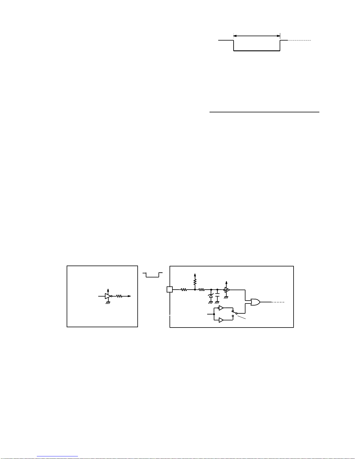
(Note) When the strobe signal is used in the continuous shutter mode to make ON/OFF control on a lighting source unit,
the following must be taken into consideration:
Wherever possible, use a strobe lighting unit or others that are equipped with a power source separated from that
of the camera (electrically isolated power source) and a trigger input terminal (photo coupler input, etc.). If a lighting
unit that shares a power source or a ground circuit with the camera is turned on or off by the strobe signal, the
image output from the camera mayhave noise due to the influence of the fluctuation of the power supply voltage or
change in the electric potential that occurs at the ON/OFF timing.
Even when the insulation aforementioned is applied, the electromagnetic induction may lead to the occurrence of
noise on the image signal if the electric current of the lighting unit to be control is large. In this case, a measure
must be introduced to reduce electromagnetic induction noise arising from the lighting unit.
(4-5) Test pattern display function
When connecting this camera to an image capture board for the first time,
the use of the test pattern display function of the equipment makes it
easier to confirm that the output timing of the camera and the details of the
signal connection conform to the specifications of the capture board.
When the test pattern function is set to be ON, the imaging device outputs
not pictures but the test pattern as shown on the right.
The pattern is output in 8 bit depth (R,G,B) and is displayed in order of
yellow(255,255,0),blue(102,255,255),green(0,102,0),black(0,0,0),white(255
,255,255),red(255,0,0),orange(255,102,0), purple(51,0,255).
< Switching procedure to output test pattern>
①
Turn a test pattern on by means of serial communication via Camera connector or Camera Link.
②
Confirm that the orange and green lamps of LED displayon the rear panel are blinking alternately.
③
Save settings by means of serial communication, if it is required to display a test pattern at next start-up.
(Note)The output level of the test pattern signal is not influenced by the setting value of Gain and Offset
The factory default setting is OFF. The setting can be changed to ON using serial communication command “H’27” with
the argument [H’01].
Shutter exposure time
Continuous lighting
STRB signal
Exposure
Exposure
Valid Useless lightingtime Valid Useless lightingtime
Strobe signal: Pin ** of
camera connector
+3.3V
100
6.8N
From internal circuit
74VHCT04A
(or equivalent)

N11A27;10/37
- 10 -
(4-6) Monitoring function for internal temperature of camera
This camera is equipped with an internal temperature sensor to monitor the temperature inside the camera housing. This
function makes it possible to use the camera in a safer way even in a harsh environment in terms of temperature, for
example use in the open air. With the use of serial communication commands, this function also works to control the
forced air-cooling fan of the camera and peripheral devices and others.
●How to monitor internal temperature of camera
The following two methods are available for monitoring the internal temperature of the camera:
●
Turn on the MENU display and confirm it by the OSD over the image. (Temperature to be displayed in Celsius)
●
Confirm it by temperature data to be returned in response to the serial communication command ”H’3C,H’3D”.
(Numerical conversion is required separately)
(Note) Carefully note that the temperature data obtained by this monitoring function is not for the ambient temperature but
the internal temperature of the camera.As a general rule, the internal temperature of the camera is higher than the
ambient temperature because of the heat generation associated with the consumed electric power inside the
camera. Even when the temperature monitored by this function exceeds the value of the “Operation ambient
temperature” shown in the specifications of the camera, no operational trouble will be caused as long as the
ambient temperature is lower than the value of the specifications, and sufficient countermeasures against
temperature are taken.
●Detection performance for temperature data
Temperature resolution : 0.5°
Update interval of data : 0.4 sec.
Temperature detection accuracy: ±2°C (-40°C to +85° C), +3 to -2°C (55°C to 125°C)
Effective data range : -55°C to 125°C (as long as the operation ambient temperature of the camera is
within the range defined by the specifications.)
●Temperature data by RS-232C communication
The temperature data to be returned in response to the “H’3C,H’3D” command of RS-232C is generated in the
following format:
[Data format]
The lower 10 bits out of the 16 bits of the returned data are valid.
XXXXXD9D8…D0 (invalid upper 6 bits/valid lower 10 bits as the data)
Db=B’D9D8…D0 in the binary system shows a signed integer value in two’s complement form.
However, the effective range of the temperature data is limited to the following due to the operational restriction of the
temperature sensor:
Effective range of temperature data: -110 (-55°C) to +250 (125°C)
(Note) The accuracy of the values of the temperature data is not guaranteed when the operation ambient temperature is
not within the range defined by the specifications.
[Conversion method from returned data to temperature in Celsius]
The temperature in Celsius is computed as Tc from the following formula where Dt is the signed integer number converted
from the above described 10 bit binary value of “Db=B’D9D8…D0”:
Internal temperature of camera: Tc=Dt × 0.5°C
(Example 1) Where Td, the returned value of the temperature data, is “H’0032” in the hexadecimal system, it is
expressed in the binary system as follows:
Td=H’0032=B’0000.0000.0011.0010
∴Db=B’00.0011.0010 =+50 (Only upper 10 digits of Td are valid.)
Then, Tc is calculated from the following formula: Tc=+50×0.5°C=+25°C

N11A27;11/37
- 11 -
(Example 2) Where Td, the returned value of the temperature data, is “H’03FA” in the hexadecimal system, it is
expressed in the binary system as follows:
Td=H’03F1=B’0000.0011.1111.1010
∴Db=B’11.1111.1010 (Only upper 10 digits of Td are valid.) →Dt=-6 (↓Refer to [Explanation])
Then, Tc is calculated from the following formula: Tc=Dt×0.5°C=-6×0.5°C=-3°C
[Explanation] Example of conversion algorithm from data in the complement number system to signed data
The following example shows how to convert 10 digit data in the complement number system into ordinary signed data:
(1)Whether the value is positive or negative is determined bychecking the uppermost bit (MSB) out of the 10 digit number.
When the MSB is 0, “+” is added, and when it is “1”, “-“ is added to the number (absolute value) to be obtained in
accordance with the below described (2).
(2) The absolute value is obtained from a binary number expressed in the remaining 9 digits including the lowermost bit
(LSB) as follows:
Simplyconvert into an integer number if the MSB is 0 (”+” sign) in accordance with (1).
Reverse each of all the 9 digits and add 1 to the result if the MSB is 1 (“-“ sign) in accordance with (1).
(3) The signed number is obtainedfrom (1) for the sign and (2) for the absolute value.
* In the case of the (Example 2) as above, its sign is “-“ because the MSB is 1 in accordance with (1). The absolute value
is “6” because of (invert(B'11111010)+ 1 = B'00000101 +1 = 5+1 =6) in accordance with (2). Therefore, this value (Dt) is
expressed as “-6” in the ordinary signed number system.
(4-7) Operation confirmation buzzer
The confirmation buzzer bleeps at the time of start-up after power is turned on and others.
The factory default setting is ON. This setting can be changed to cancel the buzzer.
[Procedure for switching buzzer between ON/OFF]
●The setting can be changed to ON using serial communication command “H’28” with the argument [H’01].

N11A27;12/37
- 12 -
Electronic shutter
operation mode
No shutter
operation
Electronic shutter
operation
Shutter
switch = 0
Shutter switch = 1 to 9
Asynchronou
s shutter
low speed
shutter
High speed
shutter
Preset
shutter
Pulse width
control
Continuous shutter
High speed
shutter
5. Various Settings
(5-1) Operation mode
●CCD output …Single out
(1 port output)
●Electronic shutter operation mode
Shutter mode …No shutter / continuous
/ asynchronous
Shutter speed category …High speed / low speed
/ pulse width control
(See the right schematic diagram)
●Scanning system …Normal scan
→Refer to the Section 6-3 for the specific setting
method.
(!) This camera does not support the asynchronous shutter mode
for the low speed shutter operation and the partial scan mode.
Table 5-1. Description of electronic shutter operation modes
Shutter mode
No shutter Electronic shutter is not used.
Exposure time of imaging device is equivalent to one frame time.
Exposure is continuously performed for each frame.
Continuous shutter Repeats exposure regardless of external trigger input (Vinit).
Repetition pitch is per frame.
Asynchronous shutter
Electronic shutter is released each time the external trigger is input (Vinit).
The permissible shortest repetition pitch is [exposure time + 1 frame time].
Type of
shutter speed
Normal shutter
(High speed shutter)
Shutter, the exposure time of which is less than one frame time, is used.
The shutter speed can be set as a preset shutter speed at 9 different levels both for the continuous
shutter/asynchronous shutter mode.
(!) As for the shutter speed of the conventional FC series cameras, 8 different levels for the
asynchronous shutter mode.
Low speed shutter The shutter, the exposure time of which is two frames or over, is used.
(Only for continuous shutter mode)
The shutter speed can be set as a preset shutter speed at 9 different levels.
(Note) This camera allows this setting only for the continuous shutter mode.
Pulse width control In case of the asynchronous shutter setting only, the shutter, shutter speed of which corresponds to the
pulse width (during Llevel) of the external trigger input (Vinit) , is released.
Shutter speed can be set as nH (n = 1 or larger integer number) in H (horizontal synchronous time) unit.
[Terminology] Preset shutter ·············This refers to the shutter speed setting other than those specified by the pulse
width control. More specifically, the shutter speed is preliminarily set by the
hypothetical shutter switch positions from “1” to “9” for the continuous shutter
operation or the asynchronous shutter operation. The shutter speed is defined in
the Table 6-1.
[Terminology] Pulse width control·······This is the way of setting or controlling the shutter speed by the width of the Vinit
signal that is externally input in the asynchronous shutter mode.
[Terminology] High speed shutter·······This means the shutter of which shutter speed is shorter than 1 frame time(=1
vertical synchronous time). The shutter speed is set as a preset fixed length of the
9 different levels that are determined by the position of the shutter switch
(continuous shutter and asynchronous shutter).
[Terminology] Low speed shutter ·······This means the shutter of which shutter speed is longer than 1 frame time. The
shutter speed is set as a preset fixed length of the 9 different levels that are
determined by the position of the shutter switch (continuous shutter).
(!) This camera does not support the functions of “low speed/asynchronous shutter” and “partial scan for the central area”.
Fig. 5-1 Electronic shutter operation modes

N11A27;13/37
- 13 -
・The operation modeofthecameracan be changedbychanging theargument data of theserialcommunicationcommand “H’21,H’22”.
Communication command H’21
LSB
MSB
Enabled STRB signal output
0 : OFF
1 : ON
H reset
0 : OFF
1 : ON
Selection of CC1 polarity
0 : Positive polarity
1 : Negative polarity
Not
used Not
used Not
used Not
used Not
used
Communication command H’22
LSB
MSB
Shutter operation
0 : No shutter
1 : High speed shutter
Asynchronous shutter
0 : OFF
1 : ON
Pulse width control/
Asynchronous shutter
0 : OFF
1 : ON
Not used
Long exposure
0 : OFF
1 : ON
Not
used Not
used Not
used
(5-2) Setting of shutter speed
The shutter speed is determined by assigning “0 - 9” to the shutter switch position or by specifying the shutter speed in H
(Horizontal scan time) unit.
As this camera is not equipped with the substantive shutter setting switch, the shutter speed is specified by means of serial
communication command via serial communication software. →Refer to section 6 for the details.
The shutter speed setting is mainly decided by setting position “0” to ”9” of (Hypothetical) shutter switch.
●Correspondence relation between Shutter speed and shutter switch setting
Table 5-2 Setting value of shutter speed
Shutter speed
Position of
shutter
switch
Highspeedshutter
(continuous/asynchronous) Lowspeed shutter
(continuous)
0 Noshutter(continuous) 1/20sec. (49.98 ms) (1920H=1V)
1 1/16000sec. (0.06 ms) (1H) 1/10.0 sec. (0.05sec) (2V)
2 1/7000 sec. (0.14ms) ( 3H) 1/6.7 sec. (0.15sec) (3V)
3 1/3800 sec. (0.26 ms) (6H) 1/5.0 sec. (0.20sec) (4V)
4 1/1800 sec. (0.54ms) (13H) 1/4.0 sec. (0.25sec) (5V)
5 1/750 sec. (1.34ms) (33H) 1/3.3 sec. (0.30sec) (6V)
6 1/370 sec. (2.70ms) (67H) 1/2.9 sec. (0.35sec) (7V)
7 1/185 sec. (5.41ms) (135H) 1/2.5 sec. (0.40sec) (8V)
8 1/89 sec. (11.28ms) (282H) 1/2.2 sec. (0.45sec) (9V)
9 1/44 sec. (22.53ms) (564H) 1/2.0sec. (0.50sec) (10V)
(Note) (H) and (V) in the table represent the horizontal time unit and the vertical time (frame time) unit respectively.
(Note) ”No shutter” in the table means the continuous shutter mode with exposure time = 1 frame time.
(Note) The value of the each shutter speed is the factory default value. The shutter speed of each position (excluding
shutter position = 0) is possible to change by the user with serial communication command.
(!)
“Shutter switch” means the hypothetical shutter switch set on the memory inside the camera via serial communication
command.

N11A27;14/37
- 14 -
Fig. 5-2 Conceptual diagram of gain and offset levels
(5-3) Level setting
The level setting is mostly divided into the
following two groups:
●Gain setting
This is to set the gain (amplification ratio)
of the preamplifier between the CCD
imaging device inside the camera to A/D
converter.
●Offset setting
This is to set the offset of the preamplifier
between the CCD imaging device inside
the camera toA/D converter.
→Refer to the next section (Section 6) for
the specific setting method.
(Note) As for the offset setting, it is recommended to use the factory default setting except for a special case.
(Note) Follow the procedure (gain setting →offset setting) if fine tuning of the offset value is required.
(5-4) MGC gain setting value (Manual gain control)
●Variable gain amplifier and integrated gain
The image signal output from CCD is amplified inside the camera
through the following fixed gain amplifier and then through the
variable gain amplifier before being input into theA/D converter.
The left block chart shows this flow.
(Note) The gain value (dB) describedhere is the one based on the CCD output (0 dB) as the baseline.
The equipment is controlled by giving 0 to 255 as the MGC setting value.
The correlation between this setting value and the MGC gain (Preamplifier
gain) is shown in the right graph.
(Note)When the CCD element receives excessive light with a low
gain value of the amplifier, the signals of the nonlinear section of the
CCD element and the preamplifier are output at the high brightness
area due to the restriction of the dynamic range of the CCD light
receiving element.
In this state, unnatural image (Note below) may appear in the
neighborhood of the saturating signal area of the image due to the
characteristic of the nonlinear section.
This phenomenon, which is associated with the saturation characteristic
of the CCD element, is not a failure arising from the camera.
→To eliminate this phenomenon, reduce the amount of light by stopping
down the lens and newly set a higher gain value. Then, the output signal
from the CCD element at the saturating area will be appropriately saturated
into a white level for the output.
(Note)The above described unnatural image represents the following states:
●Black and white look inverted at the saturating area.
●The outline of the saturating area is blurred.
●The saturating area slightly shifts upward or downward.
●The brightness value of the saturating area does not reach 1023. (when in 10 bit output)
Ti me
T ime
Ti me
1 0 2 3
0
0
1 0 2 3
0
In cr ea se in O FF SET
In cr eas e in GA IN
I mag e si gna l
1 0 2 3
(B efo re s et tin g ad ju stm en t )
Si gn al le ve l
S ig nal l ev elSi gn al l eve l
CCD
P r eam pl ifi er
A/D
GAIN
V a ri a bl e g ai n a mp l if ier
5.1dB
~
32. 6dB
I nteg rat ed g ai n
MGC setting
Fi xed g a in a m pl ifi er
1dB(Fixed) 6.1 dB
~
33.6dB
42
36
30
24
18
12
6
0 64 128 192 (255)
MGC GAINCODE
MGC GAIN (dB )

N11A27;15/37
- 15 -
(5-5) Data save and data read setting
This camera incorporate nonvolatile memories and various operation mode settings and level settings can be
stored on them. And the data set at each address is overwritten with the contents of nonvolatile memories at the
time of power-on.
Execute the following commands to save data.
Enter an argument [H’01] to communication command ”H’DC”(Enabled communication for EEPROM)
Enter an argument [H’01] to communication command ”H’DA”(Save data set by each command)
(!) This camera does not have the “Program page setting” function.
Execute the following commands to read out saved data.
Enter an argument [H’01] to communication command ”H’DC”(Enabled communication for EEPROM)
Enter an argument [H’01] to communication command ”H’DB”(Read data saved by each command)

N11A27;16/37
- 16 -
6. How to Change Setting
(6-1) How to set hypothetical shutter switch
The shutter speed is determined mainly by the setting positions of the hypothetical shutter switch from “0” to “9”.
It can be set bychanging the argument data of the communication command “H’32”.
Table 6-1 Setting value of shutter speed
Shutter speed
Position of
shutter switch
Argument
data
Highspeedshutter
(continuous/asynchronous) Lowspeed shutter
(continuous)
0 H’00 Noshutter(continuous) 1/20sec. (49.98 ms) (1920H=1V)
1 H’01 1/16000sec. (0.06 ms) (1H) 1/10.0 sec. (0.05sec) (2V)
2 H’02 1/7000 sec. (0.14ms) ( 3H) 1/6.7 sec. (0.15sec) (3V)
3 H’03
1/3800 sec. (0.26 ms) (6H) 1/5.0 sec. (0.20sec) (4V)
4 H’04
1/1800 sec. (0.54ms) (13H) 1/4.0 sec. (0.25sec) (5V)
5 H’05
1/750 sec. (1.34ms) (33H) 1/3.3 sec. (0.30sec) (6V)
6 H’06
1/370 sec. (2.70ms) (67H) 1/2.9 sec. (0.35sec) (7V)
7 H’07
1/185 sec. (5.41ms) (135H) 1/2.5 sec. (0.40sec) (8V)
8 H’08
1/89 sec. (11.28ms) (282H) 1/2.2 sec. (0.45sec) (9V)
9 H’09
1/44 sec. (22.53ms) (564H) 1/2.0sec. (0.50sec) (10V)
(Note) (H) and (V) in the table represent the horizontal time unit and the vertical time (frame time) unit respectively.
(Note) ”No shutter” in the table means the continuous shutter mode with exposure time = 1 frame time.
(Note) The value of each shutterspeed is the factory default value.
(6-2) How to set manual shutter exposure time
The shutter exposure time(16 bit wide) can be changed in H unit.
The upper data can be changed using the communication command “H’30”.
The lower data can be changed using the communication command”H’31”.
Example of the 2H exposure time.
Enter the argument [H’00] to communication command ”H’30”
Enter the argument [H’02] to communication command ”H’31”
(6-3) How to set operation mode
Table 6-2 [OSD menu1] setting
(Note)The scanning mode is always fixed to “All pixels ”scan mode with this camera.
※
1 There are two ways to change the “shutterspeed”: hypotheticalshutter switch setting and manual shutterspeedsetting.
※
2 The continuous shutter / the asynchronous shutter can be switched by changing the operation mode of the camera.
Communication
command Set contents Argument data
Default Setting range
H’20 Menu display (MENU) H’00
H
’
00:Nondisplay
H’01:Menu 1
H’02:Menu 2
H’03:Menu 3
H
’
04:Menu 4
H’34 MGC setting (GAIN) H’00 H’00 to H’FF
H’33 Digital offset (OFFSET)
H’
**
H’00 to H’FF
※
1 Shutter exposure time (S,TIME) H’01FF Refer to ch.5
H’22
※
2
Continuous/asynchronous shutter (S.FORM)
H’01 Refer to ch.5
- All pixels/partial scan (SCAN) All pixels Fixed to “All pixels”
H’29 Monitor ON/OFF (MONITOR) H’01 H’00: OFF
H’01: ON

N11A27;17/37
- 17 -
●Menu display
It can switch the menu displayed by OSDfunction. Refer to section 6-6 for more information about the displayed menu.
The OSD menu can be switched by entering the argument [H’00
~
H’04] to the communication command “H’20”.
●MGC setting (Manual gain control)
The gain of the camera is controlled by giving “0 to 255” to the Variable gain amplifier as the MGC setting value.
MGC amplifies the image signal output from CCD through the Variable gain amplifier on the subsequent stage.
The gain value can be set byentering the argument [H’00
~
H’FF] to the communication command “H’34”.
●Digital offset
It can set the offset value of the preamplifier in between CCD imaging device andA/D converter.
The offset value can be set by entering the argument [H’00
~
H’FF] to the communication command “H’33”.
●Shutter exposure time
The shutter exposure time can be set in H unit.
“6-1 Hypothetical shutter switch”
It can be set by changing the argument data of communication command “H’32”.
“6-2 Manual shutter exposure time”
It can be set by changing the argument data of communication command “H’30,H’31”.
●Continuous /asynchronous shutter
” Continuous shutter /Asynchronous shutter” can be switched by changing the operation mode of the camera.
Communication command H’21
LSB
MSB
Enabled STRB signal output
0 : OFF
1 : ON
H reset
0 : OFF
1 : ON
Selection of CC1 polarity
0 : Positive polarity
1 : Negative polarity
Not
used
Not
used
Not
used
Not
used Not
used
Communication command H’22
LSB
MSB
Shutter operation
0 : No shutter
1 : High speed shutter
Asynchronous shutter
0 : OFF
1 : ON
Pulse width control/
Asynchronous shutter
0 : OFF
1 : ON
Not
used Long exposure
0 : OFF
1 : ON
Not
used Not
used Not
used
Example: In case of “Enabled strobe signal, H reset ON, CC1 positive polarity andAsynchronous shutter”,
Enter the argument [H’03] to the communication command H’21.
Enter the argument [H’02] to the communication command H’22.
●Monitor ON/OFF
The ON/OFF status of the digital signal output from the HDMI connector can be controlled.
It is recommended to turn the monitor output OFF for power saving when using only the Camera Link output or when not
using the monitor output for a long time.
Table 6-3 [OSD menu 2] setting
Communication
command Set contents Argument data
Default Setting range
H’37 RED digital gain (R-GAIN) H’40 H’00 to H’FF
H’35 GREEN digital gain (G-GAIN) H’40 H’00 to H’FF
H’38 BLUE digital gain (B-GAIN) H’40 H’00 to H’FF
H’39 Digital gain ON/OFF (D-GAIN) H’00 H’00: OFF
H’01: ON

N11A27;18/37
- 18 -
●RED digital gain
It can change the RED digital gain when outputting Camera Link signal and RGB 8bit signal for the monitor.
Variable range is approximately 0.01 to 4-fold when assuming 0x40 as reference 1-fold in a fixed-point system.
Also, the sampling value (the average value of 15 points when
Gain is invalid) of each RGB output is displayed on OSD.
Example: When it is needed to multiply the RED digital gain by 1.25,
Enter the argument [H’50] to the communication command H’37.
●GREEN digital gain
It can change the GREEN digital gain when outputting Camera Link signal and RGB 8bit signal for the monitor.
Variable range is the same as that of RED digital gain.
●BLUE digital gain
It can change the BLUE digital gain when outputting Camera Link signal and RGB 8bit signal for the monitor.
Variable range is the same as that of RED digital gain.
●ON/OFF of the digital gain
It can confirm the status of digital gain of each RGB color. When this command is set to ON, any one of RED digital gain,
GREEN digital gain and BLUE digital gain is in valid status. If it needs to set the Digital gain to invalid status, change the
digital gain value of each color to H’40 or turn the one push white balance OFF.
Table 6-4 [OSD menu 3] setting
※
2 “H reset” is switched by changing the operation mode of the camera.
(Note) Vsub voltage is appropriately adjusted before shipment, and therefore the setting value should not be changed
without a special reason. If the value is changed by mistake, it can be reset to the factory default by executing
“(6-5) Read out of factory default”.
[Explanation] Vsub voltage
Vsub voltage is the bias voltage (substrate voltage) that serves to control the blooming effect (resulting in blur or running
image at a saturating area) that arises from excessive light getting into CCD.
If a high Vsub voltage is set, the blooming effect can be reduced, although an excessively high voltage leads to a narrower
operation range of CCD because it is associated with a decrease in the saturating voltage of the CCD output.
It is appropriately set before shipment because the optimum Vsub voltage varies by CCD.
Communication
command Set contents Argument data
Default Setting range
- Serial communication baud rate (BAUDP) 9600 bps Fixed value
H’27 Test pattern (PATTERN)
H’00 H’00 : OFF
H’01 : ON
H’26 Camera link output bit (BIT) H’00 H’00 to H’03
H’21
※
2 H reset (H-RESET) H’02 See Operation mode
setting
H’3A Vsub voltage (VSUB) H’
✳✳
H’00 to H’FF
H’21
※
2 Continuous shutter strobe signal (STRB-C) H’02 See Operation mode
setting
H’21
※
2 Vinit2 polarity (Vinit2) H’02 See Operation mode
setting
H’28 Operation confirmation buzzer (BZ) H’01 H’00 : OFF
H’01 : ON
M E N U 2
M E N U : O N
R - G AI N : H ' 6 A (H ' 6 3 )
G - G AI N : H ' 4 0 (H ' 5 2 )
B - G AI N : H ' 5 0 (H ' 4 1 )
D - G AI N : O N
M S = - S S = 7
F S 2 3 0 0 D V [ V . . ]
Output when Gain
is invalid
Gain set va lue

N11A27;19/37
- 19 -
●Serial communication baud rate
The serial communication baud rate of this camera is fixed to 9600 bps.
●Test pattern
It outputs the color bar signal from the camera as the Camera link output and monitor output.
Refer to the section (4-5) “Test pattern display function” for more details.
●Camera link output bit
The Camera link output format can be switched between Bayer 8bit, Bayer 10bit, Bayer 12bit, and RGB 8bit.
It can be changed by entering an argument to the communication command “H’26” as follows.
H’00 : Bayer 10bit
H’01 : Bayer 8bit
H’02 : Bayer 12bit
H’03 : RGB 8bit
(Note)The monitor output bit cannot be changed.
●H reset
“H reset” is switched by changing the operation mode of the camera. Refer to (5-1) “Operation mode”.The concrete
example is described in
paragraph “●Continuous /asynchronous shutter” of
Table 6-2 [OSD menu1] setting.
●Vsub voltage
Vsub voltage is appropriately adjusted before shipment, and therefore the setting value shouldnot be changed without a
special reason. If the value is changed by mistake, it can be reset to the factory default by executing “(6-5) Read out of
factory default”.
●Continuous shutter strobe signal
“
Continuous shutter strobe signal
” is switched by changing the operation mode of the camera. Refer to (5-1)
“Operation mode”. Aconcrete example is described in paragraph “●Continuous /asynchronous shutter” of Table 6-2
[OSD menu1] setting.
●Vinit2 polarity (CC1)
“Vinit2 polarity” is switched by changing the operation mode of the camera. Refer to (5-1) “Operation mode”.Aconcrete
example is described in
paragraph “●Continuous /asynchronous shutter” of
Table 6-2 [OSD menu1] setting.
●Operation confirmation buzzer
The confirmation buzzer bleeps when the power is turned on or at the end of serial communication.
The Operation confirmation buzzer can be set to OFF byentering the argument [H’00] to the communication command
“H’28”.

N11A27;20/37
- 20 -
Table 6-5 [OSD menu 4] setting
●Selection of Operating cursor
It can select the cursor to be changed and to display the settings. It can be changed by entering the argument [H’01 to
H’04] to the communication command “H’45” as follows.
H’01 : to display the data of cursor1 (White)
H’02 : to display the data of cursor2(Blue)
H’03 : to display the data of cursor3 (Green)
H’04 : to display the data of cursor4 (Red)
●Horizontal data Start / Width
It can set the horizontal start position and the horizontal width of each cursor in pixels. It can be changed by entering an
argument to the communication command H’A0 to H’BF. Refer to the command list on chapter 7.
(Note)The sum of the coordinate data of the horizontal start position and the horizontal width should not exceed the
setting range of “H’0018 ~ H’064C”.
Setting of horizontal start position
Incase of cross-shapedcursor,
the widthis not changed even if it wereset.
Display area of the monitor
Setting of horizontal width
●Vertical data Start / Width
It can set the vertical start position and the vertical width of each cursor in pixels. It can be changed by entering an
argument to the communication command H’A0 to H’BF. Refer to the command list on chapter 7.
(Note)The sum of the coordinate data of the vertical start position and the vertical width should not exceed the
setting range of “H’0007 ~ H’04C4”.
Display area of the monitor
Setti ng of Verti cal
start position
Incase of cross-shapedcursor,
the widthis notchanged evenif it were set.
Setti ng of verti cal wi dt h
Communication
command Set contents Argument data
Default Setting range
H’45 Operating cursor (CURSOR) H’01 H’01 to H’04
H’
✳✳
Horizontal data Start / Width (X_DATA SX/W)
- H’0018 to H’064C
H’
✳✳
Vertical data Start / Width (Y_DATA SY/W) - H’0007 to H’04C4
H’40 Cursor 1 Set (White) (CURSOR 1) H’00 H’01 to H’03
H’41 Cursor 2 Set (Blue) (CURSOR 2)
H’00 H’01 to H’03
H’42 Cursor 3 Set (Green) (CURSOR 3)
H’00 H’01 to H’03
H’43 Cursor 4 Set (Red) (CURSOR 4)
H’00 H’01 to H’03
Table of contents
Other Takenaka System Security Camera manuals