12 13
7. ORDER OF OPERATION
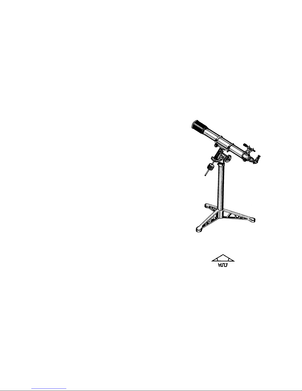
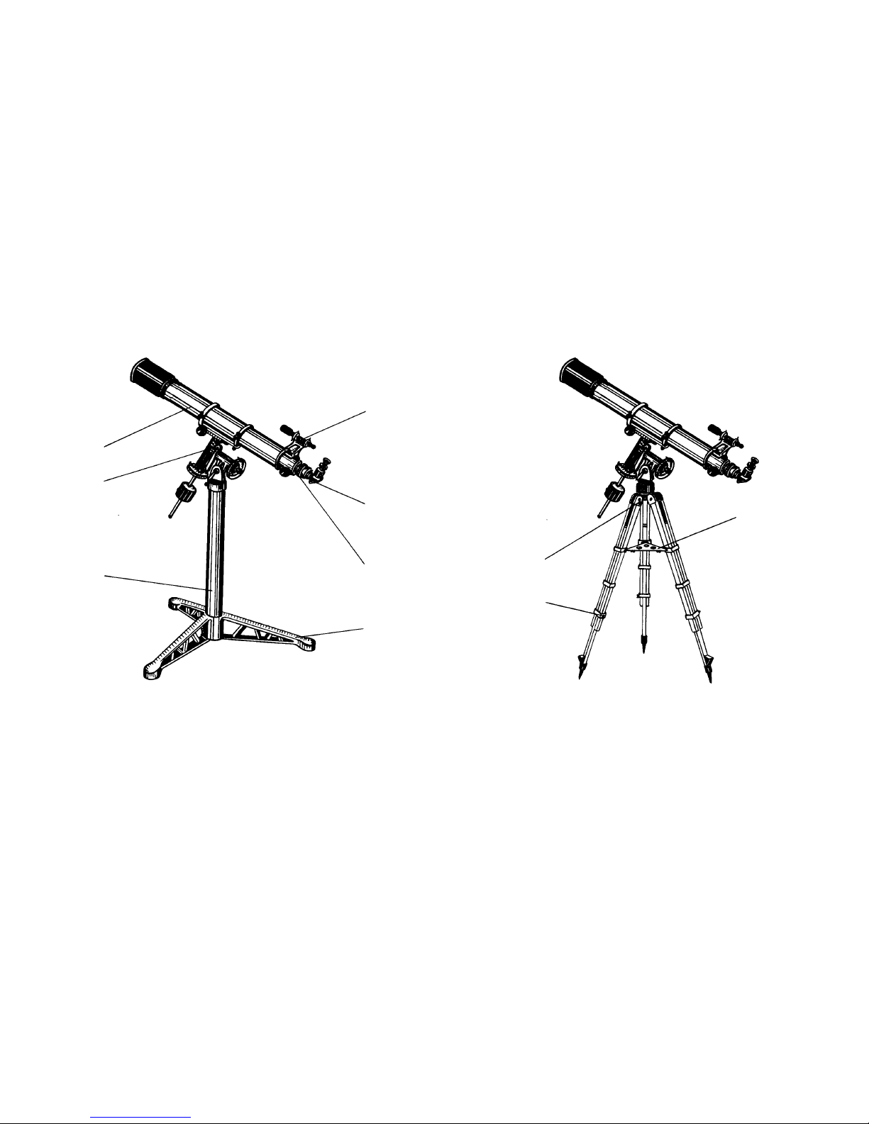
7.1. Operation with telescope
Before mounting the telescope it is required to choose the place and prepare
the site. It must be even and solid. Mount the telescope on the site and check it
for tenable stability.
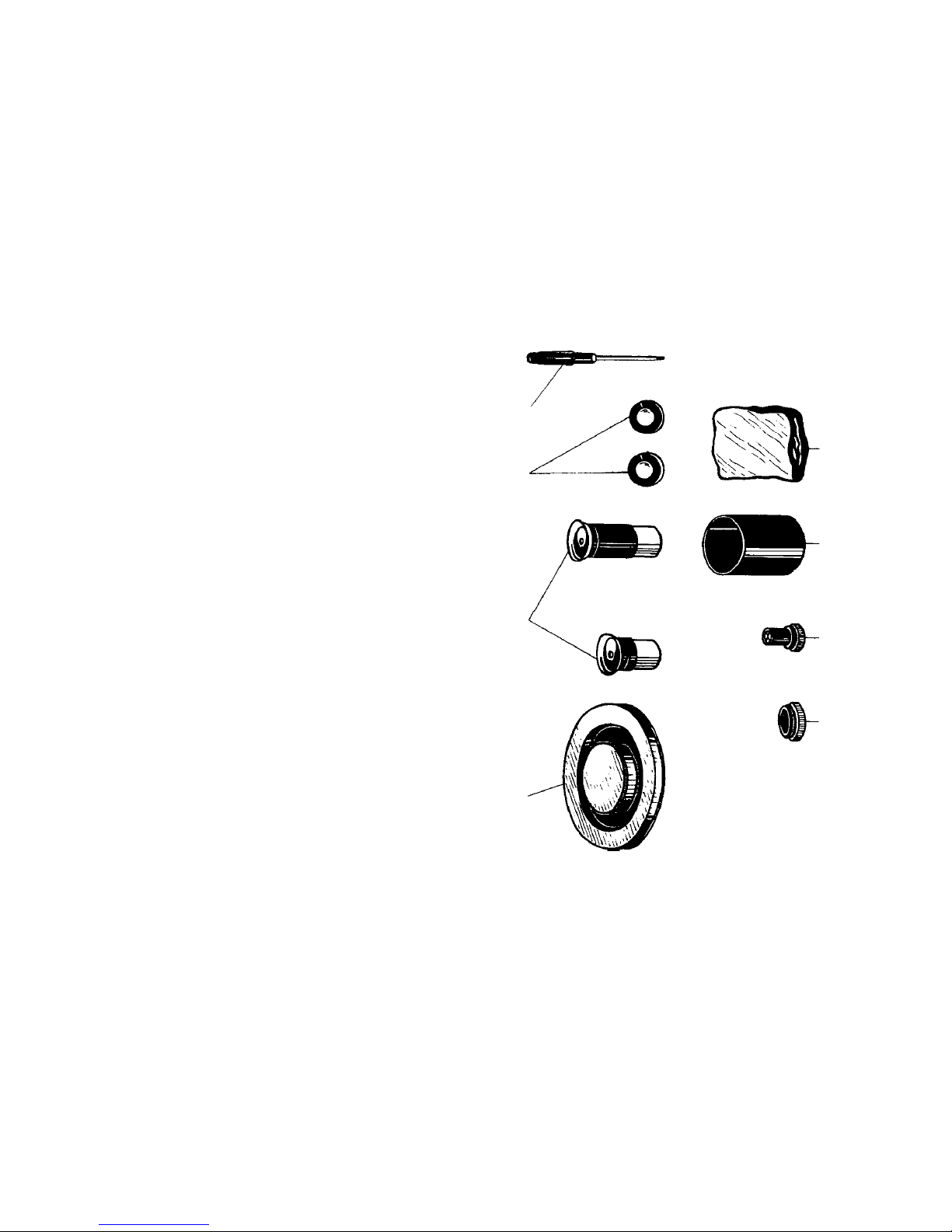
After mounting the telescope it is required to set parallelism of the optical
axes of the telescope tube and finderscope. For this purpose one should insert
a reticle 7 (fig. 5) into eyepiece f'=25mm and to insert the eyepiece together
reticle into eyepiece set. Then the telescope is pointed to the remote object.
The position of the telescope is fixed by means of the screws of the brakes of
the axes.
Then, by operating with the setting screws of the rings of fiderscope, one
brings the chosen remote object to the centre of the findelscope view field.
This operation is performed only once. In the future before observation only
the parallelism of the optical axes of the telescope and finderscope is checked.
The celestial sphere together with astronomical objects performs the visible
motion about the celestial axis. Therefor the telescope is provided with equatorial
mounting. Being set correctly, this mounting makes it possible to perform to
the celestial object tracking. After pointing the telescope to the object the
observer can keep the object in the view field center for a half a haul by rotating
slowly the micrometer screw of the polar axis.
In order to avoid guiding collection in declination, the polar axis of the
telescope should be set parallel to celestial axis. In this case the north (upper)
end of the polar axis faces the celestial pole positioned near Polaris (a Ursae
Minoris). For visual observations it is enough to incline the polar axis at an
angle equal to the latitude of the observing site and direct it approximately
along the line the South - North. With such setting of the telescope the object
will deviate step by step in declination (it is lifted or lowered in the view
field). This error is corrected occasionally by means of the micrometer screw of
the declination axis.
For photographic operations and in the cases when the telescope can be set
stationary, the polar axis of the telescope should be set precisely. For this purpose
one observers any blight star in the East, then in the South and makes notice of
the direction of the star displacement.
If in the observation of the star in the East it is disposed in the telescope view
field so that in its tracking the upper end of the telescope tube sinks slowly, the
north end of the three polar axis should be somewhat lifted.
If the upper end of the tube Is lifted step by step, the north (upper end of the
polar axis should be lowered.
For precise setting of the axis by azimuth one observes the star near the
meridian circle (above the South point) in the same way. If in the star tracking
one has to lower slowly the upper end of the telescope tube, the north end of
the polar axis should be displace to the West.
If in the process of the star tracking the upper end of the telescope tube I
lifted, the north end of the polar axis should be displaced to the East.
In 20-30 minutes of such observations one can set the polar axis so that the
star will remain on the cross-hairs for 10-15 minutes without correction in
declination.
After precise setting of the polar axis one can set the declination and haul
elides which must help to search the objects invisible with a naked eye or even
through the findelscope.
First of all one should set the hour elide which is fixed on the polar axis.
After fine setting of the polar axis set the declination axis horizontally. The
horizontal setting should be checked with the aid of a level. After setting the
axis one sets the haul elide so that «0» is found against the index. Fix the circle
by means of brake.
For setting the declination circle fixed on the declination axis one should
find the declination of two-three bright stars in the star catalogue or make use
of the declinations of the planets. With the help of the findelscope one brings
the star or the planet to the center of the field of view of the telescope at maximum
magnification. After that one sets the declination of the required star against
the index. The circle is to be fastened with a screw. Then one makes attempt to
find the second star by its declination. For this purpose one slackens the screws
of the axis brake and adjusts the telescope so that the declination of the star to
be sought is set on the declination circle. Fix the declination axis by rotating
the telescope tube slowly clockwise hound the polar; bring the star to the center
of the telescope field of view. After checking of the circle setting one tightens it
with a nut.
In order to avoid resetting of the polar axis and elides one should choose a
solid horizontal site. Best of all it is made of some concrete of 1.5x1.5 m size.
The position of three supports of the telescope pier should be marked on the
site. The telescope is mounted according to the marks on the concrete site.
7.2. Photographic observations
Photographing star fields is carried out with the use of the telescope in the
main focus. To make it one should use a small size 35 mm camera or other
devices having fitting thread of 42x1.0mm or 42x0.75mm. To mount a camera
it is necessary to remove an eyepiece set 3 (fig. 1) from tube and to mount a
camera with 42 x 1.0 mm thread. If it is necessary, one should use an adapter
8 (fig. 5) to mount a camera with 42 x 0.75mm thread. Mounted a camera one
should make a focus it and to balance the telescope.