TASKalfa 3500i User manual

2012.3. 8 Revised
3.16Revised
3.19Revised
3.21Revised
4. 6 Revised
8.30 Revised
2013.11.18 3rd Edition
3500i/4500i/5500i/6500i/8000i
Troubleshooting Guide
1

Content
2
Item Phenomeno
3500i/4500i/5500i 6500i/8000i Pages
Image Toner Color Dot / Color Mark ○ ○ 4-5
Void Line / White Band ○ ○ 6-9
Void Line / Black Band(Vertical Black Stripes)○ ○ 10
Image Smudges ○ ○ 11-23
Light Image ○ ○ 24
Edge Part Background ○ ○ 25
Measure for Condensation ○ ○ 26
DP-770 Tip50mm・End37mm Character Blurring ○27-28
Conveying
J0501~7 / J0523~7○ ○ 29-30
J051X ○ ○ 31
J05X8/J44XX ○ ○ 32
J0545 (PF-770) ○ ○ 33
PF-770 Repair for the procedures slope confirmation of TRAY PAPER ○ ○ 34
J1313 / J1314 ○ ○ 35
J150X/J1904 ○ ○ 36
J1512 ○ ○ 37
J341X(PF) ○ ○ 38
J4103/ J4104 ○ ○ 39
Abnormal Sound/J42XX/J40XX(Add Intermediate Motor Cover)○40
J42XX/Fixing Separation Claw Tip Missing or Damaged ○41
J421X/ J460X/ J470X ○○(J460Xのみ) 42-43
Torn Paper、J430X/431X/440X/471X, 60mm from bottom edge ○44
○ ○ 45
J49XX/ J50XX/ J51XX/ J600X ○ ○ 46-54
J610X/ J611X(DF) ○ ○ 55-60
J631X/ J641X/ J650X(DF) ○ ○ 61-63
J6510 (DF-790 Caution of Manual Staple) ○ ○ 64
J6600 (DF) ○ ○ 65
J6710 / J7710 (BF) ○ ○ 66
J9020/J9030 ○ ○ 67
J9010 / J9011 / J9110 / J9300 / J9310 / J9400 / /J9600 / J961 ○ ○ 68
Dog Ears ○ ○ 69-74
Paper Wrinkles ○ ○ 75-76
BF-730/720/710 Paper Wrinkle Correspondence of 1 Sheetsof Paper
When Folded in the Middle
○ ○ 77

Content
3
Item Phenomeno
3500i/4500i/5500i 6500i/8000i Pages
C-CALL C0640
○ ○
78
C2101
○ ○
79
C2201
○ ○
80
C510X
○ ○
81
C6000/C6030/C6050/C6200/C6230/C6250
○
82
C6020/C6220
○
83
C6020/C6030/Fixing Roller Fusing, Poor Fixing
○
84
C6030/C6050
○
85
C6600/C6720/Fixing Belt Damage
○
86-90
C6620
○
91
C6730
○ ○
92
C6770
○
93
C6910
○ ○
94
C7101
○ ○
95
C9500/C9510/C9520/C0630/C0640/CF245 SATA Cable Failture
○ ○
96
CF000/“Welcome” Screen Lock
○ ○
97
CF040
○ ○
98
CF182/186
○ ○
99
Abnormal Sound From Developing Unit
○ ○
100
Abnormal Sound From Fixing Drive Unit
○
101-105
DP Motor Driven Sound
○ ○
106
Others DP Size Detection Error
○ ○
107
Disporsal Toner Bottle
○
108
Time for maintenance.(T)
○ ○
109
Damage of Cassette Rail
○ ○
110-111
Abnormal
Sound

4
Black Dot / Black Marks
Image sample 1
1.126mm interval Black Dots (drum)
If one of several 126mm interval black dots appears randomly at sub scanning
direction, take the following measure.
(Image sample 1)
(*there is the case that the black dots appearance becomes vertical line.)
a.Replace the DRUM ASSY (DK-6305/6705).
126mm

Black Dot / Black Mark
2. 45mm interval Black dots
If 45mm interval paper appears at image in the sub
scanning direction, take the following measure.
a. Check whether the foreign substance are attached
on the developing roller surface.
b. If the foreign substance attached, wipe off by the
clean cloth.
c. If no foreign substance attached or it will not be
disappeared after wiping off, replace the developing
unit.
Image φ0.1~0.3mm
45mm
Above is to check the
black dots on the paper
by the Magnifying glass.
1. 38mm interval black dots, black marks (Charger roller)
Take the following measure if the 38mm interval black dots or marks appear
at the image In the sub scanning direction.
a. Check the 38mm interval to print out the test sample by U089 Mono4.
b. Replace the MC-6705 after confirming the dots appears 38mm interval.
c. Execute U930 charger roller counter reset after replacing MC-6705.
38mm
5

a. If the void image appear at solid part of prints out on U089 Color
Belt, refer to below “b” * If the vertical streak image appears at the
halftone, replace the developing unit.
b. Execute U140 AC CalibHigh Altitude
c. Select “Altitude” and find the setting which the leak image does not
appear. * Avoid the setting far from the actual altitude.
d. If the image will not be recovered, replace the developing unit.
Image sample 1
◇Leak at the solid part
Void image appear at the solid part.
U89 Sample set
Void image at
Solid part
Image sample 2
◇Leak at the halftone part
Horizontal streaks appear at Halftone image.
U89 Sample set
Horizontal streaks
at halftone image
Void Line / White Band (Horizontal White Streaks)
1. Leak Image 1 (3500i、4500i)
Execute AC Calib Operation Automatically Select AC Calib High Altitude Setting
7550ci/6550ci O
5550ci/4550ci O
3550ci/3050ci O
8000i/6500i O
5500i O
4500i/3500i O
6

a. If the void image appear at solid part of prints out on U089 Color
Belt, refer to below “b” * If the vertical streak image appears at the
halftone, replace the developing unit.
b. Check the value of U140 Sleeve AC (1)
c. U140 Execute AC Calib(2)Set “K” Off to
On(3)Execute(4)Start
d. Check whether the value of U140 SleeveAC (3) becomes lower
and the image is recovered.
e. If the image will not be recovered, replace the developing unit.
(3)
(4)
(1)
(2)
Image sample 1
◇Leak at the solid part
Void image appear at the solid part.
U89 Sample set
Void image at
Solid part
Image sample 2
◇Leak at the halftone part
Horizontal streaks appear at Halftone image.
U89 Sample set
Horizontal streaks
at halftone image
Void Line / White Band (Horizontal White Streaks)
1. Leak Image 2 (5500i、6500i、8000i)
Execute AC Calib Operation Automatically Select AC Calib High Altitude Setting
7550ci/6550ci O
5550ci/4550ci O
3550ci/3050ci O
8000i/6500i O
5500i O
4500i/3500i O
7

Void Line / White Band
2. Horizontal white streaks (Image sample 1)
If 1.2mm interval horizontal streaks occur at
the gray image in the main scanning
direction, take the following measure. *In
case of this appearance at the machine’s
rear side is more noticeable than at front.
a. Replace the LSU.
Image sample 1
About
1.2mm
Machine
Front
Machine
Rear
8

Void Line / White Band
3.Vertical White streaks (Image sample 1)
If vertical white streaks appears continuously and
linearly in the sub scanning direction, take the
following measure.
a. Clean the cover glass on the LSU.
Image sample 1
Vertical white streaks
Image sample 2
4. Vertical White lines (void image) (Image sample 2)
If the void image appears by wide width in the sub scanning direction, take
the following measure.
a. Replace the LSU. (In case of the machine is produced before 2011 Oct.)
9

1. Vertical Black streaks (Image sample 1)
It occurs continuously and linearly toward the paper feeding direction.
Please remove the transfer belt unit and check whether the transfer belt is cracked.
1. When the transfer belt is torn or cracked, please replace the drum unit and the transfer belt unit.
2.Check the firmware version (U019) and upgrade it higher than Upgrade Pack Ver. V4.00
Image sample 1
Void Line / Black Band
Vertical Black Streak
Condition of tear or crack on the transfer belt
10

Image Smudges (1/13)
Image sample 2
View from
bottom part of
ejected paper
2.Image Smudges (Image sample 2)
The smudges appears at the leading edge of ejected
paper.
Clean the duct at inside if machine and the
developing unit.
Refer to “3.Cleaning Procedure” for cleaning.
1.Image Smudges (Image sample 1)
There is no periodicity and it occurs intermittently
in the paper conveyance direction.
a. Clean the conveying guide.
b. Clean the paper dust cleaner at the regist roller
section.
(-->)
Image sample 1
Cleaner
11

(Stains on the conveying guide)
The stains occur at the outside of paper path.
3. Cleaning Procedure Image Smudges (2/13)
a. Preparation before cleaning
Remove the lower rear cover and toner box
(Fig.1)
Remove the developing unit and drum unit
after detaching the inner unit .
Remove the toner box.
2 screws
Fig.1
b. Clean the conveying guide .
Clean the paper feeding side of the
conveying guide (Fig.2)
At the next, remove the conveying guide
(one each at front and rear), clean the back
side of conveying guide (Fig.3)
* For cleaning, use the dry and soft cloth. (It
locates at the size indication plate slot on
1st cassette.) Clean the conveying guide
Screw
Fig.2
Fig.3
12

Image Smudges (3/13)
c. Clean the toner exhaust duct at inside of
machine
While the developing unit is taken out and the
conveying guide is removed, suction the toner
exhaust part at inside the machine where the
toner exhaust duct of the developing unit
connected with a cleaner. (Fig.4)
Note) Clean while paying attention not to scratch the gear and registration roller.
(Before
cleaning)
Tone is
accumulating.
(-->) Toner ExhaustAperture
Fig.4
d. Check the machine’s production month
Check the production month from the
machine’s serial number on the rating label and
clean it according to the production month.
・Before 2012/Feb. production machine.
Refer to the cleaning procedure “e”
”g”
・After 2012 / Mar. production model.
Refer to the cleaning procedure “f”
“g”
MACHINE No. N4P22*****
16 : 2011/6
17 : 2011/7
18 : 2011/8
19 : 2011/9
1X : 2011/10
1Y : 2011/11
1Z : 2011/12
21 : 2012/1
22 : 2012/2
23 : 2012/3
24 : 2012/4
25 : 2012/5
(Rating label) (Way of refer to the
production month)
N4P:Model
Number
It differs
according to
the model
22:Indicate
2012 Feb.
production
13
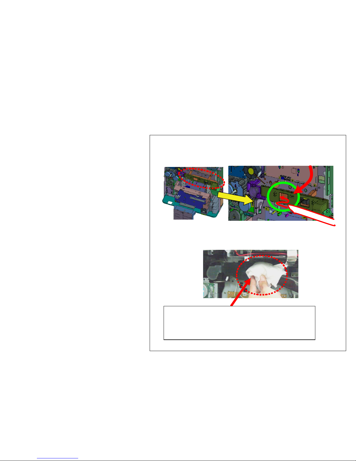
Image Smudges (4/13)
e. Clean the DUCT TONER UNIT
( In case of 2012 Feb. production machine)
Clean the DUCT TONER UNIT with the vacuum
cleaner.
Procedure 1) Clean and suction the outlet of duct with
cleaner for 1 min.
Acleaner tip is put in and attracted from this direction.
(If a opening is covered with a rag etc. so that the open
air may not be attracted from a cleaner tip, toner can
be attracted effectively.)
14

Image Smudges (5/13)
Procedure 2)
Remove the 302LF33012/DUCT FAN TONER
from the machine and clean, suction it with the
vacuum cleaner.
Reattaching the seal after cleaning and cut the
part of duct.
302LF33012/DUCT FAN TONER
Remove the duct
with 2 screws
Lift up this
part if it is
detached.
Clean the removed duct
Clean after removing the duct too.
(Before cleaning )
Toner is accumulating.
15

Re-attach with 302LF33201/SEALTONER
DUCTA (Change with 5mm thick sponge)
Cut the rib (claw) of the duct.
Procedure 3)
Peel off the FILM of 302LF33012/DUCT FAN
TONER and replace with 302LF94410/PARTS LID
TONER FAN ASSY(ZG) SP
302LF94410/PARTS LID TONER FAN ASSY(ZG) SP
FILM
302LF94410 is re-usable.
After this replacement, the level of unit is same
as 2012 Mar. and after production model.
Please replace with the parts as shown in fig when
302LF94410/PARTS LID TONER FAN ASSY(ZG)
SP.is available.
Image Smudges (6/13)
16

f. Clean the DUCT TONER UNIT
(In case of 2012 Mar and after production
machine)
Clean suction the DUCT TONER UNIT with
the vacuum cleaner.
Procedure 1) Clean suction the duct outlet for 1 min with
the vacuum cleaner.
Acleaner tip is put in and attracted from this direction.
(If a opening is covered with a rag etc. so that the open
air may not be attracted from a cleaner tip, toner can be
attracted effectively.)
Image Smudges (7/13)
17

Procedure 2)
Remove the 302LF33830/LID TONER FAN from
the machine and clean suction it with the vacuum
cleaner.
(Before cleaning )
Toner is accumulating.
LID TONER FAN
Remove it after releasing 3
pcs of snap-fit
Return the LID TONER FAN at original position after cleaning
Image Smudges (8/13)
18

(-->)
g. Replace the DISPOSAL TONER UNIT.
- Replace the following DISPOSAL TONER UNIT.
302LF94400 PARTS DISPOSAL UNIT(ZG) SP
- Clean suction the accumulatingtoner at the
DISPOSALTONER UNIT inside or the FILTER.
Refer to the right figure for the cleaning
procedure.
( FILTER )
302LC33240/FILTER OPTION A (New type)
302LF33820/FILTER TONER (Old type)
Remove the LID from the DISPOSAL TONER
Old type (2 piles
sheets) New type (2 layer
structure)
Clean the inner part of accumulating toner and filter after opening the DISPOSAL
TONER UNIT.
When cleaning the old type Filter, Be careful for FILTER of the thinner side not to
be inhaled by the cleaner due to two-sheet piles.
FILTER
FILTER
Remove 3 pcs of screws Release 8pcs of snap-fit
Install the thick density side of FILTER at Fan side
with (both sheets). There are not difference in
performance between old and new 2 type of filters.
Image Smudges (9/13)
19

FILTER 2
FILTER 2
6500i/8000i
3500i/4500i/5500i
At cleaning the FILTER, the FILTER can be detached after removing
the DF Rear Cover without releasing DF from the main body.
After removing, clean or replace it.
h. Clean the FILTER
( FILTER )
302LC33370/FILTER LEFT SIDE
Image Smudges (10/13)
20
This manual suits for next models
4
Table of contents


