Tattile Vega1 Series User manual

Tattile srl - Via Gaetano Donizetti, 1 - 25030 Mairano (BS) Italy - Tel. +39 030 97000 - Fax. +39 030 97001 - [email protected]
VEGA1Series
AutomaticNumberPlateReader
OriginalInstructionsforInstallation
Documentnumber:RMM_00053Rev.02

TableofContents
RMM_00053_02 2 / 38 VEGA1 Series
Contact:
TattileS.r.l.
ViaDonizetti1
25030Mairano–Brescia,Italy
Ph.+3903097000
Fax+3903097001
http://www.tattile.com
http://www.tattile.com
Thispublicationiscopyrightprotected
Copyright©2020TattileS.r.l.Mairano(Brescia),Italy
Thisdocumentoranypartofitmustnotbereproducedinanyform,norinformationtherein
containeddisclosedtothirdparties,normethods,proceduresortestsdescribed,performedwithout
theauthorizationofTattileS.r.l..
Alltrademarksandlogosreferencedhereinbelongtotheirlegitimateowners;third‐partybrands,
productnames,tradenames,corporatenamesandcompanynamesmaybetrademarksoftheir
respectiveownersorregisteredtrademarksofothercompaniesandhavebeenusedforpurposesof
explanationandtotheowner'sbenefit,withoutimplyingaviolationofcopyrightlaw.

TableofContents
RMM_00053_02 3 / 38 VEGA1 Series
TableofContents
1AboutthisDocument...........................................................................................................................6
1.1ScopeofthisDocument................................................................................................................6
1.2WhothisDocumentisfor..............................................................................................................6
1.3TypographicConventions..............................................................................................................6
2Precautions/SafetyInstructions.........................................................................................................8
2.1SafetyInstructions.........................................................................................................................8
2.2IntendedUseoftheProduct.......................................................................................................10
2.3KnownorForeseeableMisuseoftheProduct............................................................................10
3GeneralCharacteristics......................................................................................................................11
3.1Features.......................................................................................................................................11
3.2Dimensions..................................................................................................................................12
3.2.1ProductDimensions.....................................................................................................12
3.2.2Wall‐MountBracketDimensions.................................................................................13
3.3PhysicalInterface........................................................................................................................14
3.3.1ProductOverview........................................................................................................14
3.3.2PowerSupply,SignalandI/OConnector.....................................................................15
3.3.3GigabitEthernetConnector.........................................................................................17
3.4TechnicalSheet/Specifications..................................................................................................18
3.5IdentificationoftheProduct.......................................................................................................20
3.6Conformity–Compliance............................................................................................................21
3.7Disposal.......................................................................................................................................22
4PreparationandInstallation..............................................................................................................23
4.1PackageContent..........................................................................................................................23
4.2RequiredAdditionalAccessories.................................................................................................23
4.3OptionalAccessories...................................................................................................................23
4.4BuildingtheConnectorCables....................................................................................................23
4.4.1CablingthePowerSupply............................................................................................23
4.4.2RemovingaPINConnectionfromthePowerSupplyCable.........................................25
4.4.3CablingtheEthernetConnector..................................................................................26
4.5MountingtheProduct.................................................................................................................28
4.5.1Wallmounting..............................................................................................................28
4.5.2Verticalpolemounting................................................................................................29
4.5.3Horizontalpolemounting............................................................................................29
4.5.4Devicecheck................................................................................................................30
5Use....................................................................................................................................................31

TableofContents
RMM_00053_02 4 / 38 VEGA1 Series
5.1SearchingtheDevice...................................................................................................................31
5.2DownloadingtheFreewareSoftwareToolTattilePathfinder....................................................31
5.3ModifyingtheIPAddressoftheDevice......................................................................................32
5.4ConnectingtotheWebInterface................................................................................................32
5.5WhattoDoWhenStartingtheDevicefortheFirstTime...........................................................33
5.6UpdatingtheFirmware...............................................................................................................33
6TroubleshootingandSupport............................................................................................................34
6.1Troubleshooting..........................................................................................................................34
6.2Support........................................................................................................................................34
7Maintenance.....................................................................................................................................35
7.1CableCheck.................................................................................................................................35
7.2CleaningtheProtectionGlass.....................................................................................................35
7.3FasteningSystemCheck..............................................................................................................35
7.4WaterandHumidityCheck.........................................................................................................35
8Accessories........................................................................................................................................36
8.1Pole‐MountingAdaptor...............................................................................................................36
8.2HorizontalPoleAdaptor..............................................................................................................36
8.3PowerSupply...............................................................................................................................37
8.4ConnectorsMatingPartsKit........................................................................................................37
9RevisionHistory.................................................................................................................................38
9.1UpdateTechnicalSheet/Specifications.......................................................................................38
9.2UpdatewithdetailsandimagesChap.4‐Preparation&Installation........................................38

TableofFigures
RMM_00053_02 5 / 38 VEGA1 Series
TableofFigures
Figure1:HazardDistanceevaluation....................................................................................................10
Figure2:TattileVEGA1dimensions......................................................................................................12
Figure3:Wall‐mountbracketdimensions............................................................................................13
Figure4:Productoverview...................................................................................................................14
Figure5:Powersupply,signalandI/Oconnector................................................................................15
Figure6:Inputschematicsection.........................................................................................................16
Figure7:Outputschematicsection......................................................................................................16
Figure8:Strobeschematicsection.......................................................................................................17
Figure9:GigabitEthernetconnector....................................................................................................17
Figure10:Productlabel..........................................................................................................................20
Figure11:SchemeofAssemblyInstructions..........................................................................................24
Figure12:CableandConductorinsulationremoving.............................................................................24
Figure13:CorrectBackshellMounting...................................................................................................25
Figure14:PinContactExtraction
............................................................................................................26
Figure15:Cablestripping........................................................................................................................26
Figure16:RJ‐45Connectorwirearrangement.......................................................................................27
Figure17:CrimpingPlugRJ‐45................................................................................................................27
Figure18:Wallmountfixing...................................................................................................................28
Figure19:Verticalpolemounting...........................................................................................................29
Figure20:Insertionofthehorizontalpoleadaptor................................................................................29
Figure21:Verticalpole‐mountingadaptor.............................................................................................36
Figure22:Horizontalpoleadaptor.........................................................................................................36

1AboutthisDocument
RMM_00053_02 6 / 38 VEGA1 Series
1 About this Document
1.1 Scope of this Document
Thisdocumentshowstheuserhowtocorrectlyinstallandsetuptheautomaticnumberplatereader
VEGA1Series.
1.2 Who this Document is for
Table1summarizesthegroupsthisdocumentisaimedat,withabriefdescriptionofthetypeof
informationthemanualmustsupplytohelpthemunderstandtheproduct.
ReadershipgroupDescriptionAim
InstallerTechnicianresponsibleforproduct
installationinthetraffic
application.
Supplyallinformationon:
Mechanicalinstallation
Electricalinstallation
Productmaintenance
SystemintegratorITadministratorresponsiblefor
productintegration,configuration
andsoftwaredevelopment.
Supplyallinformationon:
Productcharacteristics
Productusage
Table1:Whothisdocumentisfor
1.3 Typographic Conventions
Table2summarizestypographicconventionsand/orstylesusedinthisdocumentsoitcanbereadand
understoodmoreeasily.
ConventionMeaning
PrerequisitePrecedingconditionrequiredbeforeanaction.
ActionSingleaction.
1. StepOneofasequenceofactions.
– SubstepAdditionalstepsofanactionorastep.
IntermediateoutcomeResultofastep.
OutcomeResultofanactionorasequenceofactions.
ListListofelements.
– SublistAdditionalelementsofalist.
SaveButtons,windows,tabs;softwaremodules.
[CTRL]Keyboardstrikes
TrueInsertedorselectedvalue.
“FinishedOK”Programmessages.
Table2:Typographicconventions

1AboutthisDocument
RMM_00053_02 7 / 38 VEGA1 Series
DANGER!Typeandsourceofdanger!(indicatesanhazardoussituation,thatifnotavoided,will
resultindeathorseriousinjury)!
Possibleconsequences(optional).
Preventivemeasure.
N O T I C E ! Typeandsourceofdanger!(usedtoaddresspracticesnotrelatedtophysicalinjury)!
Possibleconsequences(optional).
Preventivemeasure.
Usefulsuggestionoradditionalinformation.
Preventivemeasure.
Itisalsorecommendedtofixthejunctionboxatalowerheightofthechambertopreventwaterfrom
pouringintothecable.

2Precautions/SafetyInstructions
RMM_00053_02 8 / 38 VEGA1 Series
2 Precautions / Safety Instructions
2.1 Safety Instructions
Readandunderstandthismanualpriortousetheproduct.Misuseoftheproductmayresultin
damages.Tattileisnotresponsibleforanydamageduetonegligenceinreadingthismanual.
Mountthedeviceonamechanicallystablestructure.
Thecamerashallbereachableonlybymaintenanceoperator.
DANGER!UseapowersupplierwithSELVoutput.
Alwaysobservethepolaritiesofthepowersuppliesandthepowerrequirementsspecifiedinthis
manual.
Turnoffallelectricalpowerbeforemakingorbreakinganyelectricalconnections.Makingor
breakingconnectionswhenpowerisoncanresultsindamagetothedevice.
Donotplacethepowersupplyandsignalcablesparalleltocablescarryinghigh‐currentswitching
voltages.
DANGER!
Highlevelsofartificialopticalradiationcancausedamagetobotheyesandskin.Exposurelimit
valueshavebeendrawnupforsuchhazards.EverylightsystemisplacedwithinaRiskGroup,which
definesthelevelofriskwhenthelightisusednormally,higherlevel,higherriskgroupnumber,from
1to3.WhenthelightemitslessthantheexposurelimitvaluesitiscategorizedasExemptGroup.
Evaluationofriskgroupismadeat0.2mdistance,thatistheminimumhazarddistanceconsidered.
Thehazarddistance(HD)isthepointfurthestfromtheilluminatoratwhichtheExemptGroup
exposurelimitisexceeded.

2Precautions/SafetyInstructions
RMM_00053_02 9 / 38 VEGA1 Series
Illuminatorriskgroupandhazarddistanceevaluation
F01872
IRilluminatorlens36°(peakwavelength860nm,±15nmspectralbandwidth@50%ofmax
intensity)
Hazard
Ultraviolet
hazard
200‐400nm
(Es/Euva)
Retinalblue
lighthazard
300‐400nm
(Lb)
Retinalblue
lightorthermal
hazard
400‐780nm
(Lr)
Cornea/lens
infraredhazard
780‐3000nm
(Eir)
Retinalthermal
hazard,weak
visualstimulus
780‐1400nm
(Lir)
Risk
Group ExemptGroupExemptGroupExemptGroupExemptGroupExemptGroup
HD –––––
HD=Hazarddistance
TheproductisinExemptGroup,nolabellingrequired.
F01870
IRilluminatorlens17°(peakwavelength860nm,±15nmspectralbandwidth@50%ofmax
intensity)
Hazard
Ultraviolet
hazard
200‐400nm
(Es/Euva)
Retinalbluelight
hazard
300‐400nm
(Lb)
Retinalbluelight
orthermal
hazard
400‐780nm
(Lr)
Cornea/lens
infraredhazard
780‐3000nm
(Eir)
Retinalthermal
hazard,weak
visualstimulus
780‐1400nm
(Lir)
Risk
GroupExemptGroupExemptGroupExemptGroupRiskGroup1ExemptGroup
HD–––0.29m–
HD=Hazarddistance
TheproductinexcessofExemptGrouplimitsoitislabelled:
Table3:IRilluminatorRiskGroupandHazardDistance
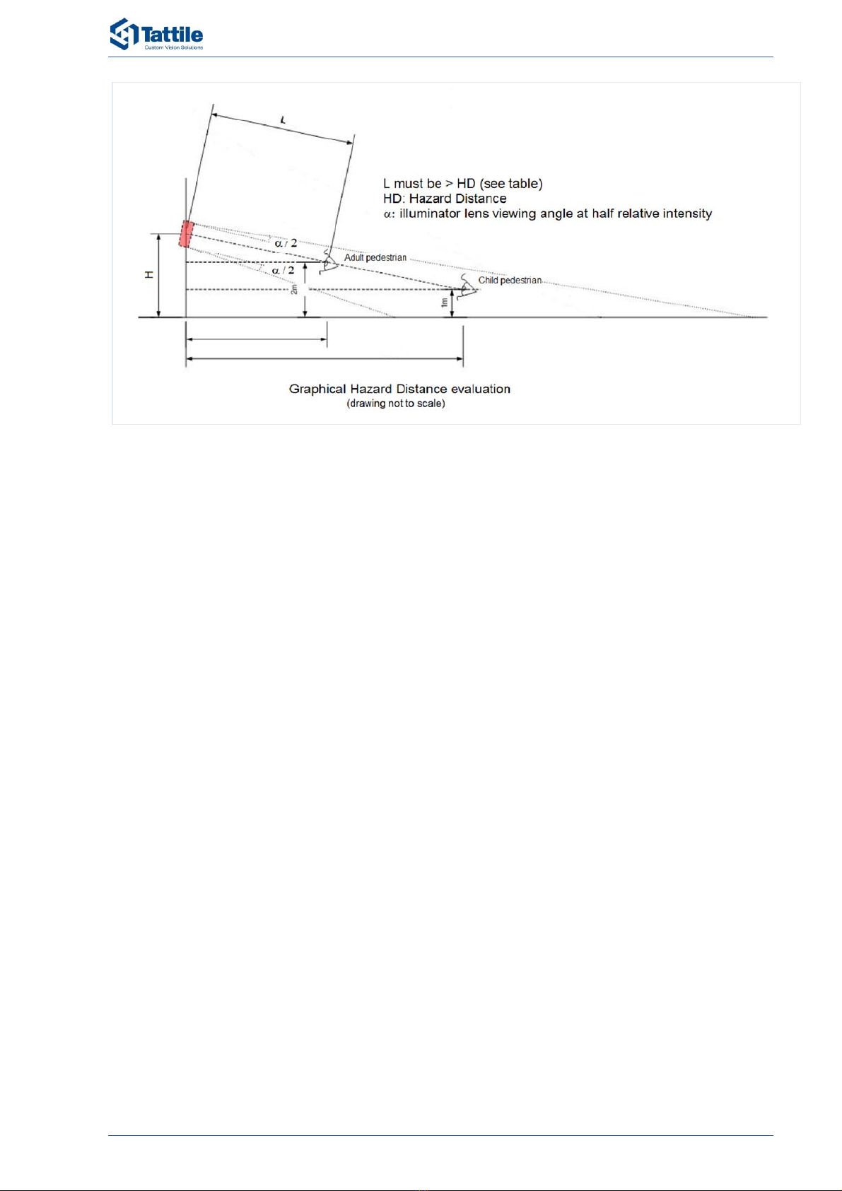
ForilluminatorexceedingExemptGrouplimitcamerashallbeinstalledasdetailedinthefigure
below,atdistanceL>HD,thereisnorisktothepublic.
Operatorormaintenancestaffworkinginfrontofthecamera,facingtheilluminator,atdistanceless
HDmustuseappropriateshieldingoreyeprotection,aswritteninthelabelling.
2Precautions/SafetyInstructions
RMM_00053_02 10 / 38 VEGA1 Series
Figure1:HazardDistanceevaluation
2.2 Intended Use of the Product
Theproductisdesignedforautomaticnumberplaterecognitionforthefollowingapplications:
– Singlelaneroadtracking.
– Surveillanceandaccesscontrol.
– Congestioncharge.
– Limitedtrafficareas,prioritylanes.
– Trafficmonitoring.
– Logisticandcustom.
2.3 Known or Foreseeable Misuse of the Product
Allotherusesnotincludedintheintendeduseoftheproductareconsideredasanimproperuseof
theproduct.

3GeneralCharacteristics
RMM_00053_02 11 / 38 VEGA1 Series
3 General Characteristics
3.1 Features
TheVEGA1isadualchannelcamerabuiltinacompactcase.
Itismainlytargetedtosinglelanevehicletracking,trafficlimitedareasandprioritylanes.Itshigh
sensitivityimagesensorsareavailableforANPRreading,videostreamingeveninextremeandlowlight
conditions.
Thecameraallowsaneasysetuptominimizetheinstallationandmaintenancetime.Thankstoitslocal
storageitcanoperatestand‐aloneincasetheconnectivityisnotavailable.
TheVEGA1iscompact,easytoinstallanddoesnotrequireanexternalIRlighting.Theextracompact
casereducesinstallationimpact.

3GeneralCharacteristics
RMM_00053_02 12 / 38 VEGA1 Series
3.2 Dimensions
3.2.1 Product Dimensions
Figure2showstheoverallviewoftheTattiledevice,dimensionsinmillimeters.
Figure2:TattileVEGA1dimensions

3GeneralCharacteristics
RMM_00053_02 13 / 38 VEGA1 Series
3.2.2 Wall-Mount Bracket Dimensions
Figure3showstheoverallviewofthewall‐mountbracket,dimensionsinmillimeters.
Figure3:Wall‐mountbracketdimensions

3GeneralCharacteristics
RMM_00053_02 14 / 38 VEGA1 Series
3.3 Physical Interface
3.3.1 Product Overview
Figure4:Productoverview
RefDescription
1OCRcamera(ANPRimage)
2Infraredilluminator
3Contextcamera(Overviewimage)
4Backcover
5Camerahousing
6Lenshood(sunshield)
7Mountingbracket
8GigabitEthernetconnector
9PowerSupply,SignalandI/Oconnector
10Productidentificationlabel

3GeneralCharacteristics
RMM_00053_02 15 / 38 VEGA1 Series
3.3.2 Power Supply, Signal and I/O Connector
Thetypeofthepowersupplyconnectoris:JamnutMale19‐pin.
Matingpartincludedinthepackage:
Figure5:Powersupply,signalandI/Oconnector
PINSignalnameDescription
AVIN‐ Powerinputground(GND)
BVIN‐ Powerinputground(GND)
CVIN+Powerinput+24Vdc
DVIN+Powerinput+24Vdc
EGNDSRS422/485serialportground
FIN0+Digitalinput0,positive(+)
GIN0÷1‐COMDigitalinput0÷1Commonnegative(‐)
HOUT0‐NORelayOutput0,NOcontact
JOUT0‐COMRelayOutput0,COMcontact
KSTRB0_OUTStrobeoutput0
LSTRB_GNDStrobeoutputcommonground
MEARTHFunctionalearth,devicechassis
NEARTHFunctionalearth,devicechassis
PNCNotconnected
RSER‐A(+)SerialportRS485A(+)
SSER‐B(‐)SerialportRS485B(‐)
TIN1+Digitalinput1,positive(+)
UOUT1‐NORelayOutput1,NOcontact
VOUT1‐COMRelayOutput1,COMcontact
Table4:Powersupply,signalandI/OInterface

3GeneralCharacteristics
RMM_00053_02 16 / 38 VEGA1 Series
Digital Input
FeatureDescription
TypeOptoisolatedPNP
Channels2(AuxiliaryConnector)
Voltage24Vdc
Table5:InputInterface
Figure6:Inputschematicsection
Relay Output
FeatureDescription
TypeNormallyopen
Channels2(AuxiliaryConnector)
Maxswitchingvoltage21Vac/30Vdc
Maxswitchingcurrent0.5A
Table6:OutputInterface
Figure7:Outputschematicsection

3GeneralCharacteristics
RMM_00053_02 17 / 38 VEGA1 Series
Strobe Output
FeatureDescription
TypeOptoisolatedopencollector
Channels1
Maxvoltage24Vdc+10%
Minvoltage3.3Vdc‐10%
Maxcurrent50mA
Table7:StrobeInterface
Figure8:Strobeschematicsection
3.3.3 Gigabit Ethernet Connector
ThetypeoftheGigabitEthernetconnectorisJamnutRJ‐45IP68.
Matingpartincludedinthepackage:
Figure9:GigabitEthernetconnector
PIN10/100mode(10base‐T/100base‐TX)Gigabitmode(1000base‐T)
1TX+MX0+
2TX‐ MX0‐
3RX+MX1+
4 MX2+
5 MX2‐
6RXMX1‐
7 MX3+
8 MX3‐
Table8:EthernetInterface

3GeneralCharacteristics
RMM_00053_02 18 / 38 VEGA1 Series
3.4 Technical Sheet / Specifications
General
VEGA‐1SeriesLONGSHORT
PartNumberF01870F01872
FlashMemorymicroSDcardupto128GB
RelayOutput2
StrobeOutput1
SerialPortInsulatedRS485
DigitalInputs2
LANGigabitEthernet10/100/1000
OperatingSystemLinux
RangeofactionUpto25mUpto8m
Lanedetected1
OthersSensor
IntegratedTill‐Rollsensor
Integratedtemperatureandhumiditysensor
Powersupplyvoltageandcurrentmonitoringsensor
Realtimeclock
GPSOptional
Wi‐FiOptional
OptionalFeatures
ModelRecognition
ClassRecognition
BrandRecognition
Colorrecognition
OCRImageSensor(ANPR)
Type1/1.8”CMOSMonochrome
Resolutionupto2048x1536activepixels
FrameRateUpto60
LensC‐Mount,withpreselectedfocallength
ContextImageSensor(Overview)
Type1/1.8”CMOSColor
Resolutionupto2048x1536activepixels
FrameRateUpto60
LensC‐Mount,withpreselectedfocallength
Illuminator
TypeInfrared,PeakWavelenght=860nm,Bandwidth30nm
Illum.beamangle(@
halfradialintensity)17°36°
NumberofLEDs10highpower

3GeneralCharacteristics
RMM_00053_02 19 / 38 VEGA1 Series
Electrical
PowerSupply24Vdc±10%
PowerConsumption20W(Max)
Startingcurrent3A(Max)
PoESupply
(PoweroverEthernet)PoE+802.3atType225W
Mechanical
Dimensions216mmx187mmx103.5mm(LxWxH)
CameraWeight2.5kg
Wall‐mountsupport
Weight0.6kg
HousingColorAnodizedAluminum
Environmental
OperatingandStorage
Temperature‐40°C÷+60°C
OperatingandStorage
HumidityUpto95%
ProtectionClassIP66,IP67
SWfeaturesand
Performance
Maxvehiclespeed200km/h
Detection99%
Reading>95%
OCRANPRonboardengine
2ndLevelOCRoptional
CapturerateUpto60fps
AES256Yes
SHA2Yes
CompressionJPG
Configuration
WebServerInstallationandconfigurationbyonboardWebServer
TCP/IPServerConfigurationandmonitoringthroughTCP/IPprotocol(SDKprovided)
DateandHourSynchronizationviaNTPprotocol,IEEE1588,GPS
SoftwareUpdateUpgradingviaWebInterfaceandSDK
Datatransmission
FTPFTPClienttoFTPServermodeforremotedatatransmission;MultipleIPserver
addressable
TCP/IPTattileTCP/IPopenprotocol(SDKprovided)
StandardProtocolsXML;SNMP;NTCIP;DATEX2;UTMC;MODBUS
Table9:TechnicalSheet/Specifications

3GeneralCharacteristics
RMM_00053_02 20 / 38 VEGA1 Series
3.5 Identification of the Product
Figure10:Productlabel
PartDescription
1Companylogo
2Productname
3MacAddressnumberbarcode(code128)
4MacAddressnumber
5Serialnumberbarcode(code128)
6Productserialnumber
7Productpartnumber
8CEmark
9Revision
10Ratedvoltageandcurrent,symbolfornatureofsupply
Table10:Productlabel
Table of contents
Other Tattile Digital Camera manuals


