Tattile GigE TAG-2 User manual

TAG-2
LINE-scan CAMERA
F00768 TAG-2 LCD 2048@9000 CLR
F00957 TAG-2 LBD 2048@18000 B/W
F01080 TAG-2 LCD 2048@9000 tCOMP CLR
F01081 TAG-2 LBD 2048@18000 tcomp B/W
Reference Manual
© 2009 Tattile S.r.l.
ENG

Version__03.02.00 (September 2009)
©2009 Tattile S.r.l.
All Tattile's systems were created to be alive, smart and open products. Therefore, we give you the chance to
update features and capabilities during the whole life cycle of the products. The Download area of our web site has
been created to allow our Partners to download new releases of Firmware and Software: http://www.tattile.com.
All material in this publication is subject to change without notice and is copyright Tattile S.r.l.

TAG-2 LINE-scan CAMERA
Index
Ordering codes.............................................................................................................................4
Mechanical dimensions................................................................................................................5
Connectors and indicators............................................................................................................6
General characteristics.................................................................................................................7
CCD general characteristics.........................................................................................................8
Interface connection...................................................................................................................10
Example of connection...............................................................................................................15
Accessories................................................................................................................................17
Installation instructions...............................................................................................................18
Warnings.....................................................................................................................................19
Revision history...........................................................................................................................20
3

TAG-2 LINE-scan CAMERA
Ordering codes
Ordering codes
Code Description Pixel Speed
(lines per second) Type Note
F00768 TAG-2 LCD 2048@9000 2048x3 9000 lps color
F00957 TAG-2 LBD 2048@18000 2048 18000 lps black/white
F01080 TAG-2 LCD 2048@9000 Tcomp 2048x3 9000 lps color With temperature
compensation
F01081 TAG-2 LBD 2048@18000 Tcomp 2048 18000 lps black/white With temperature
compensation
4
TAG-2 LINE-scan CAMERA
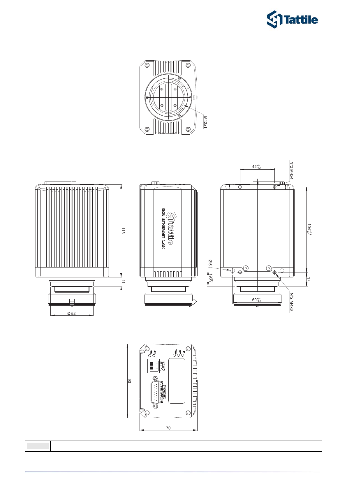
Mechanical dimensions
Note: Fix the camera with 4 M4 screws. Tightening torque 1,5 Nm.
5
TAG-2 LINE-scan CAMERA
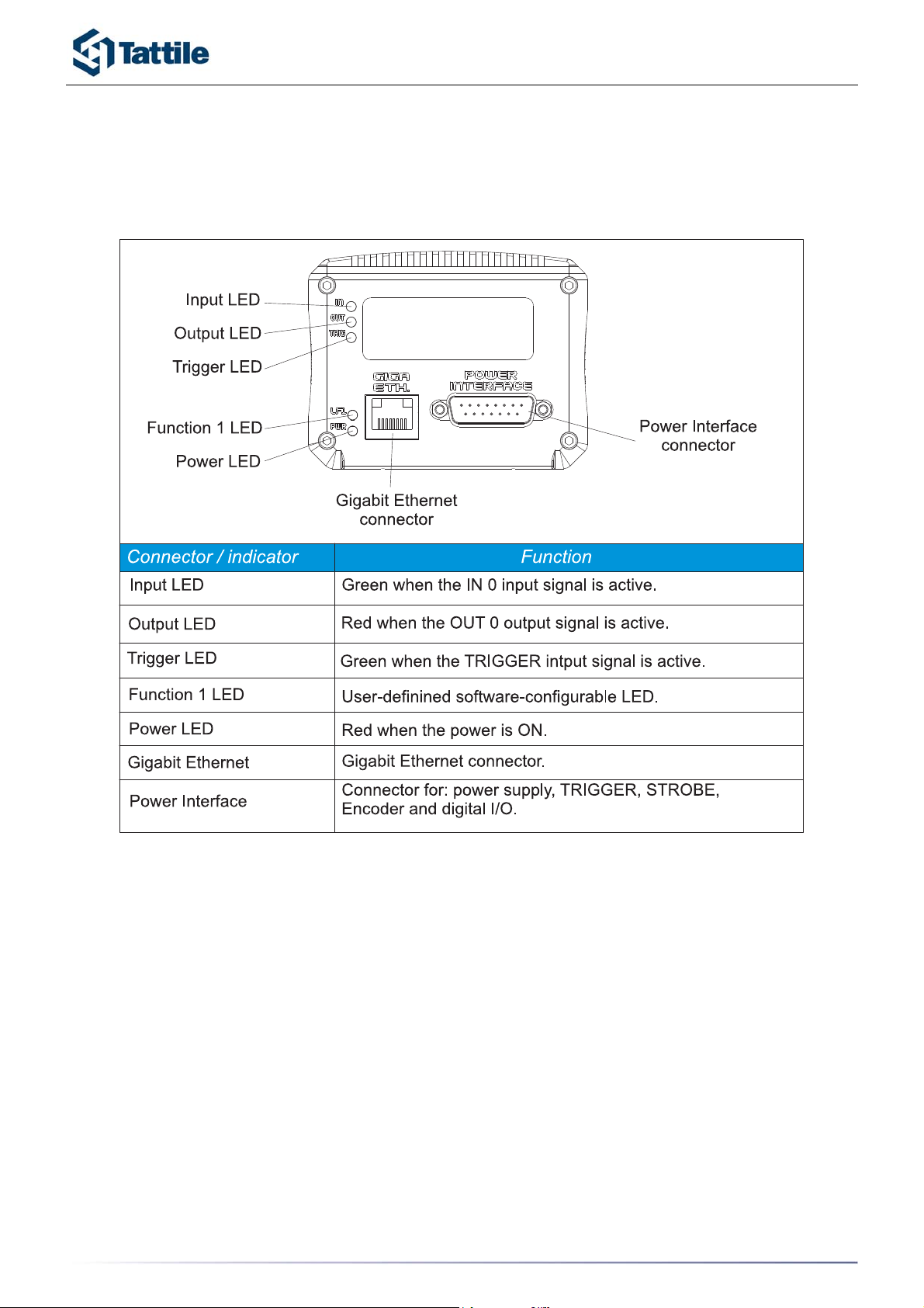
Connectors and indicators
Rear view
6

TAG-2 LINE-scan CAMERA
General characteristics
7
Characteristics
Electric Characteristics
Power Supply +24V
Power Consumption 9 W
Sensor Linear CCD sensor
IN 0 optoisolated digital input 24Vdc 20mA
TRIGGER digital input 24Vdc 20mA
minimum trigger pulse duration 5µsec
OUT 0 Optoisolated digital output 24Vdc 500mA
with overload and short-circuit protection
STROBE Open-collector digital output 24Vdc 50mA
Ethernet Network Gigabit Ethernet IEEE 802.3z
Processor
Microprocessor Altera NIOS FPGA Technology
Flash 8 Mb Flash Memory
SDRAM Micro 32 Mb
Mechanical Characteristics
Mechanical Dimensions 113 x 90 x70 mm (LxHxW)
Weight 900 gr (without lens)
Package Body Anodized Aluminium
Protection Degree IP42
Conformity Conform to CE Standards
Standard Supply
TAG-2 Camera
F-mount lens adapter
Reference Manual
Power supply voltage
Supply voltage +24Vdc +/- 10%
Ground 0V
Operating Conditions
Operating Temperature 0°C +50°C
Storage Temperature -10°C +65°C

TAG-2 LINE-scan CAMERA
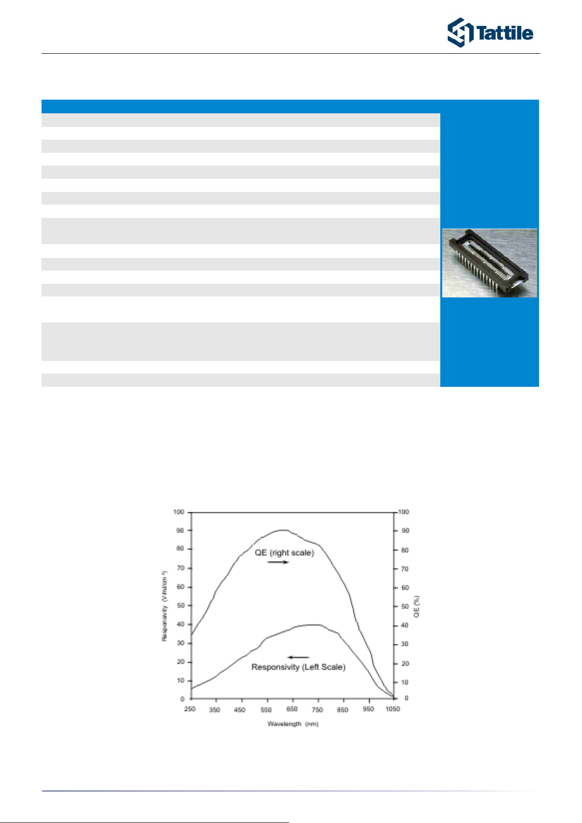
CCD general characteristics
CCD specifications (color)
Image sensor typical responsivity
8
Parameter Value
Architecture
3 Channel, RGB Ttrilinear
Pixel Count
2098x3
Pixel Size
14 µm (H) x 14 µm (V)
Pixel Pitch
14 um
Inter-Array Spacing
112 mm (8 lines effective)
Imager Size
29,37 mm (H) x 0,24 mm (V)
Saturation Signal
170,000 electrons
Dynamic Range
76 dB
Responsivity
(wavelenght=460, 540, 650 nm)
Output Sensitivity
Dark Current
0,02 pA/pixel
Dark Current Doubling Rate
9°C
Charge Transfer Efficiency
0,99999/Transfer
Photoresponse Non-uniformity
5% Peak-Peak
Lag (First Field)
0,60%
Maximum Data Rate
80 MB/s
Frame Rate
110 µs t0 3,2 ms
Shutter
Free-run, Edge controlled, Programmable
(external trigger)
Exposure Control
Gain
0:32 dB
Black Offset
0:255
Power Supply
24V
Consumption
9 W
15, 21, 37 V/µJ/cm
2
11,5 ųV/electron
1µs to 3,2 ms
TAG-2 LINE-scan CAMERA
CCD specifications (black/white)
Image sensor typical responsivity
9
Parameter Value
Architecture
Linear Photodiode Array
Pixel Count
2048
Pixel Size
14 µm (H) x 14 µm (V)
Pixel Pitch
14 um
Inter-Array Spacing
112 mm (8 lines effective)
Imager Size
29,37 mm (H) x 0,24 mm (V)
Saturation Signal
167,000 electrons
Dynamic Range
76 dB
Responsivity
(wavelenght=460, 540, 650 nm)
Output Sensitivity
Dark Current
0,02 pA/pixel
Dark Current Doubling Rate
9°C
Charge Transfer Efficiency
0,99999/Transfer
Photoresponse Non-uniformity
5% Peak-Peak
Lag (First Field)
1,50%
Pixel Rate
40MHz
Shutter
Free-run, Edge controlled, Programmable
(external trigger)
Exposure Control
yes
Dynamic Range
>2500:1
41 V/µJ/cm
2
6,6 ųV/electron

TAG-2 LINE-scan CAMERA
Interface connection
Power-interface connector
10

TAG-2 LINE-scan CAMERA
Input/output connections
11
TAG-2 LINE-scan CAMERA
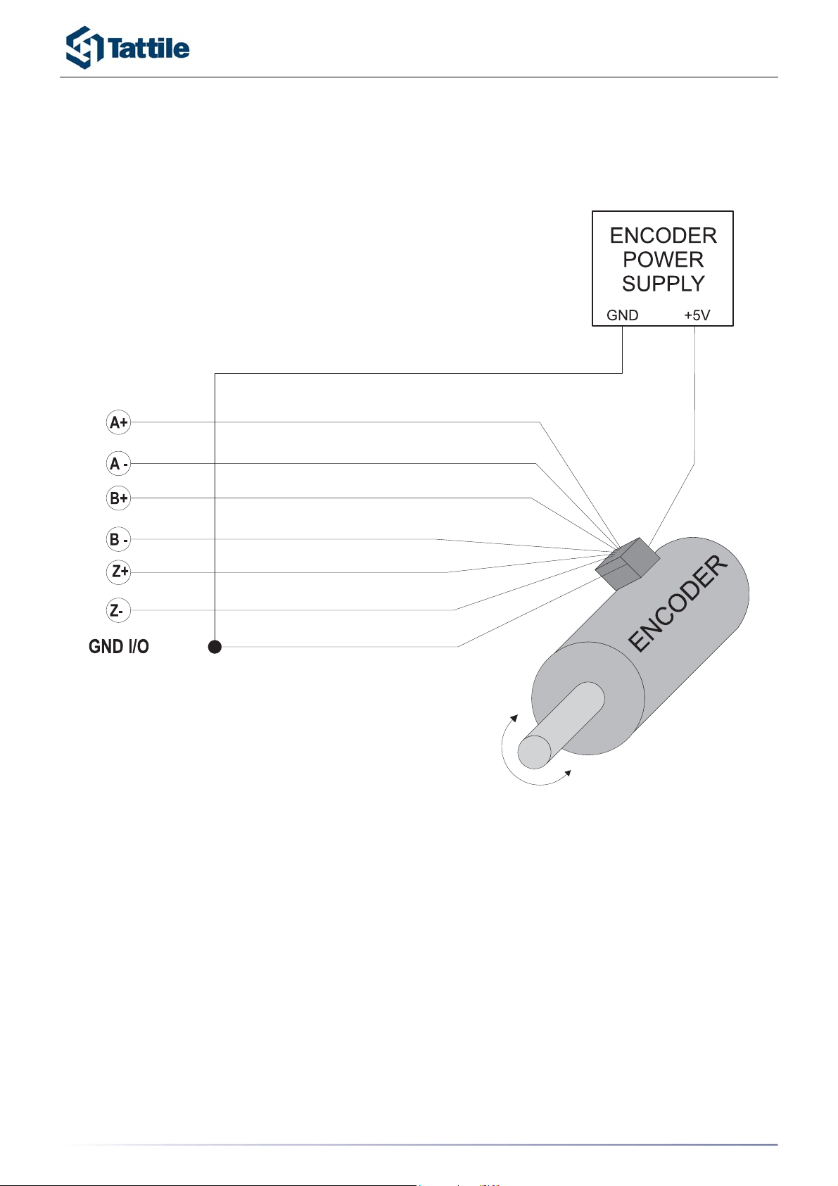
Encoder interface
The TAG-2 is able to manage a Line Drive encoder input for A/A– B/B- and Z/Z-
12
TAG-2 LINE-scan CAMERA
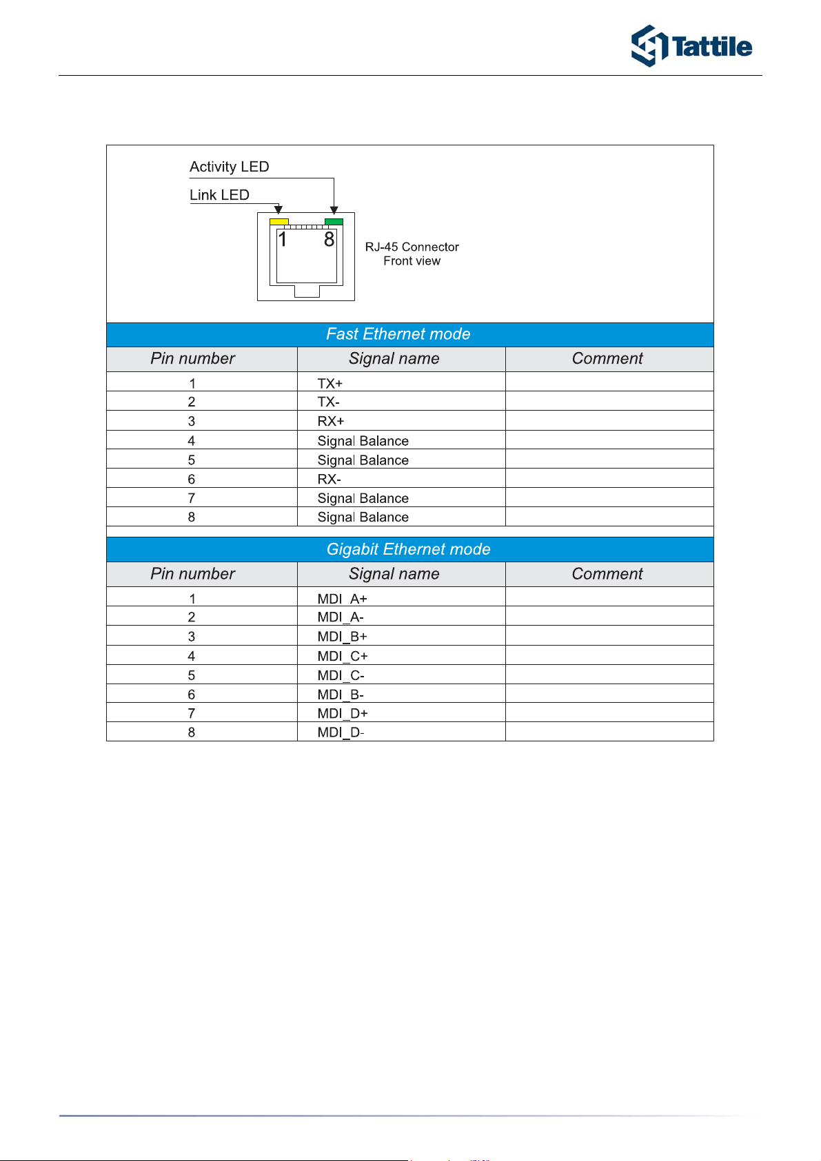
Ethernet connector
13

TAG-2 LINE-scan CAMERA
Ethernet connection cables
14

TAG-2 LINE-scan CAMERA
Example of connection
Standalone connection
The TAG-2 can be connected directly to a PC using an Ethernet cross-over cable. The PC can
be used to configure applications and monitor runtime operation. In this configuration, the
camera is isolated from the factory network.
Note: To connect the TAG-2 directly to a PC use a cross-over cable.
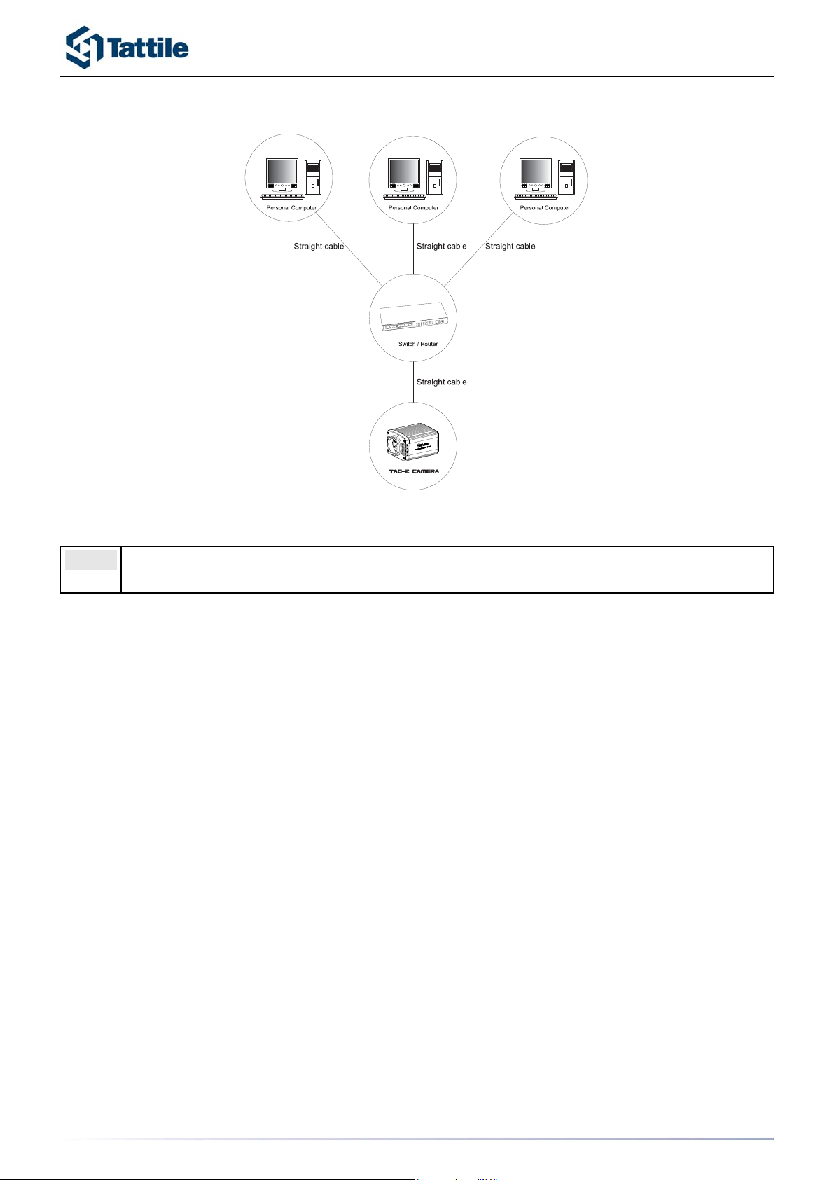
Connection using switches/routers
A maximum of 4 TAG-2 can be connected to a personal computer, using a network router or an
Ethernet switch.
Note: For connection between PC and switch/router and between switch/router and TAG-2
use Ethernet straight cables.
15
TAG-2 LINE-scan CAMERA
The TAG-2 can be connected to a network factory, using a network router or an Ethernet
switch.
Note: For connection between PC and switch/router and between switch/router and TAG-2
use Ethernet straight cables.
16

TAG-2 LINE-scan CAMERA
Accessories
Interface cable assembly (Ordering code: T07267)
Support (Ordering code: T11209)
17

TAG-2 LINE-scan CAMERA
Installation instructions
Good equipment operation is guaranteed only by respecting the instructions cited in this refer-
ence manual.
TATTILE declines all responsibility for anomalous equipment operation, installed with criteria
not respecting these instructions:
•TAG-2 cable courses must be kept separate from power cables.
•Pay attention to the various connections, especially in respect to the correct
polarity of the power-supply cables.
•Supply the TAG-2 with a dedicated power-supply.
•Mount the TAG-2 on a stable and vibration-free structure. Connect the TAG-2
chassis to the electrical earth (PE) with the mounting screw on the base of the
camera.
•The power supply cable must be screened and not longer than necessary.
•Do not disconnect the camera connector while the power is applied.
•Supply the main power (+Vpower and +0V) and the I/O power (+VI/O and
GNDI/O) with dedicated power supplies.
Do not supply power to the camera with a DC distribution system. (Max surge
1KV line-earth).
18

TAG-2 LINE-scan CAMERA
Warnings
The warranty covering Tattile equipment is invalidated when :
1. The equipment has been opened or tampered with.
2. Faults due to incorrect connection of power or input/output circuits.
3. Faults due to overload or non-compliance with equipment's rated specifications.
4. Application act in conditions that do not comply with those specified for a correct
installation.
Note: These conditions concern all equipment supplied with the system.
19

TAG-2 LINE-scan CAMERA
Revision history
The Revision Index is reported below. The various revisions can contain additional
information or corrections of printing errors.
Rev. Date Page Description Prepared Checked Approved
03.00.00 December
2005 --- First release N. Gilli G. Gualeni N. Franzelli
03.00.01 February
2008 8Corrected Pin2 Signal Name
Added Power Supply Cable design. Matteo B. G. Gualeni Nicola F.
03.01.00 April 2008 11,12 Added Encoder and Accessories
sections Matteo B. G. Gualeni Nicola F.
03.01.00 September
2009
7,11,
18
Added specifications about minimum
trigger pulse duration
Reviewed Connection Schematics at
page 11.
Added the installation note number 7.
Riccardi S. Forti P. Gualeni G.
20
Other manuals for GigE TAG-2
2
Table of contents
Other Tattile Digital Camera manuals


