Tavish Design Adagio Vacuum Tube Phono Stage User manual
TAVISH DESIGN,LLC
Made in U.S.A.
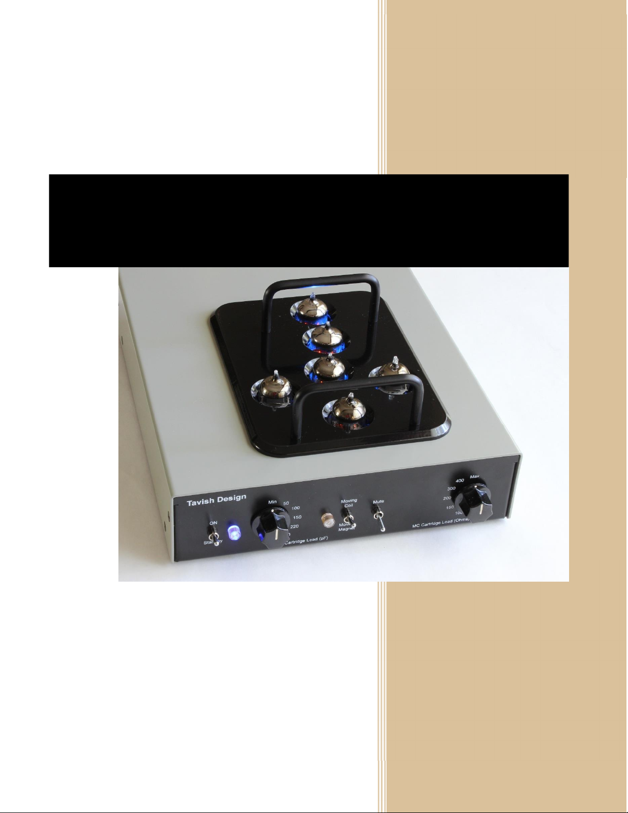
Adagio Vacuum Tube Phono Stage (MM / MC)
Owner’s Manual

1
TABLE OF CONTENTS
1. Introduction & Quick Start 2
2. Safety Considerations 3
3. Setup & Operation 4
3.1. Initial Setup
3.2. Operation
3.3. Tube Replacement
4. Technical Information 8
5. Warranty and Service 10
6. Copyright, Trademark, and Disclaimers 11
Manual Release 5 (21 November 2017)

2
1INTRODUCTION AND QUICK START
Thanks for buying the Adagio Phono Stage!
Tavish Design’s Adagio Vacuum-Tube Phono Stage is our top-of-the-line phono preamp, but at a
reasonable price, in a clean, simple package. It offers state-of-the-art specifications that rival or exceed
the measured performance of solid-state phono stages, but with an all-vacuum-tube signal path.
Vacuum tubes present some unique safety considerations, so please take time to read and understand
the safety considerations in Section 2 before using this equipment.
Quick Start
1. The tubes are installed before shipping, but check to be sure they are straight and fully seated. See
section 3 for tube locations.
2. Connect your turntable to either the Moving Magnet (MM) or Moving Coil (MC) input and set the
front panel toggle switch to the corresponding position. High impedance, high output MC cartridges
should connect to the MM input.
Select the appropriate loading for your cartridge. If you don’t know what loading to use, the 50 pf or
100 pF settings work well for most MM cartridges, and the “Max”setting works well for most MC
cartridges. Suggested loadings for some popular cartridges are given in Section 3, but feel free to
experiment.
Be sure to connect the ground post on the back of the phono stage to the ground post on your
turntable.
3. Connect the power cable from the power supply to the main phono stage. The connectors are
indexed and will only connect in one orientation. Turn the retaining ring on the power connectors
clockwise until you feel a “click”. The power supply can be placed in a convenient remote location
up to 6 feet from the main phono stage, but ensure that it has adequate ventilation.
4. Turn ON the power switches at BOTH the power supply and main phono stage. The power supply
can be left turned on and switched remotely from the ON-Standby switch on the main phono stage.
The phono stage takes approximately 45 seconds to warm up. Until then, the amber “Mute”LED on
the front panel will be lit and the phono stage will not pass signal.
The “Mute”switch can be used to mute the output when lowering or lifting the tonearm.
Turn down your volume control the first time you play an LP, until you are familiar with the
appropriate volume setting.

3
2SAFETY
1. To avoid the risk of electric shock, do not operate the amplifier without the top cover in
place. This amplifier uses high voltages internally which could cause an electrical shock,
possibly resulting in injury or death. Lethal voltages can remain in the electronics after the
unit is unplugged. Refer servicing to Tavish Design, LLC. If the unit must be opened for
servicing, unplug it and wait at least 10 minutes for internal capacitors to discharge.
2. Do not operate the amplifier without the vacuum tubes in place. Removal of the vacuum
tubes exposes internal circuity to contact and presents a shock hazard. This hazard is similar to
removing a light bulb from its socket.
3. Do not allow liquids (such as from a spilled drink or flower vase) to run into the amplifier, as
this can damage the amplifier or create an electric shock hazard. Do not operate outdoors or in
wet areas. Do not allow rain to enter the amplifier (by placing the unit next to an open window,
for instance).
4. A broken or improperly seated vacuum tube can cause electric shock. Do not operate the
amplifier if any vacuum tubes have broken glass shells. Align the tubes if any are leaning or not
fully seated, prior to operating the amplifier. Vacuum tubes get hot, so allow them to cool
before handling.
5. To avoid electric shock, do not insert thin metal objects between the vacuum tubes and the
cover, or allow children to do so. A metal object inserted into the amplifier could possibly
contact high voltages present internally. This hazard is similar to that of sticking a pin or thin
screwdriver into an electrical outlet.
6. Keep out of reach of children. In no case is line-operated electrical equipment child-safe.
Please keep children away from this product, as you would keep them away from an
incandescent light bulb, even when turned off.
7. The amplifier is designed to connect to a 3-wire grounded outlet. Never defeat the safety
ground on the amplifier; doing so can create an electric shock hazard. Please consult a
qualified electrician if you are in doubt about the grounding of your electrical system.
8. Worn or damaged electrical cables can present a shock hazard. Inspect electrical cables
regularly and replace them when they become worn or damaged. Please contact Tavish Design
for suitable replacements.

4
3SETUP
3.1 INITIAL SETUP
Setup consists of installing the tubes (if needed), connecting your turntable to the Moving Magnet (MM)
or Moving Coil (MC) input, setting the cartridge loading, connecting the Adagio output to your
preamplifier or integrated amplifier, and connecting the power supply.
Installing the Tubes
Fig. 3.1: Tube positions.
Note the tube positions above. To install the tubes, carefully align the tube pins with the socket and
push down, gently rocking the tube slightly from side-to-side to ease the pins into the socket. Never
twist or force the tube; the glass shell is easy to break if the pins are bent. See Section 3.3 for tube
removal and replacement. JJ 12AX7 / ECC83 are sometimes supplied in place of 5751, depending on
which low noise tubes we have in stock.
Connecting Your Turntable
The Adagio has separate inputs for Moving Magnet (MM) and Moving Coil (MC) cartridges. High
impedance, high output MC cartridges should connect to the MM input. The MM or MC input is selected
with the front panel switch. To avoid a loud transient, mute the output before adjusting the position of
12AU7
EF86
5751
Front
5751
5751
EF86

5
the switch or connecting or disconnecting cables. Be sure to connect the ground post on the back of the
phono stage to the ground post on your turntable.
The MC input on the Adagio is transformer balanced, and both XLR and RCA input connectors are
provided. A few turntables provide a balanced (XLR) output, which is preferred for its superior rejection
of external electromagnetic fields (such as from power lines in your house).
Cartridge Loading
Table 3.1 gives suggested settings for some popular cartridges. These are only a starting point. Follow
your cartridge manufacturer’s recommendations, or select the loading to suit your preference. In
selecting the capacitive load for a MM cartridge, note that the cables connecting your turntable to the
phono stage have approximately 30 –35 pF per foot, so a 3 foot cable contributes 100 pF of capacitance
to cartridge loading.
Cartridge
Type
Example
Reference
Output
Input
MM Load
MC Load
MM
AT95e
3.5 mV
MM
50 pF
N/A
MM
Ortofon 2M
5.5 mV
MM
50 pF
N/A
Low
-
Output
MC
Denon
DL103
0.35 mV
MC
N/A
Max (500
Ω)
Low
-
Output
MC
Ortofon
Quintet Red
0.5 mV
MC
N/A
300
Ω
Hi
-
Output
MC
Denon
DL110
1.6 mV
M
M
Min (No
added C)
N/A
Hi
-
Output
MC
Sumiko Blue
Point
2.5 mV
MM
Min (No
added C)
N/A
Table 3.1: Suggested settings for popular cartridges.
Connecting Your Preamplifier or Integrated Amplifier
The Adagio has a universal output which is compatible with both unbalanced RCA and balanced XLR
interconnect (pin 2 positive). If your preamplifier or integrated amplifier has a true balanced input, that
is the preferred input to use. Balanced XLR interconnects are used in professional equipment and can
reject hum which sometimes arises from interconnected equipment.

6
Connecting the Power Supply
Connect the 6 foot power cable from the power supply to the main phono stage. The connectors are
indexed and will only connect in one orientation. Turn the retaining ring on the power connectors
clockwise until you feel a “click”. The power supply can be placed in a convenient remote location up to
6 feet from the main phono stage, but ensure that the power supply has adequate ventilation, wherever
you place it. Longer power cables are available from Tavish Design.
The power supply is designed to connect to a 3-wire grounded outlet. Never defeat the safety ground on
the line cord; doing so can create an electric shock hazard. Please consult a qualified electrician if you
are in doubt about the grounding of your electrical system.
The power supply is interlocked and will not turn fully on unless the main phono stage is connected.
Worn or damaged electrical cables can present a shock hazard. Inspect electrical cables regularly and
replace them when they become worn or damaged. Please contact Tavish Design for suitable
replacements.
3.2 OPERATION
Turn ON the power switches at BOTH the power supply and main phono stage. The power supply can be
left turned on and switched remotely from the ON-Standby switch on the main phono stage.
The phono stage takes approximately 45 seconds to warm up. Until then, the amber “Mute”LED on the
front panel will be lit and the phono stage will not pass signal.
The “Mute”switch can be used to mute the output when lowering or lifting the tonearm.
Turn down your volume control the first time you play an LP, until you are familiar with the appropriate
volume setting.
3.3 TUBE REPLACEMENT AND SUBSTITUTION
Vacuum tubes last much longer than most people realize, and although the lifetime of any particular
tube is impossible to predict, hopefully it should be many years before any tube replacement is
necessary. Replace tubes with the same type. That is, replace the 12AU7A/ECC82 only with another
12AU7A/ECC82, not with another type. The only exception is the 5751, which can be replaced with a
12AX7A/ECC83 if you can’t find a 5751, or if you prefer the 12AX7.
The tubes are much easier to remove if you first remove the cover. Turn off and unplug the power
supply and wait 10 minutes for the internal high voltage capacitors to discharge. Remove the cover by

7
removing 4 screws on each side of the enclosure. Replace the cover after replacing the tubes. To avoid
a risk of electric shock, never operate the unit with the cover removed.
The unit is supplied with JJ and Electro-Harmonix tubes, but tubes of other manufacturers are also OK. It
is very unlikely that you will find a tube with lower noise than the JJ 5751 (if you do, please let us know).
New, old-stock (NOS) tubes tend to be noisier. The noise levels in the electronics are well below the
surface noise on vinyl LPs, so you may wish to choose the input tubes by other criteria as well.
Selected low noise JJ 5751s (or 12AX7 / ECC83S) are available from Tavish Design.

8
4TECHNICAL INFORMATION
Parameter
Specification
Gain
4
4 dB Moving Magnet
64 dB Low-Output Moving Coil (JT-44K-DX)
62 dB Low-Output Moving Coil (JT-347-AXT 1:8)
65 dB Low-Output Moving Coil (JT-347-AXT 1:12)
RIAA Equalization Accuracy
±0.
2
dB,
2
0 Hz
–
20 kHz
Signal
-
to
-
noise ratio
(A-weighted)
>
84
dBA ref. 5
mV @ 1kHz, Moving Magnet
>82 dBA ref. 0.5 mV @ 1kHz, Moving Coil
Reference Output
Level
75
0
mV RMS (0
dBu)
Total Harmonic Distortion
<0.0
08
% at referenc
e output level into
10
k
Ω,
1
kHz
Output Overload (defined as 1%
THD level)
>44
V RMS into 10 k
Ωat 1 kHz
(36
dB overload margin)
Input Impedance, Moving Magnet
47.5 k
Ωin parallel with
fixed capacitance of
approximately
20pF and adjustable capacitance of: 0pF, 50pF, 100pF, 150pF,
220pF, or 330pF
Input Impedance, Moving Coil
Adjustable:
500
Ω
(max), 400
Ω, 3
0
0
Ω, 2
00
Ω, 150 Ω, or 100
Ω
Output Impedance
10
0
Ω
at 1 kHz
Suggested Load
Impedance
≥
10
k
Ω
≤5000 pF (up to 150 feet of coaxial cable)
Tube Complement
5751 (x3), 6267/EF86 (x2), 12AU7A (x1)
Power
3
5
W, 120 VAC, 60 Hz
Main Phono Stage Size
8.6”wide, 10.2”deep, 2.2”high (3.9”high to top of tube guard)
Power Supply Size
8”
wide, 10.2”deep, 2.2”high
Weight
Phono Stage 4.6 lbs., Power Supply 3.1 lbs. (1
5
lbs. shipping
weight)
Table 4.1: Phono stage performance. Measurements are taken with JJ 5751, JJ (or Electro-Harmonix)
6267/EF86S, and JJ ECC82 tubes, as supplied. JJ 12AX7 / ECC83 are sometimes supplied in place of 5751,
depending on which low noise tubes we have in stock.
Tavish Design phono stages are designed to implement the traditional RIAA replay curve. We do not
implement the 1976 IEC Amendment which rolls off the replay response at 6dB/octave below 20Hz, and
we do not implement the occasionally discussed “Neumann pole”at 50 kHz. The 50 kHz pole is not part
of the RIAA standard.

9
Fig. 4.1: Typical measured RIAA equalization error, left and right channels. These are very small
equalization errors, and measurement error due to the test equipment itself is ±0.1 dB.
Fig. 4.2: Distortion spectrum, approximately 750 mV RMS output level at 1 kHz into 10 kΩ. This is
≤0.004% THD.
-1
-0.8
-0.6
-0.4
-0.2
0
0.2
0.4
0.6
0.8
1
10 100 1000 10000
RIAA Equalization Error, dB
Frequency, Hz
Measured RIAA Equalization Accuracy
Left
Right

10
5WARRANTY AND SERVICE
5.1 WARRANTY
With the exception of tubes, Tavish Design, LLC (hereinafter “Tavish Design”) warrants to the consumer
this product to be free of defects in materials or workmanship for a period of six (6) years from the date
of purchase (6 months on tubes). If you discover a defect, Tavish Design will (at its option) repair or
replace the product at no cost to you (excluding return shipping and handling outside the 48 continental
United States) provided that you send it prepaid to Tavish Design (see Section 5.2).
Proof of purchase in the form of a dated bill of sale which indicates that the product is within the
warranty period may be required to obtain warranty service, if the date of sale is not in our records.
This warranty does not cover cosmetic damage or any damage that results from product misuse,
product abuse, installation error, connection to an incorrect voltage supply, accident, improper
maintenance, alterations, modifications not authorized in writing by Tavish Design, lightening, power
surges, or acts of God. Use of parts not obtained from Tavish Design may void this warranty.
This warranty is limited to the replacement or repair of this product and not to damage to equipment of
other manufacturers. Any applicable implied warranties, including warranty of merchantability, are
limited in duration to a period of the express warranty as provided herein beginning with the original
date of purchase and no warranties, whether express or implied shall apply to the product thereafter.
Under no circumstances shall Tavish Design be liable for any loss, direct, indirect, incidental, special, or
consequential damage arising out of or in connection with the use of this product. Some states do not
allow limitations on how long an implied warranty lasts, and some states do not allow exclusion or
limitation of incidental or consequential damages, so some of the above limitations or exclusions may
not apply to you.
This warranty does not cover the cost of parts and labor which would be otherwise provided without
charge under this warranty, obtained from any source other than Tavish Design.
This warranty applies only to the consumer use of this product. The product is not warranted for use in
public address, sound reinforcement, in any trade or business, or in an industrial or commercial
application.
The warranty applies only to the original owner and is not transferrable.
This warranty is only valid in the United States of America. Units shipped outside the United States must
be returned to Tavish Design in the United States for warranty service.

11
5.2 SERVICE
Please contact Tavish Design for service (in or out of warranty) if you believe your amplifier needs repair.
Most technical issues can be resolved by email or phone. If your unit does require repair, we’ll issue a
return merchandise authorization (RMA) number, along with packing and shipping instructions and a
street address for delivery.
Tavish Design, LLC
P.O. Box 129
Amawalk, New York 10501
info@tavishdesign.com
914-262-6988
6COPYRIGHT,TRADEMARK,AND DISCLAIMERS
© Copyright Tavish Design, LLC 2017. All rights reserved. No part of this document may be reproduced
by any means or translated to other languages without prior written consent of Tavish Design, LLC.
Tavish Design® is a registered trademark of Tavish Design, LLC.
Tavish Design is continuously improving its products and reserves the right to make changes to its
products without incorporating those changes into previously sold units. The information provided here
is subject to change without notice. Tavish Design, LLC is not responsible for errors contained herein or
for consequential damages resulting from the use of this material.
Table of contents
Other Tavish Design Amplifier manuals


