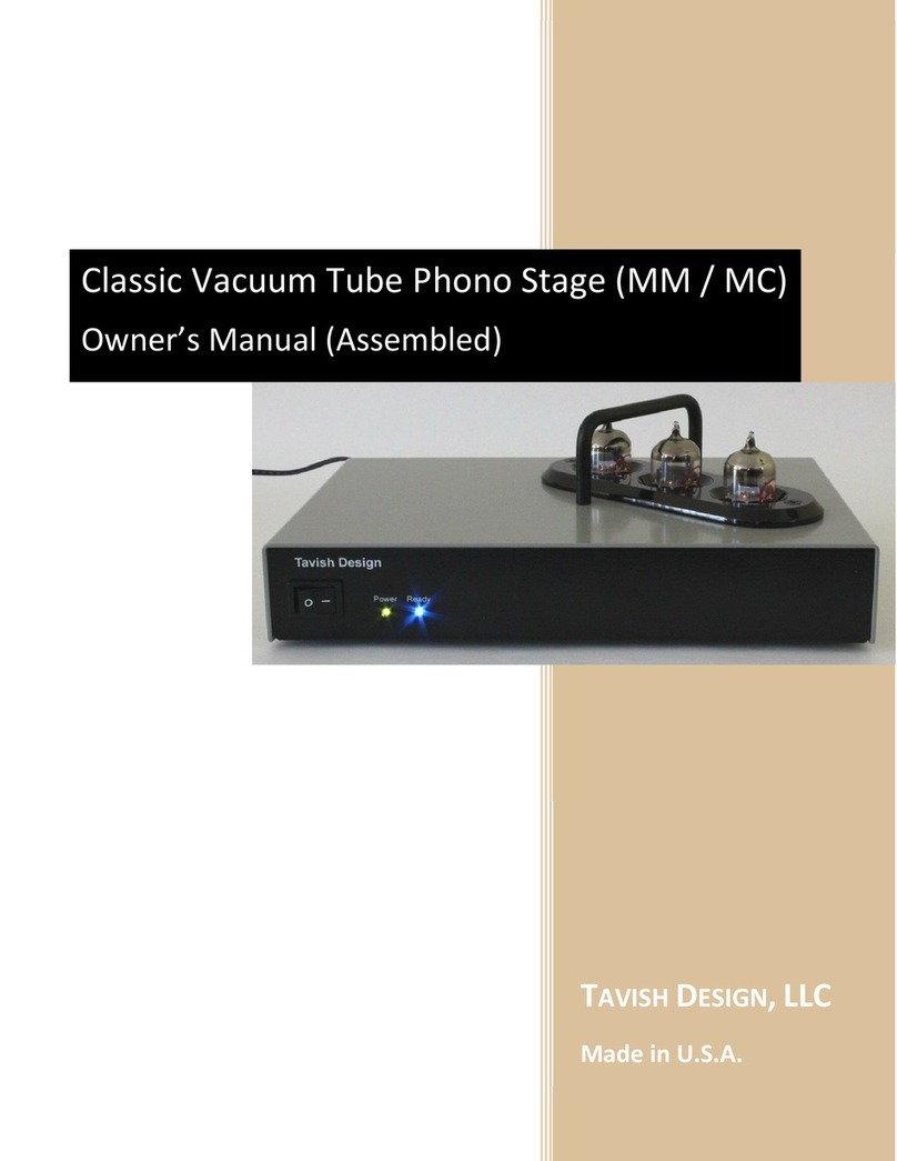
Tavish Design 6SL7 User guide

TAVISH DESIGN,LLC
Made in U.S.A.
Vintage 6SL7 Phono Stage (MM / MC)
Assembly and Setup Manual

1
TABLE OF CONTENTS
1. Introduction & Quick Start 2
2. Safety Considerations 3
3. Assembly 4
4. Setup & Operation 12
4.1. Initial Setup
4.2. Operation
4.3. Tube Replacement
5. Technical Information 16
5.1. Specifications
5.2. Schematics
5.3. Parts Placement Diagram
5.4. Parts Lists
6. Warranty and Service 29
7. Do-It-Yourself Guidance (FAQ) 30
8. Design Changes With Release 2.1 32
9. Copyright, Trademark, and Disclaimers 32
Manual Release 2.3a (17 February 2020)

2
1INTRODUCTION AND QUICK START
Thanks for buying the Vintage 6SL7 Phono Stage!
Tavish Design’s Vintage 6SL7 Phono Stage is a passively-equalized, two-gain-stage design using the 6SL7
octal dual triode, a vacuum tube first introduced (by RCA) in 1941, and one which has remained popular
with audio enthusiasts ever since. And, the basic circuit topology employed in our Vintage Phono Stage
has also remained popular for decades. The reason for the endurance of this straight-forward topology
is simple: with appropriate updates, it is very difficult to beat without going to elaborate multi-tube
circuits. In fact, this simple phono stage outperforms many (if not most) high-end products.
Vacuum tubes present some unique safety considerations, so please take time to look over the safety
considerations in Section 2.
Kit assembly instructions begin in Section 3. If you purchased the Vintage 6SL7 Phono Stage as an
assembled unit, please see the Quick Start instructions below.
Feel free to contact Tavish Design if you have any questions (info@tavishdesign.com).
Quick Start
1. Install the tubes. See Section 4 if you haven’t done this before.
2. Connect your turntable to either the Moving Magnet (MM) or Moving Coil (MC) input and set the
rear panel toggle switch to the corresponding position. Default settings for the Vintage Phono Stage
should work well with most MM and low-output MC cartridges. You can customize cartridge
loading, see Section 4.
If you have a high-output MC cartridge, the MM input is probably the best one to use, but it
depends on your cartridge output level, and you may want to adjust the internal cartridge loading
and gain settings. See Section 4.
Be sure to connect the ground post on the back of the phono stage to the ground post on your
turntable.
3. The phono stage takes 30 –40 seconds to warm up, as indicated by the blue “Ready”LED on the
front panel. The phono stage will not pass signal until then. Turn down your volume control the first
time you play an LP, until you are familiar with the appropriate volume setting.
6SL7GT
6SL7GT
6SL7GT
Front

3
2SAFETY
1. To avoid the risk of electric shock, do not operate the amplifier without the top cover in
place. This amplifier uses high voltages internally which could cause an electrical shock,
possibly resulting in injury or death. Lethal voltages can remain in the electronics after the
unit is unplugged. Refer servicing to Tavish Design, LLC. If the unit must be opened for
servicing, unplug it and wait at least 10 minutes for internal capacitors to discharge.
2. Do not operate the amplifier without the vacuum tubes in place. Removal of the vacuum
tubes exposes internal circuity to contact and presents a shock hazard. This hazard is similar to
removing a light bulb from its socket.
3. Do not allow liquids (such as from a spilled drink or flower vase) to run into the amplifier, as
this can damage the amplifier or create an electric shock hazard. Do not operate outdoors or in
wet areas. Do not allow rain to enter the amplifier (by placing the unit next to an open window,
for instance).
4. A broken or improperly seated vacuum tube can cause electric shock. Do not operate the
amplifier if any vacuum tubes have broken glass shells. Align the tubes if any are leaning or not
fully seated, prior to operating the amplifier. Vacuum tubes get hot, so allow them to cool
before handling.
5. To avoid electric shock, do not insert thin metal objects between the vacuum tubes and the
cover, or allow children to do so. A metal object inserted into the amplifier could possibly
contact high voltages present internally. This hazard is similar to that of sticking a pin or thin
screwdriver into an electrical outlet.
6. Keep out of reach of children. A high shelf or table is better than a low one, if children are
present.

4
3ASSEMBLY
Warning: This amplifier uses high voltages which could cause an electrical shock, possibly resulting in
injury or death. Therefore, these assembly instructions are intended for electronics technicians (or
those with equivalent skills) having experience with high-voltage electronics. The usual safety
procedures required when working with high voltages must be followed, and they are described only
briefly in these instructions. If you are unfamiliar with these procedures, you should not attempt
assembly. Please read through these instructions before beginning assembly. If you are in doubt
about your ability to safely and successfully assemble the kit, please send it back, or first get some
experience with other electronics kits. No liability is assumed by Tavish Design, LLC. The ARRL
Handbook for Radio Amateurs1has a useful chapter on electrical safety.
Kit assembly requires a soldering iron with a fine tip and a digital multimeter (DMM), along with other
normal electronics workshop tools.
Unpack the box and verify the following items:
Quantity
Item
1
Printed circuit board
(4 JFETs
are
pre
-
install
ed
on the PCB
in the complete kit
)
1
Enclosure
1
Decorative flange
1
Wall transformer
1
Bag of
5
8
metal film
resistors
1
Bag of 2
7
carbon film or metal oxide resistors, and trimmers
1
Bag of 2
0
electrolytic
capacitors
1
Bag of 19 film capacitors
1
Bag of
2
5
diodes, transistors, and ICs
(not including 4
JFETs
, which
are pre
-
install
ed)
1
Bag of
19
miscellaneous PCB
-
mounted components
3
Tube sockets
1
Bag of hardware and chassis
-
mounted components, including sw
itch and panel LEDs
3
Vacuum tubes (
Sovtek 6H9C/6SL7GT
)
1
PC mounted toroidal transformer
Detailed parts lists are included in tables 5.2 –5.6. Use the schematic, parts lists, and parts placement
diagram in section 5 to identify the correct location for parts.
1http://www.arrl.org/shop/ARRL-Handbook-2015-Softcover-Edition/

5
Step-by-step Instructions:
1. The surface mount JFETs are supplied pre-installed with the complete kit. If you purchased the
blank PCB, install the JFETs first. The 2SK209 are marked “XL”and the MMBFJ270 are marked
“61S”. Melt a small amount of solder on one of the pads. Then, holding the FET with a pair of
tweezers, re-melt the solder and place one leg of the JFET in the molten solder. Solder the other
two legs, then re-melt the solder for the first leg. Inspect the installation with a magnifying glass
to verify your solder joints.
2. Install the tube sockets. Align the socket’s index slot with the marking on the PCB, as show in
Photo 3.1. Double check the index alignment and make sure the sockets are fully seated against
the top of the PCB before soldering all pins.
Photo 3.1: PCB after step 2. Please note that this photo was taken prior to design revisions.
Photos 3.2 through 3.6 reflect the current PCB.
3. Install all resistors. Refer to http://www.resistorguide.com/resistor-color-code/ or
https://en.wikipedia.org/wiki/Electronic_color_code if you need help reading the color code on
1% resistors. It can be a good idea to place all the resistors on the PCB before soldering any of
them, to be sure you get them all in the right location. Don’t forget the jumpers R1, R8, R14,
R31, and R32: they are used to interconnect the separate ground domains on the PCB.

6
Photo 3.2: PCB after step 3.
4. Install Q2 and IC2-IC3 using a 3/8”#4-40 screw, flat washer, split washer, and nut to mount Q2
and IC2 (no flat washer needed for IC2) to the PCB before soldering. IC3 slides into heatsink HS1
and mounts upright.
5. Install D1 and D13 Zener diodes.
6. Install D7-D10 fast recovery diodes.
7. Install D3 Schottky diode.
8. Install D14-D15 1N4007.
9. Install D2, D4-D6 1N4002.

7
Photo 3.3: PCB after step 9.
10. Install trimmers R9 (500 Ω) and R23 (10 kΩ).
11. Install DIP sockets, noting that they have a polarity as marked on the PCB.
12. Install RLY1-RLY2, noting that they have a polarity as marked on the PCB.
13. Install the three PCB test points, a black one in the AGND pad, a red one in the HV pad, and a
yellow one in the P18 pad.
14. Install the rest of the small components, including transistors and capacitors, but not those
components that mount to the rear panel. Note the polarity of electrolytic capacitors and also
make sure that they are fully seated against the PCB.

8
Photo 3.4: PCB after step 14.
15. Install J1-J3, SW1, and U1. For J1-J2, remove the chrome cover to expose the black insulator
underneath before installing. This prevents the signal ground from shorting to the chassis (they
must be isolated to prevent ground loops). See photo 3.5 below. Solder only one leg of each
component, making sure they are seated against the PCB, then test fit the PCB in the enclosure.
Adjust the position of the rear panel components if needed and solder fully in place.
Photo 3.5: Switchcraft RCA connectors with chrome cover removed.

9
16. Prepare a 22ga. wire 2¾”(7 cm) long to connect the PCB wirepad CHASSIS to the rear panel
ground post, using the ¼-20 ground terminal. Prepare a 22 ga. twisted pair 5½”(14 cm) long to
connect the wirepads PS1 and PS2 to the front panel rocker switch, using 0.187”quick connect
terminals.
17. Prepare a 24 ga. red/black twisted pair 3”(7.5 cm) long with one red wire connected to the RMC
pad and one black wire connected to the RG pad. The other end will be trimmed to length later.
Prepare a 24 ga. white/black twisted pair 3”long with one white wire connected to the LMC pad
and one black wire connected to the LG pad. The other end will be trimmed to length later.
18. Install the power transformer using a 3/8”#6-32 screw, nylon flat washer, and #6-32 split
washer, and solder in place.
19. Install IC1 and IC5, and the fuse.
20. Install the eight ¼”long nylon hex spacers on the bottom of the PCB, using #6-32 nylon hex nuts
on the top of the PCB.
Photo 3.6: Completed PCB after step 20.
21. Double check that you have installed the components into their correct locations, and in the
appropriate orientation, according to photo 3.6 above. Check that all PCB connections have
been soldered. Set S1-S3 into their “factory default”positions according to tables 4.1 –4.3
below and photo 3.8 below.
22. Install the PCB into the enclosure base using eight ¼”nylon screws from the bottom, one #6-32
black oxide pan head screw from the back, and two #3-24 plastite screws for the RCA jacks.
23. Install 4 rubber feet and the serial number sticker on the bottom of the unit.
24. Install the white RCA jack in the lower chassis hole for the moving coil input. Make sure it is
insulated from the chassis using the nylon shoulder washer and flat washer. Connect the
white/black twisted pair (white to the center signal terminal), keeping the wires as short as

10
possible and twisted as tightly as possible. Bend the ground lug toward body of the connector as
shown in the assembly detail in photo 3.7.
Photo 3.7: Connector wiring assembly detail.
25. In a similar manner, install and wire the red RCA jack in the upper chassis hole for the moving
coil input (red to the center signal terminal).
26. Install and connect the ground post.
27. Install and connect the rocker switch.
28. Install the front panel LEDs, connecting the wires from the green LED to the “LED3”pads and the
wires from the blue LED to the “LED”pads, red to the (+) pad and black to the (-) pad.
29. Install the decorative flange to the top of the enclosure using 1/4”#6-32 pan head screws and
split washers.

11
Photo 3.8: Completed phono stage after step 29.
30. Install the tubes (see section 4.1 below). Connect the negative lead of your voltmeter to the
black PCB test point installed at the AGND pad. Connect the positive lead of your voltmeter to
the P18 pad using the yellow PCB test point installed there. Observing appropriate high voltage
safety procedures (such as keeping one hand in your pocket while the unit is powered on), plug
in the wall transformer and switch the unit on. Measure the voltage at the P18 pad and adjust
trimmer R9 for +18.6 V. Turn off the power and wait 10 minutes for the capacitors to discharge.
31. Connect the positive lead of your voltmeter to the HV pad using the red test point installed
there. Measure the voltage at the HV pad and adjust trimmer R23 for +210 V. Turn off the
power and wait 10 minutes for the capacitors to discharge.
32. Install the High Voltage sticker on the top of the transformer.
33. Install the cover using four ¼”#6-32 black oxide flat head screws (which are shipped installed in
the enclosure). This completes assembly.

12
4SETUP
4.1 INITIAL SETUP
Setup consists of installing the tubes (if needed), selecting the Moving Magnet (MM) or Moving Coil
(MC) input, and setting the cartridge loading and MC gain (if needed). The factory settings for these
should work well with most MM cartridges, and with low-output MC cartridges, so you might not need
to adjust anything.
Installing the Tubes
Fig. 4.1: Tube positions.
Note the tube positions above. To install the tubes, carefully align the tube’s center index key with the
socket and push down, gently rocking the tube slightly from side-to-side to ease the pins into the socket.
Never twist or force the tube; the glass shell is easy to break if the pins are bent. The tubes are much
easier to remove if the cover is removed first. Before removing the cover, unplug the unit and wait 10
minutes for the internal capacitors to discharge. Remove the cover by removing 4 screws.
Moving Magnet or Moving Coil Input
MM cartridges connect to the MM input (obviously), and low-output MC cartridges connect to the MC
input.
In general, we recommend that high-output MC cartridges with an output >2 mV be connected to the
MM input. We recommend that high-output MC cartridges with outputs <2 mV be connected to the MC
input, with low gain setting, as described below. However, almost all high-output MC cartridges can also
connect to the MM input if you prefer (and if there is enough gain for your system).
The MM or MC input is selected with SW1 on the back. To avoid a loud transient, turn the volume
control on your amplifier to minimum before adjusting the position of SW1 or connecting or
disconnecting cables. Be sure to connect the ground post on the back of the phono stage to the ground
post on your turntable.
6SL7GT
6SL7GT
6SL7GT
Front

13
Cartridge Loading and Moving Coil Gain
Cartridge loading and the MC gain setting are set with internal DIP switches. The factory settings for
these should work well with most MM cartridges, and with low-output MC cartridges. To select other
settings, unplug the unit and wait 10 minutes for the internal capacitors to discharge. Remove the cover
by removing 4 screws. Note the positions of DIP switches S1 –S3 as shown in Fig. 4.2 below. The tables
4.1 to 4.3 below show the switch positions to select other MC gain and cartridge load settings. Table 4.4
gives suggested settings for some popular cartridges. These are only a starting point. Follow your
cartridge manufacturer’s recommendations, or select the loading to suit your preference. In selecting
the capacitive load for a MM cartridge, note that the cables connecting your turntable to the phono
stage have approximately 30 –35 pF per foot, so a 3 foot cable contributes 100 pF of capacitance to
cartridge loading.
Replace the cover after setting the cartridge loading and gain switches. To avoid a risk of electric
shock, never operate the unit with the cover removed.
Fig. 4.2: Switch positions for setting MC Gain (S3), MC load (S2), and MM load (S1). For each switch, LEFT
= OFF = 0, and RIGHT = ON = 1.
MC Gain Setting (S3)
S3 Positions (1
–
2)
OFF = 0, ON = 1
High (6
1
dB)
00
Factory Default
Low (5
3
dB)
11
Table 4.1: MC Gain Settings.

14
MM Load Setting (S2)
S2 Positions (1
–
7) OFF = 0, ON = 1
No added capacitance
0001000
47 pF
1001100
Factory Default
100 pF
0101010
147 pF
1101110
180 pF
0011001
227 pF
1011101
280 pF
0111011
327 pF
1111111
Table 4.2: MM Load Settings.
MC Load Setting (S1)
S1 Positions (1
–
7) OFF = 0, ON = 1
47.5 k
Ω
0001000
1 k
Ω
0011001
Factory Setting
330
Ω
0101010
250
Ω
0111011
100
Ω
1001100
91
Ω
1011101
77
Ω
1101110
71
Ω
1111111
Table 4.3: MC Load Settings.
Cartridge
Type
Example
Reference
Output
Input
MC Gain
Setting (S3: 1 –2)
MM Load
(S2: 1 –7)
MC Load
(S1: 1 –7)
MM
AT95e
3.5 mV
MM
N/
A
47 pF
1001100
N/
A
MM
Ortofon 2M
5.5 mV
MM
N/
A
47 pF
1001100
N/
A
Low
-
Ou
t
put
MC
Denon
DL103
0.35 mV
MC
High (00)
N/
A
1 k
Ω
0011001
Low
-
Output
MC
Ortofon
Quintet Red
0.5 mV
MC
High (00)
N/A
330
Ω
0101010
Hi
-
Output
MC
Denon
DL110
1.6 mV
MC
Low (11)
N/
A
47.5 k
Ω
0001000
Hi
-
Output
MC
Sumiko Blue
Point
2.5
mV
MM
N/A
No added C
0001000
N/A
Table 4.4: Suggested settings for popular cartridges. Note that the first three rows use the factory
default settings.

15
4.2 OPERATION
If you removed the cover to adjust to set the cartridge loading and gain switches, you must replace it
before operating the unit. To avoid a risk of electric shock, never operate the unit with the cover
removed.
When the unit is switched on, it goes through a 40 second warmup sequence before the blue “ready”
LED turns on. The phono stage will not pass signal until the blue “ready”LED is on. Before playing an LP,
turn down the volume control on your amplifier until you are familiar with the required gain setting.
4.3 TUBE REPLACEMENT AND SUBSTITUTION
Vacuum tubes last much longer than most people realize, and although the lifetime of any particular
tube is impossible to predict, hopefully it should be many years before any tube replacement is
necessary. Replace tubes with the same type: only 6SL7GT tubes can be used in the phono stage. In
particular, many people confuse the 6SL7 with the 6SN7. Unfortunately, the 6SN7 cannot be used in any
position in the phono stage.
The unit is normally supplied with either Sovtek 6H9C/6SL7GT or Tung Sol Reissue 6SL7GT tubes. It is
also OK to use new, old-stock (NOS) 6SL7GT tubes in the phono stage, although they do tend to be
noisier, so you should be aware of potentially higher noise if you do use them. Noise is primarily an issue
with the input tube (the right front tube). The noise levels in the electronics are well below the surface
noise on vinyl LPs, so you may wish to choose the input tube by other criteria as well.
The tubes are much easier to remove if the cover is removed first. Before removing the cover, unplug
the unit and wait 10 minutes for the internal capacitors to discharge. Remove the cover by removing 4
screws on the sides of the enclosure. If you do remove the cover, you must replace it before operating
the unit. To avoid a risk of electric shock, never operate the unit with the cover removed.

16
5TECHNICAL INFORMATION
Parameter
Specification
Gain
4
1
dB Moving Magnet
53 dB High-Output Moving Coil
61 dB Low-Output Moving Coil
RIAA Equalization Accuracy
±0.
5
dB,
25
Hz
–
20 kHz
Signal
-
to
-
noise ratio
(A-weighted)
>
79
dBA ref. 5
mV @ 1kHz, Moving Magnet
>79 dBA ref. 1.25 mV @ 1kHz, High-Output Moving Coil
>76 dBA ref. 0.5 mV @ 1kHz, Low-Output Moving Coil
Reference Output Level
56
0
mV RMS (
-
2
.8 dBu)
Total Har
monic Distortion
<0.0
2
% at referenc
e output level into
22
k
Ω,
1
kHz
Output Overload (defined as 1%
THD level)
>1
4
V RMS into
22
k
Ωat 1 kHz
(31dB overload margin)
Input Impedance, Moving Magnet
47.5 k
Ωin parallel with
fixed capacitance of
approximately
85pF and adjustable capacitance of: 0pF, 47pF, 100pF, 147pF,
180pF, 227pF, 280pF, or 327pF
Input Impedance, Moving Coil
Adjustable: 47.5 k
Ω, 1 kΩ, 330 Ω, 250 Ω, 100 Ω, 91 Ω, 77Ω, or
71 Ω
Output Impedance
<
100
0
Ω
at 1 kHz
Suggested Load Impedance
≥10 kΩ
≤1800 pF (up to 60 feet of coaxial cable)
Power
18 W, 120 VAC, 60 Hz
Size
9”wide x 6”deep x 1.5”high (
4
”high to top of tube guard)
Weight
3.5 pounds (6
pounds shipping weight)
Table 5.1: Phono stage performance. Measurements are taken with Sovtek 6H9C/6SL7GT tubes, as
supplied.

17
Fig. 5.1: Typical measured RIAA equalization error with both Sovtek 6H9C/6SL7GT (ST) and Tung Sol
Reissue 6SL7GT (TS) tubes, left and right channels. Error is <0.5 dB from 25 Hz –20 kHz for all curves.
Fig. 5.2: Typical measured distortion over frequency, 560 mV RMS output level into 22 kΩ. ST =
Sovtek 6H9C/6SL7GT, TS = Tung Sol Reissue 6SL7GT
-1
-0.8
-0.6
-0.4
-0.2
0
0.2
0.4
0.6
0.8
1
10 100 1000 10000
RIAA Equalization Error, dB
Frequency, Hz
Measured RIAA Equalization Accuracy
R1(ST)
L1(ST)
R2(TS)
L2(TS)
0.001
0.01
0.1
1
10 100 1000 10000
Total Harmonic Distortion, %
Frequency, Hz
Measured THD vs. Frequency
R1(ST)
L1(ST)
R2(TS)
L2(TS)

18
Fig. 5.3: Schematic, sheet 1 of 4

19
Fig. 5.4: Schematic, sheet 2 of 4
Table of contents
Other Tavish Design Amplifier manuals
Popular Amplifier manuals by other brands
EMPHASER
EMPHASER EA13000SPL Installation & operating manual
Audio Control
Audio Control ARCHITECT P250 EQ installation manual
Audio Valve
Audio Valve ASSISTENT 30 manual

Oldfield Amplifiers
Oldfield Amplifiers Troubadour user guide

AVPro Edge
AVPro Edge AC-DA14-AUHD user manual

BOSSCO
BOSSCO Acoustic Singer Live user manual
