Tavish Design MM series User manual

TAVISH DESIGN,LLC
Made in U.S.A.
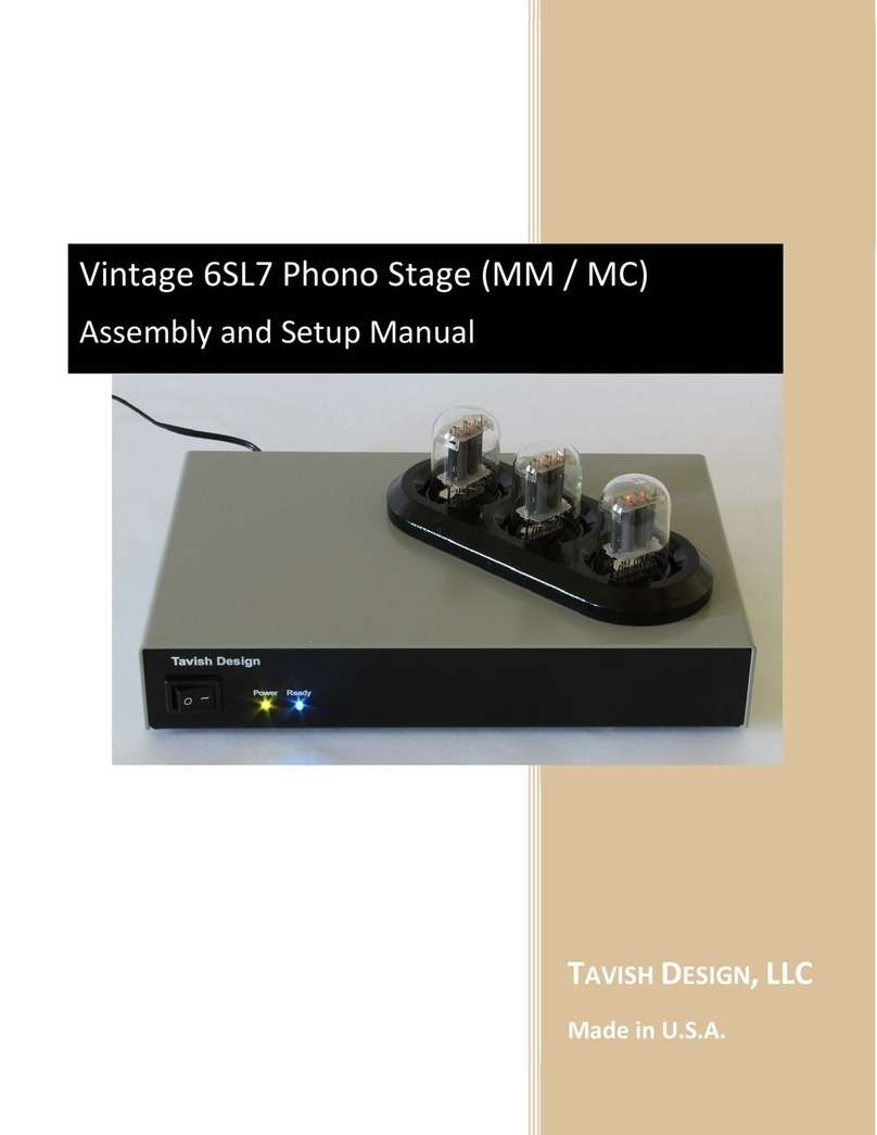
Classic Vacuum Tube Phono Stage (MM / MC)
Owner’s Manual (Assembled)

1
TABLE OF CONTENTS
1. Introduction & Quick Start 2
2. Safety Considerations 3
3. Setup & Operation 4
3.1. Initial Setup
3.2. Operation
3.3. Tube Replacement
4. Technical Information 8
5. Warranty and Service 10
6. Copyright, Trademark, and Disclaimers 11
Manual Release 5.1A (15 Jan. 2016)

2
1INTRODUCTION AND QUICK START
Thanks for buying the Classic Phono Stage!
Tavish Design’s Classic Vacuum-Tube Phono Stage is a passively-equalized, two-gain-stage design whose
basic circuit topology has remained popular for more than 55 years. The reason for its endurance is
simple: with appropriate updates, it is very difficult to beat without going to elaborate multi-tube
circuits. In fact, this simple phono stage outperforms many (if not most) high-end products.
Vacuum tubes present some unique safety considerations, so please take time to look over the safety
considerations in Section 2.
Quick Start
1. Install the tubes. See Section 3 if you haven’t done this before.
2. Connect your turntable to either the Moving Magnet (MM) or Moving Coil (MC) input and set the
rear panel toggle switch to the corresponding position. Default settings for the Classic Phono Stage
should work well with most MM and low-output MC cartridges. You can customize cartridge
loading, see Section 3.
If you have a high-output MC cartridge, the MM input is probably the best one to use, but it
depends on your cartridge output level, and you may want to adjust the internal cartridge loading
and gain settings. See Section 3.
Be sure to connect the ground post on the back of the phono stage to the ground post on your
turntable.
3. The phono stage takes 30 –40 seconds to warm up, as indicated by the blue “Ready”LED on the
front panel. The phono stage will not pass signal until then.
Turn down your volume control the first time you play an LP, until you are familiar with the
appropriate volume setting.
12AU7
12AX7
5751
Front

3
2SAFETY
1. To avoid the risk of electric shock, do not operate the amplifier without the top cover in
place. This amplifier uses high voltages internally which could cause an electrical shock,
possibly resulting in injury or death. Lethal voltages can remain in the electronics after the
unit is unplugged. Refer servicing to Tavish Design, LLC. If the unit must be opened for
servicing, unplug it and wait at least 10 minutes for internal capacitors to discharge.
2. Do not operate the amplifier without the vacuum tubes in place. Removal of the vacuum
tubes exposes internal circuity to contact and presents a shock hazard. This hazard is similar to
removing a light bulb from its socket.
3. Do not allow liquids (such as from a spilled drink or flower vase) to run into the amplifier, as
this can damage the amplifier or create an electric shock hazard. Do not operate outdoors or in
wet areas. Do not allow rain to enter the amplifier (by placing the unit next to an open window,
for instance).
4. A broken or improperly seated vacuum tube can cause electric shock. Do not operate the
amplifier if any vacuum tubes have broken glass shells. Align the tubes if any are leaning or not
fully seated, prior to operating the amplifier. Vacuum tubes get hot, so allow them to cool
before handling.
5. To avoid electric shock, do not insert thin metal objects between the vacuum tubes and the
cover, or allow children to do so. A metal object inserted into the amplifier could possibly
contact high voltages present internally. This hazard is similar to that of sticking a pin or thin
screwdriver into an electrical outlet.
6. Keep out of reach of children. A high shelf or table is better than a low one, if children are
present.

4
3SETUP
3.1 INITIAL SETUP
Setup consists of installing the tubes (if needed), selecting the Moving Magnet (MM) or Moving Coil
(MC) input, and setting the cartridge loading and MC gain (if needed). The factory settings for these
should work well with most MM cartridges, and with low-output MC cartridges, so you might not need
to adjust anything.
Installing the Tubes
Fig. 3.1: Tube positions.
Note the tube positions above. To install the tubes, carefully align the tube pins with the socket and
push down, gently rocking the tube slightly from side-to-side to ease the pins into the socket. Never
twist or force the tube; the glass shell is easy to break if the pins are bent.
Moving Magnet or Moving Coil Input
MM cartridges connect to the MM input (obviously), and low-output MC cartridges connect to the MC
input.
In general, we recommend that high-output MC cartridges with an output >2 mV be connected to the
MM input. We recommend that high-output MC cartridges with outputs <2 mV be connected to the MC
input, with low gain setting, as described below. However, almost all high-output MC cartridges can also
connect to the MM input if you prefer (and if there is enough gain for your system).
The MM or MC input is selected with SW1 on the back. To avoid a loud transient, turn the volume
control on your amplifier to minimum before adjusting the position of SW1 or connecting or
disconnecting cables. Be sure to connect the ground post on the back of the phono stage to the ground
post on your turntable.
12AU7
12AX7
5751
Front

5
Cartridge Loading and Moving Coil Gain
Cartridge loading and the MC gain setting are set with internal DIP switches. The factory settings for
these should work well with most MM cartridges, and with low-output MC cartridges. To select other
settings, unplug the unit and wait 10 minutes for the internal capacitors to discharge. Remove the cover
by removing 4 screws. Note the positions of DIP switches S1 –S3 as shown in Fig. 3.2 below. The tables
3.1 to 3.3 below show the switch positions to select other MC gain and cartridge load settings. Table 3.4
gives suggested settings for some popular cartridges. These are only a starting point. Follow your
cartridge manufacturer’s recommendations, or select the loading to suit your preference. In selecting
the capacitive load for a MM cartridge, note that the cables connecting your turntable to the phono
stage have approximately 30 –35 pF per foot, so a 3 foot cable contributes 100 pF of capacitance to
cartridge loading.
Replace the cover after setting the cartridge loading and gain switches. To avoid a risk of electric
shock, never operate the unit with the cover removed.
Fig. 3.2: Switch positions for setting MC Gain (S3), MM load (S2), and MC load (S1). For each switch, LEFT
= OFF = 0, and RIGHT = ON = 1.
MC Gain Setting (S3)
S3 Positions (1
–
2) OFF = 0, ON = 1
High (6
1
dB)
00
Factory Default
Low (5
3
dB)
11
Table 3.1: MC Gain Settings.

6
MM Load Setting (S2)
S2 Positions (1
–
7) OFF = 0,
ON = 1
No added capacitance
0001000
47 pF
1001100
Factory Default
100 pF
0101010
147 pF
1101110
180 pF
0011001
227 pF
1011101
280 pF
0111011
327 pF
1111111
Table 3.2: MM Load Settings.
MC Load Setting (S1)
S1 Positions (1
–
7) OFF = 0, ON =
1
47.5 k
Ω
0001000
1 k
Ω
0011001
Factory Setting
330
Ω
0101010
250
Ω
0111011
100
Ω
1001100
91
Ω
1011101
77
Ω
1101110
71
Ω
1111111
Table 3.3: MC Load Settings.
Cartridge
Type
Example
Reference
Output
Input
MC Gain
Setting (S3: 1 –2)
MM Load
(S2: 1 –7)
MC Load
(S1: 1 –7)
MM
AT95e
3.5 mV
MM
N/
A
47 pF
1001100
N/
A
MM
Ortofon 2M
5.5 mV
MM
N/
A
47 pF
1001100
N/
A
Low
-
Ou
t
put
MC
Denon
DL103
0.35 mV
MC
High (00)
N/
A
1 k
Ω
0011001
Low
-
Output
MC
Ortofon
Quintet Red
0.5 mV
MC
High (00)
N/A
330
Ω
0101010
Hi
-
Output
MC
Denon
DL110
1.6 mV
MC
Low (11)
N/
A
47.5 k
Ω
0001000
Hi
-
Output
MC
Sumiko Blue
Point
2.5 mV
MM
N/A
No added C
0001000
N/A
Table 3.4: Suggested settings for popular cartridges. Note that the first three rows use the factory
default settings.

7
3.2 OPERATION
If you removed the cover to adjust to set the cartridge loading and gain switches, you must replace it
before operating the unit. To avoid a risk of electric shock, never operate the unit with the cover
removed.
When the unit is switched on, it goes through a 40 second warmup sequence before the blue “ready”
LED turns on. The phono stage will not pass signal until the blue “ready”LED is on. Before playing an LP,
turn down the volume control on your amplifier until you are familiar with the required gain setting.
3.3 TUBE REPLACEMENT AND SUBSTITUTION
Vacuum tubes last much longer than most people realize, and although the lifetime of any particular
tube is impossible to predict, hopefully it should be many years before any tube replacement is
necessary. Replace tubes with the same type. That is, replace the 12AU7A/ECC82 only with another
12AU7A/ECC82, not with another type. The only exception is the 5751, which can be replaced with a
12AX7A/ECC83 if you can’t find a 5751, or if you prefer the 12AX7.
The JJ 5751 tube usually supplied with the kit appears to have the same 300 mA heater current rating as
a 12AX7 tube, but some 5751 tubes have a 350 mA heater. SW2 provides some adjustment range to
accommodate this variability, as shown in Fig. 3.3 below.
Fig. 3.3: Position of switch SW2. Left for 12AX7 (factory setting), right for some types of 5751.
The unit is supplied with JJ Electronics tubes, but tubes of other manufacturers are also OK. It is very
unlikely that you will find a tube with lower noise than the JJ 5751 (if you do, please let us know). New,
old-stock (NOS) tubes tend to be noisier. The noise levels in the electronics are well below the surface
noise on vinyl LPs, so you may wish to choose the input tube by other criteria as well.

8
4TECHNICAL INFORMATION
Parameter
Specification
Gain
4
1
dB Moving Magnet
53 dB High-Output Moving Coil
61 dB Low-Output Moving Coil
RIAA Equalization Accuracy
±0.
5
dB,
3
0 Hz
–
20 kHz
Signal
-
to
-
noise ratio
(A-weighted)
>
79
dBA ref. 5
mV @ 1kHz, Moving Magnet
>79 dBA ref. 1.25 mV @ 1kHz, High-Output Moving Coil
>76 dBA ref. 0.5 mV @ 1kHz, Low-Output Moving Coil
Reference Output Level
56
0
mV RMS (
-
2
.8 dBu)
Total Harmonic Distortion
<0.0
2
% at referenc
e output level into
22
k
Ω,
1
kHz
Output Overload (defined as 1%
THD level)
>1
9
V RMS into 10 k
Ωat 1 kHz
(31dB overload margin)
Input Impedance, Moving Magnet
47.5 k
Ωin parallel with
fixed capacitance of
approximately
35pF and adjustable capacitance of: 0pF, 47pF, 100pF, 147pF,
180pF, 227pF, 280pF, or 327pF
Input Impedance, Moving Coil
Adjustable: 47.5 k
Ω
, 1 k
Ω, 330 Ω, 250 Ω, 100 Ω, 91 Ω, 77Ω, or
71 Ω
Output Impedance
<850
Ω
at 1 kHz
Suggested Load Impedance
≥10 kΩ
≤1800 pF (up to 60 feet of coaxial cable)
Power
18 W, 120 VAC, 60 Hz
Size
9”wide x 6”deep x 1.5”high (3”high to top of tube guard)
Weight
3.5 pounds (6
pounds shipping weight)
Table 4.1: Phono stage performance. Measurements are taken with JJ 5751, JJ ECC83S, and JJ ECC82
tubes, as supplied.

9
-2
-1.5
-1
-0.5
0
0.5
1
1.5
2
10 100 1000 10000
RIAA Equalization Error, dB
Frequency, Hz
Measured RIAA Equalization Accuracy
L1
R1
L2
R2
L3
R3
L4
R4
L5
R5
Fig. 4.1: Measured RIAA equalization error for 5 units with 5 sets of JJ tubes, left and right channels.
Error is <0.5 dB from 30 Hz –20 kHz for all curves.
Fig. 4.2: Distortion spectrum, approximately 400 mV RMS output level at 1 kHz into 22 kΩ. This is
0.012% THD.

10
5WARRANTY AND SERVICE
5.1 WARRANTY
With the exception of tubes, Tavish Design, LLC (hereinafter “Tavish Design”) warrants to the consumer
this product to be free of defects in materials or workmanship for a period of six (6) years from the date
of purchase (6 months on tubes). If you discover a defect, Tavish Design will (at its option) repair or
replace the product at no cost to you (excluding return shipping and handling outside the 48 continental
United States) provided that you send it prepaid to Tavish Design (see Section 5.2).
Proof of purchase in the form of a dated bill of sale which indicates that the product is within the
warranty period may be required to obtain warranty service, if the date of sale is not in our records.
In the case of units purchased as a kit, the warranty only covers the components supplied and does not
cover incorrect assembly or components damaged during assembly. Tavish Design cannot warrant your
assembly of the product.
This warranty does not cover cosmetic damage or any damage that results from product misuse,
product abuse, installation error, connection to an incorrect voltage supply, accident, improper
maintenance, alterations, modifications not authorized in writing by Tavish Design, lightening, power
surges, or acts of God. Use of parts not obtained from Tavish Design may void this warranty.
This warranty is limited to the replacement or repair of this product and not to damage to equipment of
other manufacturers. Any applicable implied warranties, including warranty of merchantability, are
limited in duration to a period of the express warranty as provided herein beginning with the original
date of purchase and no warranties, whether express or implied shall apply to the product thereafter.
Under no circumstances shall Tavish Design be liable for any loss, direct, indirect, incidental, special, or
consequential damage arising out of or in connection with the use of this product.
This warranty does not cover the cost of parts and labor which would be otherwise provided without
charge under this warranty, obtained from any source other than Tavish Design.
This warranty applies only to the consumer use of this product. The product is not warranted for use in
public address, sound reinforcement, in any trade or business, or in an industrial or commercial
application.
The warranty applies only to the original owner and is not transferrable.
This warranty is only valid in the United States of America. Units shipped outside the United States must
be returned to Tavish Design for warranty service.

11
5.2 SERVICE
Please contact Tavish Design for service (in or out of warranty) if you believe your amplifier needs repair.
Most technical issues can be resolved by email or phone. If your unit does require repair, we’ll issue a
return merchandise authorization (RMA) number, along with packing and shipping instructions and a
street address for delivery.
For kits, Tavish Design offers a repair service in the event you are unable to get your kit working. Please
contact us for more details.
Tavish Design, LLC
P.O. Box 129
Amawalk, New York 10501
info@tavishdesign.com
914-262-6988
6COPYRIGHT,TRADEMARK,AND DISCLAIMERS
© Copyright Tavish Design, LLC 2015. All rights reserved. No part of this document may be reproduced
by any means or translated to other languages without prior written consent of Tavish Design, LLC.
Tavish Design® is a registered trademark of Tavish Design, LLC.
Tavish Design is continuously improving its products and reserves the right to make changes to its
products without incorporating those changes into previously sold units. The information provided here
is subject to change without notice. Tavish Design, LLC is not responsible for errors contained herein or
for consequential damages resulting from the use of this material.
This manual suits for next models
2
Table of contents
Other Tavish Design Amplifier manuals
Popular Amplifier manuals by other brands
Bugera
Bugera 6260 Specifications

Channel Vision
Channel Vision Audio/Video Distribution Amplifier VDA-12 quick guide

Schertler
Schertler DAVID X quick guide
EarthQuake
EarthQuake PH800W/2 owner's manual
PrimaLuna
PrimaLuna ProLogue Seven user manual

YORKVILLE
YORKVILLE AP 6040 Professional Series Service manual
