Taylor C302NP User manual

OPERATOR’S
MANUAL
Model C302NP
Non-Pressurized Slush Freezer
9/22/06 (Original Publication)
(Updated 10/19/2020)
Original Operating Instructions
059661NPR

Complete this page for quick reference when service is required:
Taylor Distributor:__________________________________________________________
Address:_________________________________________________________________
Phone: __________________________________________________________________
Service: _________________________________________________________________
Parts: ___________________________________________________________________
Date of Installation: ________________________________________________________
Information found on the data label:
Model Number: ___________________________________________________________
Serial Number:____________________________________________________________
Electrical Specs: Voltage__________________ Cycle__________
Phase__________________________________
Maximum Fuse Size: ______________________________________________________ A
Minimum Wire Ampacity: ___________________________________________________ A
Note: Continuing research results in steady improvements; therefore, information in this manual is subject
to change without notice.
Only instructions originating from the factory or its authorized translation representative(s) are considered to
be the original set of instructions.
© 2006 Taylor Company
059661NPR
Any unauthorized reproduction, disclosure, or distribution of copies by any person of any portion of this work may be
a violation of Copyright Law of the United States of America and other countries, could result in the awarding of
Statutory Damages of up to $250,000 (17 USC 504) for infringement, and may result in further civil and criminal
penalties.
All rights reserved.
Taylor Company
750 N. Blackhawk Blvd.
Rockton, IL 61072

Table of Contents
059661NPR i
Section 1: To the Installer
Installer Safety . . . . . . . . . . . . . . . . . . . . . . . . . . . . . . . . . . . . . . . . . . . . . . . . . . . . . . .1-1
Site Preparation . . . . . . . . . . . . . . . . . . . . . . . . . . . . . . . . . . . . . . . . . . . . . . . . . . . . . .1-1
Air-Cooled Units . . . . . . . . . . . . . . . . . . . . . . . . . . . . . . . . . . . . . . . . . . . . . . . . . . . . . .1-2
Water-Cooled Refrigeration Units. . . . . . . . . . . . . . . . . . . . . . . . . . . . . . . . . . . . . . . . .1-2
Water Connections . . . . . . . . . . . . . . . . . . . . . . . . . . . . . . . . . . . . . . . . . . . . . . . . . . . .1-2
Electrical Connections. . . . . . . . . . . . . . . . . . . . . . . . . . . . . . . . . . . . . . . . . . . . . . . . . .1-2
Beater Rotation. . . . . . . . . . . . . . . . . . . . . . . . . . . . . . . . . . . . . . . . . . . . . . . . . . . . . . .1-3
Refrigerant . . . . . . . . . . . . . . . . . . . . . . . . . . . . . . . . . . . . . . . . . . . . . . . . . . . . . . . . . .1-4
Section 2: To the Operator
Compressor Warranty Disclaimer. . . . . . . . . . . . . . . . . . . . . . . . . . . . . . . . . . . . . . . . .2-1
Section 3: Safety
Section 4: Operator Parts Identification
C302NP. . . . . . . . . . . . . . . . . . . . . . . . . . . . . . . . . . . . . . . . . . . . . . . . . . . . . . . . . . . . .4-1
Beater Door Assembly . . . . . . . . . . . . . . . . . . . . . . . . . . . . . . . . . . . . . . . . . . . . . . . . .4-2
Accessories. . . . . . . . . . . . . . . . . . . . . . . . . . . . . . . . . . . . . . . . . . . . . . . . . . . . . . . . . .4-3
Section 5: User Interface
Symbol Definitions . . . . . . . . . . . . . . . . . . . . . . . . . . . . . . . . . . . . . . . . . . . . . . . . . . . .5-1
Control Switches. . . . . . . . . . . . . . . . . . . . . . . . . . . . . . . . . . . . . . . . . . . . . . . . . . . . . .5-2
Liquid Crystal Displays . . . . . . . . . . . . . . . . . . . . . . . . . . . . . . . . . . . . . . . . . . . . . . . . .5-2
Operational Mode Displays. . . . . . . . . . . . . . . . . . . . . . . . . . . . . . . . . . . . . . . . . . . . . .5-2
Operator Menu Display. . . . . . . . . . . . . . . . . . . . . . . . . . . . . . . . . . . . . . . . . . . . . . . . .5-3
Operator Menu Timeout . . . . . . . . . . . . . . . . . . . . . . . . . . . . . . . . . . . . . . . . . . . . . . . .5-3
Finding Current Fault Conditions . . . . . . . . . . . . . . . . . . . . . . . . . . . . . . . . . . . . . . . . .5-3
Syrup Out Indicator. . . . . . . . . . . . . . . . . . . . . . . . . . . . . . . . . . . . . . . . . . . . . . . . . . . .5-7
CO2 Out Indicator. . . . . . . . . . . . . . . . . . . . . . . . . . . . . . . . . . . . . . . . . . . . . . . . . . . . .5-8
Water Out Indicator. . . . . . . . . . . . . . . . . . . . . . . . . . . . . . . . . . . . . . . . . . . . . . . . . . . .5-8
Audio Alarm Silencer. . . . . . . . . . . . . . . . . . . . . . . . . . . . . . . . . . . . . . . . . . . . . . . . . . .5-8
Product Light. . . . . . . . . . . . . . . . . . . . . . . . . . . . . . . . . . . . . . . . . . . . . . . . . . . . . . . . .5-8
Sampling Valve. . . . . . . . . . . . . . . . . . . . . . . . . . . . . . . . . . . . . . . . . . . . . . . . . . . . . . .5-8
Daily Procedures. . . . . . . . . . . . . . . . . . . . . . . . . . . . . . . . . . . . . . . . . . . . . . . . . . . . . .5-8

ii 059661NPR
Table of Contents
Section 6: Operating Procedures
Assembly . . . . . . . . . . . . . . . . . . . . . . . . . . . . . . . . . . . . . . . . . . . . . . . . . . . . . . . . . . . 6-1
Sanitizing . . . . . . . . . . . . . . . . . . . . . . . . . . . . . . . . . . . . . . . . . . . . . . . . . . . . . . . . . . .6-6
Priming/Brixing . . . . . . . . . . . . . . . . . . . . . . . . . . . . . . . . . . . . . . . . . . . . . . . . . . . . . . . 6-9
120 Day Closing Procedure . . . . . . . . . . . . . . . . . . . . . . . . . . . . . . . . . . . . . . . . . . . . 6-11
Draining Product from the Freezing Cylinders . . . . . . . . . . . . . . . . . . . . . . . . . . . . . . 6-11
Rinsing . . . . . . . . . . . . . . . . . . . . . . . . . . . . . . . . . . . . . . . . . . . . . . . . . . . . . . . . . . . . 6-11
Cleaning . . . . . . . . . . . . . . . . . . . . . . . . . . . . . . . . . . . . . . . . . . . . . . . . . . . . . . . . . . . 6-12
Disassembly . . . . . . . . . . . . . . . . . . . . . . . . . . . . . . . . . . . . . . . . . . . . . . . . . . . . . . . . 6-13
Brush Cleaning. . . . . . . . . . . . . . . . . . . . . . . . . . . . . . . . . . . . . . . . . . . . . . . . . . . . . . 6-13
Section 7: Operator Checklist
During Cleaning and Sanitizing . . . . . . . . . . . . . . . . . . . . . . . . . . . . . . . . . . . . . . . . . . 7-1
Troubleshooting Bacterial Count . . . . . . . . . . . . . . . . . . . . . . . . . . . . . . . . . . . . . . . . . 7-1
Regular Maintenance Checks. . . . . . . . . . . . . . . . . . . . . . . . . . . . . . . . . . . . . . . . . . . . 7-1
Winter Storage . . . . . . . . . . . . . . . . . . . . . . . . . . . . . . . . . . . . . . . . . . . . . . . . . . . . . . . 7-1
Section 8: Troubleshooting Guide
Section 9: Parts Replacement Schedule
Section 10: Limited Warranty on Equipment
Section 11: Limited Warranty on Parts

Section 1
1-1
Model C302 NPR
To the Installer
1
To the Installer
The following information has been included in the
manual as safety and regulatory guidelines. For complete
installation instructions, please see the Installation
Checklist.
Installer Safety
IMPORTANT! In all areas of the world,
machines should be installed in accordance with existing
local codes. Please contact your local authorities if you
have any questions.
Care should be taken to ensure that all basic safety
practices are followed during the installation and
servicing activities related to the installation and service
of Taylor®machines.
• Only Taylor service personnel should perform
installation, maintenance, and repairs on Taylor
machines.
• Authorized service personnel should consult
OSHA Standard 29CFRI910.147 or the
applicable code of the local area for industry
standards on lockout/tagout procedures before
beginning any installation or repairs.
• Authorized service personnel must ensure that
the proper personal protective equipment (PPE)
is available and worn when required during
installation and service.
• Authorized service personnel must remove all
metal jewelry, rings, and watches before
working on electrical equipment.
DANGER! The main power supply(s) to the
machine must be disconnected prior to performing any
installation, maintenance, or repairs. Failure to follow this
instruction may result in personal injury or death from
electrical shock or hazardous moving parts, as well as
poor performance or damage to the machine.
Note: All repairs must be performed by an authorized
Taylor service technician.
WARNING! This machine has many sharp
edges that can cause severe injuries.
Site Preparation
Review the area the unit is to be installed in before
uncrating the unit, making sure that all possible hazards
the user or equipment may come into have been
addressed.
For Indoor Use Only: This unit is designed to operate
indoors, under normal ambient temperatures of
70°F to 75°F (21°C to 24°C). The freezer has
successfully performed in high ambient temperatures of
104°F (40°C) at reduced capacities.
WARNING! This machine must NOT be
installed in an area where a water jet or hose can be
used. NEVER use a water jet or hose to rinse or clean
the machine. Failure to follow this instruction may result
in electrocution.
CAUTION! This machine must be installed on
a level surface to avoid the hazard of tipping. Extreme
care should be taken in moving this machine for any
reason. Two or more persons are required to safely move
this machine. Failure to comply may result in personal
injury or machine damage.
Uncrate the unit and inspect it for damage. Report any
damage to your Taylor distributor.
This piece of equipment is made in the USA and has
USA sizes of hardware. All metric conversions are
approximate and vary in size.

1-2
TO THE INSTALLER
Model C302 NPR To the Installer
1
Air-Cooled Units
Do not obstruct air intake and discharge openings.
Air-cooled units require a minimum of 3 in. (76 mm) of air
space on both sides, 3 in. (76 mm) at the rear, and
12 in. (305 mm) on the top of the unit. Minimum air
clearances must be met to ensure adequate air flow for
optimum performance.
Water-Cooled Refrigeration Units
IMPORTANT! A backflow prevention device is
required on the incoming water connection side. Please
see the applicable national, state, and local codes for
determining the proper configuration. Water pressure to
the unit must not exceed 150 psi (1034 kPa).
On the back of the unit, two additional 3/8 in. (9.5 mm)
F.P.T. water connections for condenser inlet and outlet
have been provided for easy hook-up. Permanently
connect the machine using 1/2 in. (12.7 mm) inside
diameter water lines. Flexible lines are recommended if
local codes permit. Failure to use adequate size water
lines may cause the unit to go on high head pressure and
shut down.
Depending on local water conditions, it may be advisable
to install a water strainer to prevent foreign substances
from clogging the automatic water valve.
Do not install a hand shutoff valve on the out line. Water-
cooled units are counter flow, and the water should flow
in this order: first through the automatic water valve.
Second, through the inlet located at the bottom of the
condenser. Third, through the outlet fitting located at the
top of the condenser to an open trap drain.
Important! Water pressures are pre-set at the factory.
Do not adjust the water pressure. Improper water
adjustments may cause operation discrepancies.
Water Connections
An adequate cold water supply must be provided with a
hand shutoff valve. On the back of the unit, a 3/8 in. (9.5
mm) male flare water connection has been provided for
easy hook-up. Permanently connect the machine using
1/2 in. (12.7 mm) inside diameter water lines.A flexible
line is recommended, if local codes permit.A minimum of
25 psi (172 kPa) water pressure is required to avoid
having the unit cut out the low water pressure switch. A
booster pump must be provided if this pressure is not
available.
Note: Water lines beyond 200 ft. (61 m) require 1/2 in.
(13 mm) water lines.
It is always a good practice to have a filter system to
improve the quality of the water and to avoid clogging the
operating components.
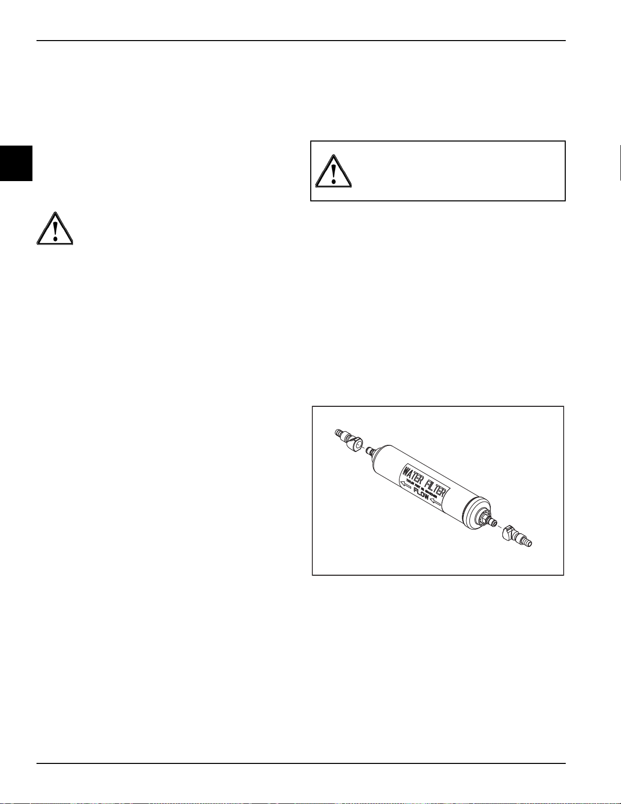
Important! The water filter (064422-SER) must be thor-
oughly flushed with water before connecting it to the
machine. This removes any loose particles present from
the manufacture of the filter that could clog the flow con-
trol. To flush the filter, connect the inlet end of the filter to
the water supply. Position the outlet end of the filter over
an empty pail. Open the water supply. Allow water to flow
through the filter until the water exiting the filter is clear.
Close the water supply. Attach the outlet end of the filter
to the machine. Reopen the water supply.
Figure 1-1
Electrical Connections
Each freezer requires one power supply. Check the data
label on the freezer for fuse, circuit ampacity, and
electrical specifications. See the wiring diagram provided
inside the control box for proper power connections.
In the United States, this equipment is intended to be
installed in accordance with the National Electrical Code
(NEC), ANSI/NFPA 70-1987. In all other areas of the
world, equipment should be installed in accordance with
INSTALL POTABLE WATER CONNECTION
WITH ADEQUATE BACKFLOW
PROTECTION TO COMPLY WITH
APPLICABLE FEDERAL, STATE, AND
LOCAL CODES.

TO THE INSTALLER
1-3
Model C302 NPR
To the Installer
1
the existing local codes. Please contact your local
authorities.

1-4
TO THE INSTALLER
Model C302 NPR To the Installer
1
The purpose of the NEC code is the practical
safeguarding of persons and property from hazards
arising from the use of electricity. This code contains
provisions considered necessary for safety.
Compliance therewith and proper maintenance will result
in an installation essentially free from hazard.The NEC is
a United States regulatory agency. International users
must follow local electrical codes.
WARNING! This machine must be properly
grounded. Failure to do so can result in severe personal
injury from electrical shock.
IMPORTANT! This machine is provided with
an equipotential grounding lug that is to be properly
attached to the rear of the frame by the authorized
installer. The installation location is marked by the
equipotential bonding symbol (5021 of IEC 60417-1) on
the removable panel and the frame.
IMPORTANT!
• Stationary machines which are not equipped
with a power cord and a plug or another device
to disconnect the machine from the power
source must have an all-pole disconnecting
device with a contact gap of at least 0.125 in.
(3 mm) in the external installation.
• Machines that are permanently connected to
fixed wiring and for which leakage currents may
exceed 10 mA, particularly when disconnected
or not used for long periods, or during initial
installation, shall have protective devices to
protect against the leakage of current, such as a
GFI, installed by authorized personnel to local
codes.
• Supply cords used with this machine shall be
oil-resistant, sheathed flexible cable not lighter
than ordinary polychloroprene or other
equivalent synthetic elastomer-sheathed cord
(code designation 60245 IEC 57) installed with
the proper cord anchorage to relieve conductors
from strain, including twisting, at the terminals
and protect the insulation of the conductors from
abrasion.
• If the supply cord is damaged, it must be
replaced by a Taylor service technician to avoid
a hazard.
• Secure supply cord ground lead to machine in a
location where if the cord is pulled the main
power leads become taut before the ground
lead can break loose.
WARNING! This machine must be properly
grounded. Failure to do so can result in severe personal
injury from electrical shock.
Beater Rotation
NOTICE! Beater rotation must be clockwise as
viewed looking into the freezing cylinder.
The following procedures should be performed by a
trained service technician:
To correct rotation on a single-phase unit, change the
leads inside the beater motor. Follow the diagram printed
on the motor.
Note: Three-phase units have single-phase motors.
FOLLOW YOUR LOCAL ELECTRICAL CODES.

TO THE INSTALLER
1-5
Model C302 NPR
To the Installer
1
Refrigerant
CAUTION! This machine contains fluorinated
greenhouse gases (F-Gas) to provide refrigeration using
a hermetically sealed circuit or within foam insulation.
This machine’s type of gas, quantity, Global Warming
Potential (GWP), and CO2tonnes equivalent information
is recorded on the machine’s data label. The refrigerant
used is generally considered nontoxic and
nonflammable. However any gas under pressure is
potentially hazardous and must be handled with caution.
NEVER fill any refrigerant cylinder completely with liquid.
Filling the cylinder approximately 80% will allow for
normal expansion.
CAUTION! Use only approved refrigerant
listed on the machine's data label or authorized through a
manufacturer's technical bulletin. The use of any other
refrigerant may expose users and operators to
unexpected safety hazards.
WARNING! Refrigerant liquid sprayed onto the
skin may cause serious damage to tissue. Keep eyes
and skin protected. If refrigerant burns should occur,
flush the area immediately with cold water. If burns are
severe, apply ice packs and contact a physician
immediately.
NOTICE! Taylor reminds technicians to be
aware of government laws regarding refrigerant recovery,
recycling, and reclaiming systems. If you have any
questions regarding these laws, please contact the
factory service department.
IMPORTANT! Refrigerants and their
associated lubricants may be extremely moisture
absorbent. When opening a refrigeration system, the
maximum time the system is open must not exceed 15
minutes. Cap all open tubing to prevent humid air or
water from being absorbed by the oil.

1-6
TO THE INSTALLER
Model C302 NPR To the Installer
1

Section 2
2-1
Model C302 NPR
To the Operator
2
To the Operator
The freezer you have purchased has been carefully
engineered and manufactured to give you dependable
operation.
The Model C302NP, when properly operated and cared
for, will produce a consistent quality product. Like all
mechanical products, this machine will require cleaning
and scheduled maintenance. A minimum amount of care
and attention is necessary if the operating procedures
outlined in this manual are followed closely.
IMPORTANT! This Operator's Manual should
be read before operating or performing any maintenance
on your machine.
Your Taylor unit will not compensate for and/or correct
any errors made during the setup or filling operations.
Thus, the initial assembly, setup, and priming procedures
are of extreme importance. It is strongly recommended
that all personnel responsible for the unit's operation,
including assembly and disassembly, go through these
procedures together in order to be properly trained and to
make sure that all understand their role in using and
maintaining the unit.
In the event you should require technical assistance,
please contact your local authorized Taylor distributor for
service.
Note: Your Taylor warranty is valid only if the parts are
authorized Taylor parts, purchased from the local
authorized Taylor distributor, and only if all required
service work is provided by an authorized Taylor service
technician. Taylor reserves the right to deny warranty
claims on units or parts if non-Taylor-approved parts or
incorrect refrigerant were installed in the unit, system
modifications were performed beyond factory
recommendations, or it is determined that the failure was
caused by abuse, misuse, neglect, or failure to follow all
operating instructions. For full details of your Taylor
Warranty, please see the Limited Warranty section in this
manual.
Note: Constant research results in steady
improvements; therefore, information in this manual is
subject to change without notice.
IMPORTANT! If the crossed-out waste
container symbol is affixed to this machine, it signifies
that this machine is compliant with the EU Directive as
well as other similar legislation in effect after August 13,
2005. Therefore, it must be collected separately after its
use is completed and cannot be disposed as unsorted
municipal waste. The user is responsible for delivering
the product to the appropriate collection facility as
specified by your local code.
For additional information regarding applicable local
laws, please contact the municipal facility and/or local
distributor.
Compressor Warranty Disclaimer
The refrigeration compressor(s) on this unit are
warranted for the term stated in the Limited Warranty
section in this manual. However, due to the Montreal
Protocol and the U.S. CleanAir Act Amendments of
1990, many new refrigerants are being tested and
developed, thus seeking their way into the service
industry. Some of these new refrigerants are being
advertised as drop-in replacements for numerous
applications. It should be noted that in the event of
ordinary service to this unit's refrigeration system, only
the refrigerant specified on the affixed data label
should be used. The unauthorized use of alternate
refrigerants will void your Taylor compressor warranty. It
is the unit owner's responsibility to make this fact known
to any technician he employs.
It should also be noted that Taylor does not warrant the
refrigerant used in its equipment. For example, if the
refrigerant is lost during the course of ordinary service to
this unit, Taylor has no obligation to either supply or
provide replacement refrigerant either at billable or
unbillable terms. Taylor will recommend a suitable
replacement if the original refrigerant is banned,
obsoleted, or no longer available during the five (5) year
Taylor warranty of the compressor.

2-2
TO THE OPERATOR
Model C302 NPR To the Operator
2
From time to time Taylor may test new refrigerant
alternates. Should a new refrigerant alternate prove
through Taylor's testing that it would be accepted as a
drop-in replacement for this unit, the disclaimer in this
“Compressor Warranty Disclaimer” section will not apply
to the use of the alternate refrigerant approved by Taylor.
To find out the current status of an alternate refrigerant as
it relates to your compressor warranty, call Taylor or your
local authorized Taylor distributor. Be prepared to provide
the model/serial number of the unit in question.
Note: Continuing research results in steady
improvements; therefore, information in this Operator
Manual is subject to change without notice.

Section 3
3-1
Model C302 NPR
Safety
3
Safety
We at Taylor are concerned about the safety of the
operator when he or she comes in contact with the
freezer and its parts. Taylor has gone to extreme efforts
to design and manufacture built-in safety features to
protect both you and the service technician. As an
example, warning labels have been attached to the
freezer to further point out safety precautions to the
operator.
DANGER! Failure to adhere to the following
safety precautions may result in severe personal injury or
death. Failure to comply with these warnings may
damage the machine and its components. Component
damage will result in part replacement expense and
service repair expense.
NOTICE! DO NOT operate the machine
without reading the Operator Manual. Failure to follow
this instruction may result in machine damage, poor
machine performance, health hazards, or personal injury.
IMPORTANT! This machine is to be used only
by trained personnel. It is not intended for use, cleaning,
or maintenance by children or people with reduced
physical, sensory, or mental capabilities or lack of
experience and knowledge, unless given supervision or
instruction concerning the use of the machine by a
person responsible for their safety. Children should be
supervised to ensure that they do not play with the
machine.
WARNING! This machine must NOT be
installed in an area where a water jet or hose can be
used. NEVER use a water jet or hose to rinse or clean
the machine. Failure to follow this instruction may result
in electrocution.
WARNING! Avoid injury.
•DO NOT operate the machine unless it is
properly grounded.
•DO NOT operate the machine with fuses larger
than specified on the machine's data label.
• All repairs should be performed by an
authorized Taylor service technician.
• The main power supplies to the machine must
be disconnected prior to performing installation,
repairs, or maintenance.
•For Cord-Connected Machines: Only Taylor
service technicians or licensed electricians may
install a plug or replacement cord on the
machine.
• Machines that are permanently connected to
fixed wiring and for which leakage currents may
exceed 10 mA, particularly when disconnected
or not used for long periods, or during initial
installation, shall have protective devices to
protect against the leakage of current, such as a
GFI, installed by the authorized personnel to
local codes.
• Stationary machines that are not equipped with
a power cord and a plug or another device to
disconnect the appliance from the power source
must have an all-pole disconnecting device with
a contact gap of at least 0.125 in. (3 mm) in the
external installation.
• Supply cords used with this machine shall be
oil-resistant, sheathed flexible cable not lighter
than ordinary polychloroprene or other
equivalent synthetic elastomer-sheathed cord
(code designation 60245 IEC 57) installed with
the proper cord anchorage to relieve conductors
from strain, including twisting, at the terminals
and protect the insulation of the conductors from
abrasion.
• If the supply cord is damaged, it must be
replaced by the manufacturer, service agent, or
a similarly qualified person to avoid a hazard.
• Secure supply cord ground lead to machine in a
location where if the cord is pulled the main

3-2
SAFETY
Model C302 NPR Safety
3
power leads become taut before the ground
lead can break loose.
Failure to follow these instructions may result in
electrocution. Contact your local authorized Taylor
distributor for service.
WARNING! Avoid injury.
•DO NOT allow untrained personnel to operate
this machine.
•DO NOT put objects or fingers in the door spout.
•DO NOT operate the machine unless all service
panels and access doors are fastened with
screws.
•DO NOT remove the machine door or beater
assembly unless the control switches are in the
OFF position.
WARNING! This machine is pressurized when
in operation. The control switch must be in the OFF
position until the machine is completely assembled. No
part should ever be removed from the machine while it is
in operation. No parts should be removed until the control
switch has been turned to the OFF position.
•
DO NOT
allow untrained personnel to
operate this
machine.
• DO NOT operate the freezer unless all service panels
and access doors are restrained with screws.
• DO NOT remove any internal operating parts
(example: freezer door, beater, scraper blades, etc.)
unless all control switches are in the OFF position.
Failure to follow this instruction may result in severe
personal injury from hazardous moving parts or from the
impact of propelled parts.
WARNING! This machine has many sharp
edges that can cause severe injuries.
•DO NOT put objects or fingers in the door
spout. This may contaminate the product and
cause severe personal injury from blade
contact.
•USE EXTREME CAUTION when removing the
beater assembly. The scraper blades are very
sharp.
Failure to follow these instructions can result in personal
injury or damage to the machine.
CAUTION! This machine must be placed on a
level surface. Failure to comply may result in personal
injury or machine damage.
WARNING! Only install this machine in a
location where its use and maintenance is restricted to
trained personnel. Failure to comply may result in
personal injury.
NOTICE! Cleaning and sanitizing schedules
are governed by your federal, state, or local regulatory
agencies and must be followed accordingly. Please refer
to the cleaning section of this manual for the proper
procedure to clean this machine.
WARNING! Asphyxiation Hazard!
If used with CO2(Carbon Dioxide) or N2(Nitrogen),
always make sure the area is well ventilated.
Vent exhaust gas to outside atmosphere using a hose.
Failure to do so can cause serious injury.
CAUTION! This machine is designed to
maintain product temperature under 41°F (5C). Any
product being added to this machine must be below 41F
(5C). Failure to follow this instruction may result in
health hazards and poor machine performance.
Do not run the unit without product. Failure to follow this

SAFETY
3-3
Model C302 NPR
Safety
3
instruction can result in damage to the unit.
Do not obstruct air intake and discharge openings: Air-
cooled units require a minimum of 3 in. (76 mm) of air
space on both sides, 3 in. (76 mm) at the rear and
12 in. (305 mm) on the top of the unit. Minimum air
clearances must be met to ensure adequate air flow for
optimum performance.
For Indoor Use Only: This unit is designed to operate
indoors, under normal ambient temperatures of
70°F to 75°F (21°C to 24°C). The freezer has
successfully performed in high ambient temperatures of
104°F (40°C) at reduced capacities.
NOISE LEVEL: Airborne noise emission does not
exceed 78 dB(A) when measured at a distance of 1.0
meter from the surface of the machine and at a height of
1.6 meters from the floor.

3-4
SAFETY
Model C302 NPR Safety
3
Notes:

Section 4
4-1
Model C302 NPR
Operator Parts Identification
4
Operator Parts Identification
C302NP
Figure 4-1
12
4
3
5
6
7
8
9
10
11
30005_A
Item Description Part No.
1 Panel-Side Left 059721
2 Panel-Rear 059657
3 Panel-Side Right 059722
4 Display-LED 15.4"Tall 068575
5 Panel-Front-Upper 068909
6 Panel-Front-Shell 059576
Item Description Part No.
7 ANEL-Front-Lower 059652
8 Shelf-Drip Tray 059653
9 Tray-Drip 059654
10 Shield-Splash 059659
11 Switch-Rocker SPST OFF-ON 059627

4-2
OPERATOR PARTS IDENTIFICATION
Model C302 NPR Operator Parts Identification
4
Beater Door Assembly
Figure 4-2
1c
1b
1e
8
7
6
11
1f
1h
35
4
5
10
2
1g
1d
1i
1a
9
Item Description Part No.
1 Door A.-Slush-SLFCLOSE-
Ice Buster 1a-1i
1a Buster-Ice 047735
1b Spring-Comp 030344
1c Pin A.-Valve Handle X83812
1d Valve-Draw Self Close 080662
1e O-ring-1"OD X .139W 032504
1f Handle a.-Draw-Slushblack X47384
1g Plug-Prime*STNLS 050405
1h O-ring-.563 OD X .070W-#013 043758
*1i Door A.-Slush-Partial Selfclose X83427SSP
Item Description Part No.
2 Gasket-Door 5.109ID X 5.63 014030
3 Bearing-Front 013116
4 Beater A.-7QT-1 Pin X46233
5 Blade-Scraper 084950
6 Shaft-Beater 036412
7 O-ring-7/8 OD X .139W 025307
8 Seal-Drive Shaft 032560
9 Arm-Baffle 047729
10 Baffle A. X47731
11 Nut-Stud 043666

OPERATOR PARTS IDENTIFICATION
4-3
Model C302 NPR
Operator Parts Identification
4
Accessories
Figure 4-3
Items 2a-2d are included in Brush A.-Package X64275.
*Note: A sample container of sanitizer is sent with the
unit. For reorders, order Stera Sheen part no. 055492
(100 2 oz. packs) or Kay-5 part no. 041082 (200 packs).
Apply the appropriate
Taylor approved food safe lubricant.
HP
3
2d
2c
2a
5
4
1
2b
Item Description Part No.
1 Pail-10 qt 013163
2 Brush A.-Package X64275
2a Brush-Mix Pump Body-3”X7” 023316
2b Brush-Double Ended 013072
2c Brush-Rear BRG 1”DX2“L 013071
Item Description Part No.
2d Brush-Draw Valve 1-1/2”OD 014753
3 Kit A.-Tune Up X56829
4 Lubricant-Taylor Hi PERF 048232
*5 Sanitizer Stera Sheen See Note

4-4
OPERATOR PARTS IDENTIFICATION
Model C302 NPR Operator Parts Identification
4
Notes:
Table of contents
Other Taylor Beverage Dispenser manuals
Popular Beverage Dispenser manuals by other brands

Salton
Salton CU-60 manual

Cornelius
Cornelius IDC 2 Series Service manual

Follett
Follett VU300LH Installation, operation and service manual

Curtis
Curtis PCGT4 Service manual

Schroeder America
Schroeder America 959 Installation instruction, parts list and configuration guide

Crathco
Crathco PIC 4 Service manual

New Air
New Air Thermoelectric Wine Cooler AW-280E instruction manual

Servend
Servend STH14 Technician's handbook

Marvel
Marvel 61WCM Installation, operating and maintenance instructions

Silver King
Silver King SKBD110P Technical manual and replacement parts list

Continental Refrigerator
Continental Refrigerator KC50-CT Specification sheet

Cornelius
Cornelius IDC215 Specifications