Sure Vend 673 User manual


This machine has been engineered to our own rigid safety and performance standards. It
has been designed to comply with sanitation and health guidelines recommended by the
Automatic Merchandising Health-Industry Council (AMHIC) and it conforms with all
other NAMA safety recommendations.
This machine has been manufactured in accordance with the safety standards of both
Underwriter’s Laboratories and the Canadian Standards Association. To maintain this
degree of safety and to continue to achieve the level of performance built into this
machine, it is important that installation and maintenance be performed so as to not alter
the original construction or wiring and that replacement parts are as specified in the Parts
Manual. Your investment in this equipment will be protected by using this Setup and
Operator’s Guide, the Programming Guide, and the Parts Manual in your operation, ser-
vice and maintenance work. By following prescribed procedures, machine performance
and safety will be preserved.
Crane Merchandising Systems Parts and Support
Phone Numbers:
Parts: 1-800-621-7278
Service: 1-800-628-8363

Hot Drink Center II Set-Up Manual
6730013 i
February, 2003
Table of Contents
Title Page
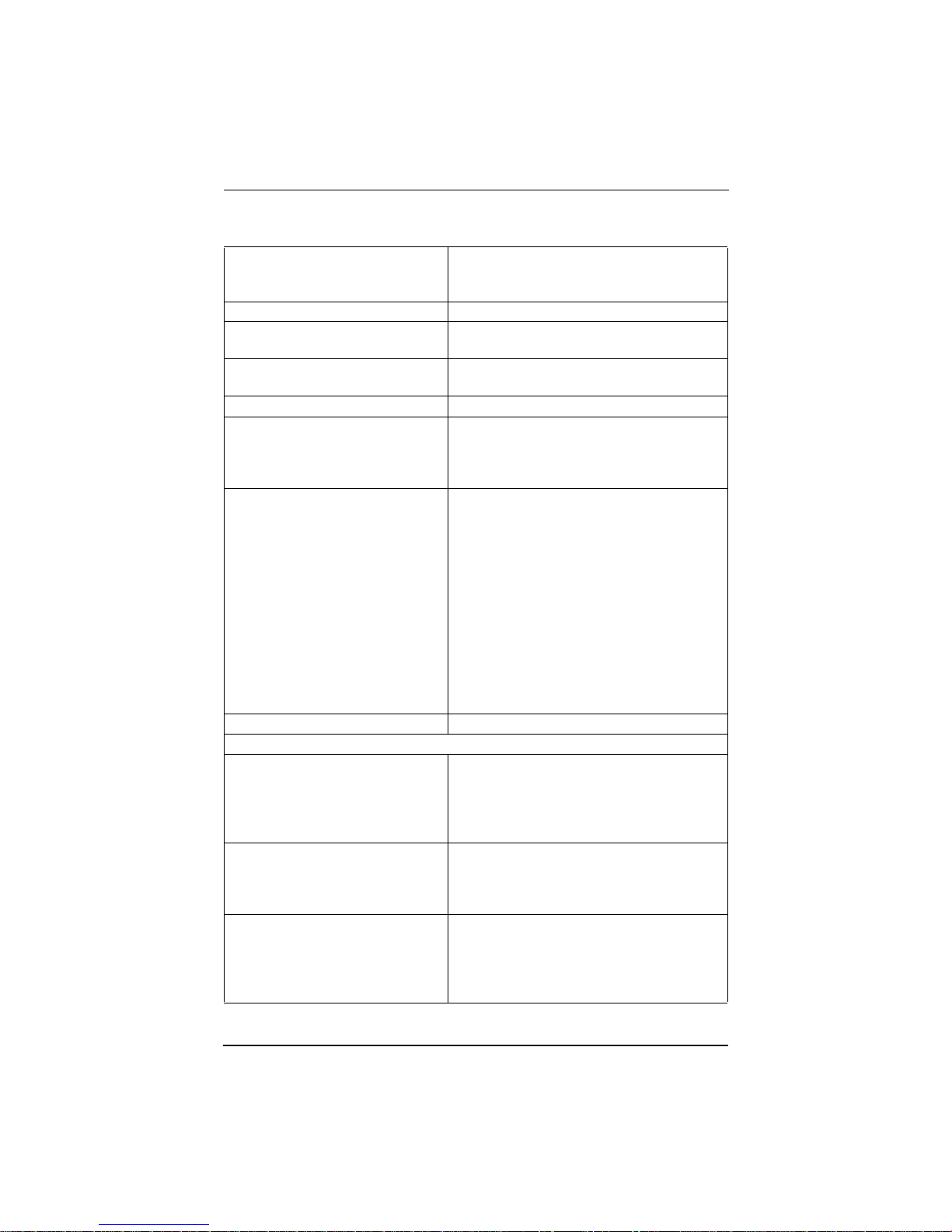
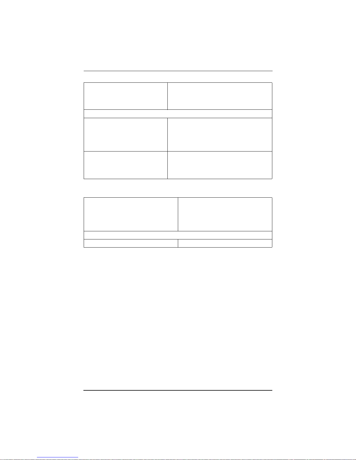
SPECIFICATIONS............................................................................................ 1
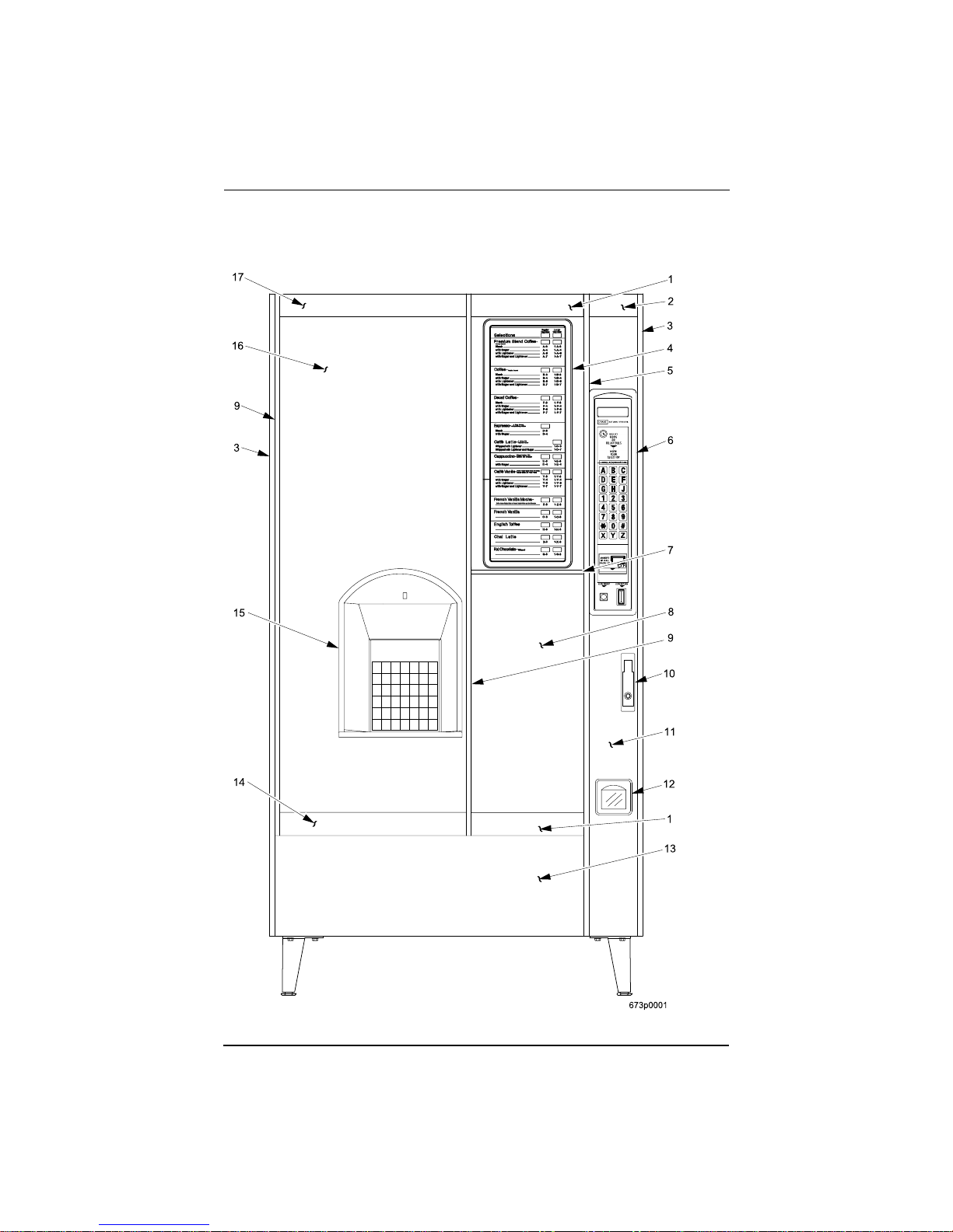
MAJOR PARTS ................................................................................................. 4
CONTROLS AND INDICATORS ................................................................... 8
INITIAL SET-UP ............................................................................................. 14
Location Preparation ................................................................................... 14
Water Requirements ................................................................................ 15
Positioning the Merchandiser...................................................................... 16
Connecting Everything................................................................................ 16
Connect the Merchandiser to the Water Supply: ................................. 16
Connect the Merchandiser to the Electrical Power Supply: ................ 16
Final Mechanical Preparation...................................................................... 16
Level the Merchandiser:....................................................................... 16
Mount the Base Plate: .......................................................................... 17
Set Up the Menu Assembly ................................................................. 18
Install the Water Filter Cartridge: ........................................................ 19
Load the Optional Filter Paper:............................................................ 22
Install the Optional Coin Box Lock ..................................................... 24
Load the Coin Mechanism ................................................................... 24
Fill the Tank:........................................................................................ 24
Fill the Canisters: ................................................................................. 25
Load Cups: ........................................................................................... 26
Tell the Machine About the Cup Size(s):............................................. 27
Test the Machine:................................................................................. 28
ADJUSTMENTS AND MINOR MAINTENANCE...................................... 29
Water Valve Adjustment............................................................................. 29
Cup Mechanism Adjustment....................................................................... 30
Grinder Adjustment..................................................................................... 31
Disengaging the Grinder ............................................................................. 32
Canister Installation..................................................................................... 32
Removing POP to Service fluorescent lights, Starters and ballasts............ 33
SANITATION................................................................................................... 34
Basics .......................................................................................................... 34
Clean the Hot Water Tank........................................................................... 36
Sanitation Procedures.................................................................................. 36
Food-Contact Parts .................................................................................. 36
Non Food-Contact Parts .......................................................................... 37
Brewer Cleaning.......................................................................................... 38
Overall Cleaning ......................................................................................... 44
Preventive Maintenance Cleaning............................................................... 44

Hot Drink Center II Set-Up Manual
ii 6730013
February, 2003
Notes . . .
________________________________________________________________
________________________________________________________________
________________________________________________________________
________________________________________________________________
________________________________________________________________
________________________________________________________________
________________________________________________________________
________________________________________________________________
________________________________________________________________
________________________________________________________________
________________________________________________________________
________________________________________________________________
________________________________________________________________
________________________________________________________________
________________________________________________________________
________________________________________________________________
________________________________________________________________
________________________________________________________________
________________________________________________________________
________________________________________________________________
________________________________________________________________
________________________________________________________________

Hot Drink Center II Set-Up Manual
6730013 1
February, 2003
SPECIFICATIONS
SPECIFICATIONS COMMON TO ALL MACHINES
DIMENSIONS 72" (183 cm) high
38.12" (97 cm) wide
28.5" (72 cm) deep
WEIGHT 570 lbs (258.5 kg)
WATER REQUIREMENTS Minimum: 20 psi (137.8 kPa)
Maximum: 80 psi (551.2 kPa)
AMBIENT TEMPERATURE Minimum: 41× F (5× C)
Maximum: 90× F (32× C)
OPERATING ENVIRONMENT For indoor use only
CUP CAPACITIES
(APPROXIMATE) 12 oz cups = 600
14 oz cups = 530
16 oz cups = 380
20 oz cups = 358
CANISTER CAPACITIES
(APPROXIMATE) Regular coffee beans - 14 lbs
Ground coffee - 13 lbs
Freeze dry coffee - 2 lbs
Decaf coffee beans - 9.5 lbs
Ground decaf coffee - 9 lbs
Freeze dry decaf - 2 lbs
Chocolate - 10 lbs
Soup - 6.7 lbs
Sugar - 11 lbs
Lightener - 4.5 lbs
Sugar substitute - 4 lbs
Tea (freeze dry) - 1.5 lbs
6th and 7th products (freeze dry) - 6 lbs each
FILTER PAPER CAPACITY 2400 vends per roll
PRODUCT OPTIONS
MODEL 673 FRESH BREW Up to eleven selections of fresh brew regular and
decaf coffee, freeze dried regular and decaf cof-
fee, fresh brew and freeze dried tea, soup, choco-
late, cappuccino, espresso, caffè latte, and two
blended drinks.
MODEL 675 FREEZE DRIED Up to eleven selections of freeze dried regular
coffee, decaf coffee, tea, soup, chocolate, cap-
puccino, espresso, caffè latte, and two blended
drinks.
MODEL 677 FRESH BREW
WITH
BEAN GRINDER
Up to nine selections of fresh ground and brewed
regular and decaf coffee, freeze dried regular and
decaf coffee, fresh brew and freeze dried tea,
soup, chocolate, cappuccino, espresso, caffè
latte, and two blended drinks.

Hot Drink Center II Set-Up Manual
26730013
February, 2003
OPTIONS AND ACCESSORIES
OPTIONS Coin box lock
Base grille kit
Automatic delivery door
Flex Ace door lock and key
Van Door lock and key
Sugar substitute kit
6th product kit
Cup/mug electronic sensor (cup hold switch kit)
Snap-on ingredient canister
extension sleeves (4 tall)
Everpure water filter system
CUNO water filter system
Debit card validator
Free vend keyswitch
Data printer kit
Ingredient rinse tray
SPECIFICATIONS COMMON TO ALL MACHINES (Continued)

Hot Drink Center II Set-Up Manual
6730013 3
February, 2003
SPECIFICATIONS UNIQUE TO 115 VOLT MACHINES
ELECTRICAL 115 Volts AC
60 Hertz
16 Amps
Single phase
OPTIONS AND ACCESSORIES
COIN MECHANISM MARS TRC-6000
COINTRON 3000
MARS TRC-6010XV (24 V)
Maka/Conlux Model USPX-004 (24 V)
Coin Acceptors Model 9302-LF (24 V)
BILL VALIDATORS MARS VFM1 pulse
MARS VFM3 serial
MAKA pulse
COINCO
SPECIFICATIONS UNIQUE TO 220 - 240 VOLT MACHINES
ELECTRICAL 220-240 Volts AC
50 Hertz
10 Amps
2 kW
Single phase
OPTIONS AND ACCESSORIES
COIN MECHANISM Executive coin mechanism interface

Hot Drink Center II Set-Up Manual
46730013
February, 2003
MAJOR PARTS
The diagrams on the following pages will acquaint you with the major parts of the Hot
Drink Center. For more detailed information, please consult your PARTS MANUAL. If
you do not have a PARTS MANUAL, contact National Vendors Parts Department.
Door Assembly - Exterior

Hot Drink Center II Set-Up Manual
6730013 5
February, 2003
Door Assembly - Interior

Hot Drink Center II Set-Up Manual
66730013
February, 2003
Cabinet Assembly Interior - Part 1

Hot Drink Center II Set-Up Manual
6730013 7
February, 2003
Cabinet Assembly Interior - Part 2

Hot Drink Center II Set-Up Manual
86730013
February, 2003
CONTROLS AND INDICATORS
POWER PANEL. You may have one of three power panels, depending upon
where you live. The controls are fundamentally the same, however.
Circuit Breakers and Fuses. Circuit breakers and fuses protect the merchan-
diser against failures in the power supply or any of the electrical components. If
a circuit breaker trips and cannot be reset, or if a fuse repeatedly blows, contact a
field service representative.
Back Side of U.S./ Canada Power Control Panel. The circuit board mounted
on therear of the U.S. and Canadian power control panel is a dc power supply for
the coin mechanism. A fuse protects the board circuitry in the event of a coin
mechanism solenoid failure. If the coin mechanism is not working, check this
fuse. If the fuse is blown, a bad coin mechanism solenoid could be at fault.
Main Power Switch. This is the main ON/OFF switch for the merchandiser.
WARNING
To protect against electrical shocks and possible damage to the
machine, turn this switch OFF when performing any mainte-
nance on the merchandiser.
Power Control Panel (France/Germany/Spain)
LABEL
MAIN
POWER
SWITCH
ELECTRONICS
BREAKER
O
I
626P0005

Hot Drink Center II Set-Up Manual
6730013 9
February, 2003
Power Control Panel (U.S./Canada)
Back Side of U.S./Canada Power Panel
LABEL MAIN
CIRCUIT
BREAKER
MAIN
POWER
SWITCH
LOW VOLTAGE
CIRCUIT BREAKER
OFF
ON
626P0006

Hot Drink Center II Set-Up Manual
10 6730013
February, 2003
Power Control Panel (U.K./Mexico)
LABEL
MAIN POWER
SWITCH
ELECTRONICS
CIRCUIT BREAKER
MOUNTING STUDS
FOR MEXICO ONLY
OFF
ON
626P0035a

Hot Drink Center II Set-Up Manual
6730013 11
February, 2003
Main Controller PCB Display
Main Controller PCB Display.This display consists of two light emitting diodes (LED)
mounted on the controller PCB.
POWER ON
(LED 1) When lit, this red LED indicates electrical power is applied to the controller
PCB.
HEARTBEAT
(LED 2) When flashing, this red LED indicates that the controller PCB is active, and
the software is operating.
LED1 LED2
MAIN CONTROLLER
PCB ASSEMBLY
POWER ON
(LED 1) FLASHING
HEARTBEA
T
(LED 2)
NORMAL CONDITIONS:
When the merchandiser is operating normally, you should see a
steady red POWER ON indicator. The red HEARTBEAT indi-
cator should be flashing with a balanced on/off pattern (on for
the same length of time that it is off).
ERROR CONDITIONS:
If an error is present, the red HEARTBEAT indicator will flash
with an unbalanced on/off pattern (on longer than it is off). The
error(s) can be viewed under the DIAGNOSTICS mode.

Hot Drink Center II Set-Up Manual
12 6730013
February, 2003
Monetary Panel

Hot Drink Center II Set-Up Manual
6730013 13
February, 2003
High Voltage Interlock Switch (U.S./Canada). When the cabinet door is open,
this switch turns off the optional fan and bean light (if so equipped) and turns on
the service light.
HighVoltageInterlock Switch (International). When the cabinet door is open,
this switch turns off all high voltage to the cabinet. Pulling the switch out
restores high voltage for maintenance purposes.
Low Voltage Door Switch. Informs the controller software of the main door
open or closed status.
Message Display. This is how the merchandiser communicates with the outside
world. Customers can see messages about how much money they have put into
the merchandiser. The message display also tells customers when a selection is
sold out and when vending is free, inhibited, or discounted. The message display
shows you what you are doing when you program the merchandiser, and can
show you what is wrong if there is a failure.
Free Vend Keyswitch. This allows someone (other than maintenance people) to
set the merchandiser to free vend without opening the door.
Selection Switch Panel. The customer uses these switches to make selections.
Also, maintenance people may use this switch panel during programming and
other support modes.
Coin Return Button. Pressing this button returns any coins that have been paid
into the merchandiser prior to a vend.
Bill Acceptor (Optional). Accepts bills in various denominations, depending
upon the type of bill validator, and how the machine is configured.
Service Keypad. The service keypad is located at the top of the monetarypanel.
It gives service personnel the means to program, retrieve data from, and view
diagnostic information about, the merchandiser.
Service Keypad

Hot Drink Center II Set-Up Manual
14 6730013
February, 2003
INITIAL SET-UP
I. Location Preparation
After your machine is unpacked and placed near its permanentlocation, you need
to make sure you have the proper electrical and water service.
This merchandiser needs electrical power as shown in the following table.
NOTE: Each merchandiser should have its own electrical circuit.
This merchandiser is supplied with a service cord for the country of use and is
terminated in a grounding type plug. The wall receptacle used for this merchan-
diser must be properly polarized, grounded, and of the correct voltage. Operating
the merchandiser from a source of low voltage will VOID YOUR WARRANTY.
Each merchandiser should have its own electrical circuit and that circuit should
be protected with a circuit breaker or fuse conforming to local regulations.
Voltage Check - Place the leads of a voltmeter across the LINE (LIVE) and
NEUTRAL terminals of the wall receptacle. The voltmeter should indicate
110-130 volts ac for 120 volt, 60 Hz locations, or 220-240 volts ac for 230
volt, 50 Hz locations.
Polarity Check - Place the leads of a voltmeter across the LINE (LIVE) and
GROUND terminals of the wall receptacle. The voltmeter should indicate
110-130 volts ac for 120 volt, 60 Hz locations, or 220-240 volts ac for 230
volt, 50 Hz locations.
Noise Potential Check - Place the leads of a voltmeter across the NEU-
TRAL and GROUND terminals of the wall receptacle. The voltmeter
should indicate 0 volts ac. A measurement greater than 1.5-2.0 volts ac
could result in problems for the merchandiser's electronic circuitry caused by
electrical noise.
Any deviation from these requirements could result in unreliable performance
from your merchandiser.
Power Requirements
Country Volts Frequency (Hz) Current (Amps)
Canada 115 60 16
France 230 50 10
Germany 230 50 10
United Kingdom 230 50 10
United States 115 60 16

Hot Drink Center II Set-Up Manual
6730013 15
February, 2003
Water Requirements
The best type of water for coffee brewing is normal hard (tap) water. If your
location has chemically softened water, you should do one of the following
things:
• Have a non-softened supply line run to the merchandiser
• Contact your local water filter supplier for information and suggestions
Wellwater can also be used in the Hot Drink Center. However,
you should have it checked for levels of carbonates and alka-
lies. Contact your water filter supplier if these values are rela-
tively high.
What is the Water Pressure at Your Location?
It should be no less than: 10 psi ( 69.0 KPa) at 1/2 gallon/minute
Andnomorethan: 80 psi (522.0 KPa) at 1/2 gallon/minute
If you're not sure about the pressure and flow rate, check with your water com-
pany.
What to do With the Water Supply Line:
• Locate the supply line at the rear of your merchandiser.
• Equip the line with a shut-off valve.
Flush the water supply line before connecting it to the merchandiser. A mini-
mum of five gallons is usually required before connecting the merchandiser to
the supply line. DO NOT flush the merchandiser water system. If you do, you
might introduce water line contaminants into the merchandiser.
This manual suits for next models
3
Table of contents
Popular Beverage Dispenser manuals by other brands

Skyflo
Skyflo Wireless Liquor Management System user guide

Curtis
Curtis PCGT3 troubleshooting guide

Newco
Newco LCD-2 Installation and programming guide

Manitowoc
Manitowoc LP-3 5027727 Installation & service guide

Grindmaster
Grindmaster PIC-5 Five Flavor Specifications

Kenmore
Kenmore 564.8815022 Owner's instructions

Cornelius
Cornelius Visual Display Dispenser JS7-W25 owner's manual

SaniServ
SaniServ WB Series Operation manual

Bunn
Bunn FMD-4 OPERATING & SERVICE MANUAL

Cornelius
Cornelius FlavorFusion 255 installation instructions

Cornelius
Cornelius FCB - 2 Flavor Service manual

Cecilware
Cecilware GB1HC-CP Brochure & specs