2
taylormadeproducts.com/wavemaker 574-537-8900 Rev:06.05.20
Taylor Made®
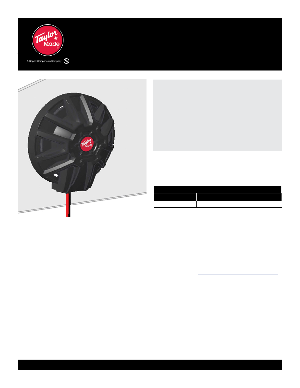
Exciter Speaker
Installation and Owner’s Manual
(For Aftermarket Applications)
CCD-0003868
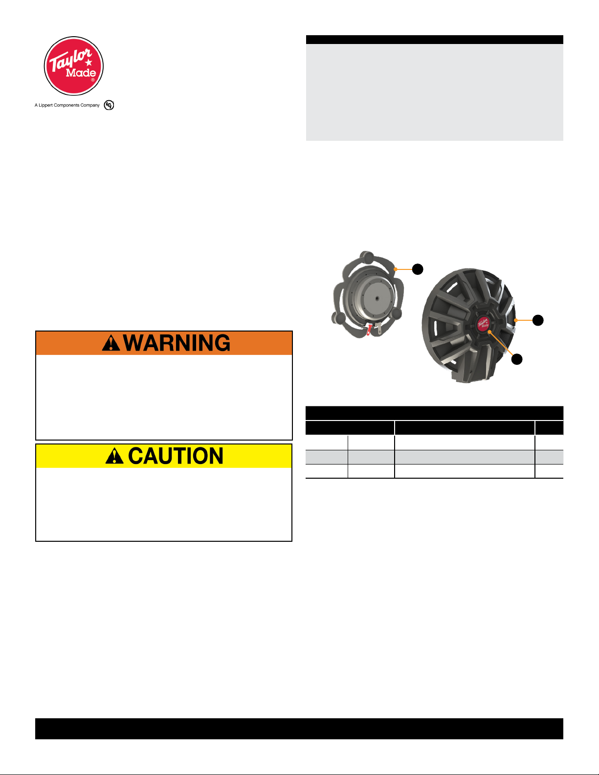
Taylor Made Exciter Speaker Kit - 2020102048Taylor Made Exciter Speaker Kit - 2020102048
LetterLetter PNPN DescriptionDescription QtyQty
A811750 Exciter, Marine 50W 2
B 811751 Exciter Plastic Cover, 2.5” 2
C N/A Taylor Made Ball Logo 2
Safety
Read and fully understand all instructions before installing
or operating this product. Adhere to all safety labels.
This manual provides general instructions. Many variables
can change the circumstances of the instructions, i.e., the
degree of difficulty, operation and ability of the individual
performing the instructions. This manual cannot begin to
plot out instructions for every possibility, but provides the
general instructions, as necessary, for effectively interfacing
with the device, product or system. Failure to correctly
follow the provided instructions may result in death, serious
personal injury, severe product and/or property damage,
including voiding of the LCI limited warranty.
Parts List
NOTE: Part numbers are shown for identification purposes
only. Not all parts are available for individual sale. All parts
with a link to the taylormadeproducts.com/wavemaker can
be purchased.
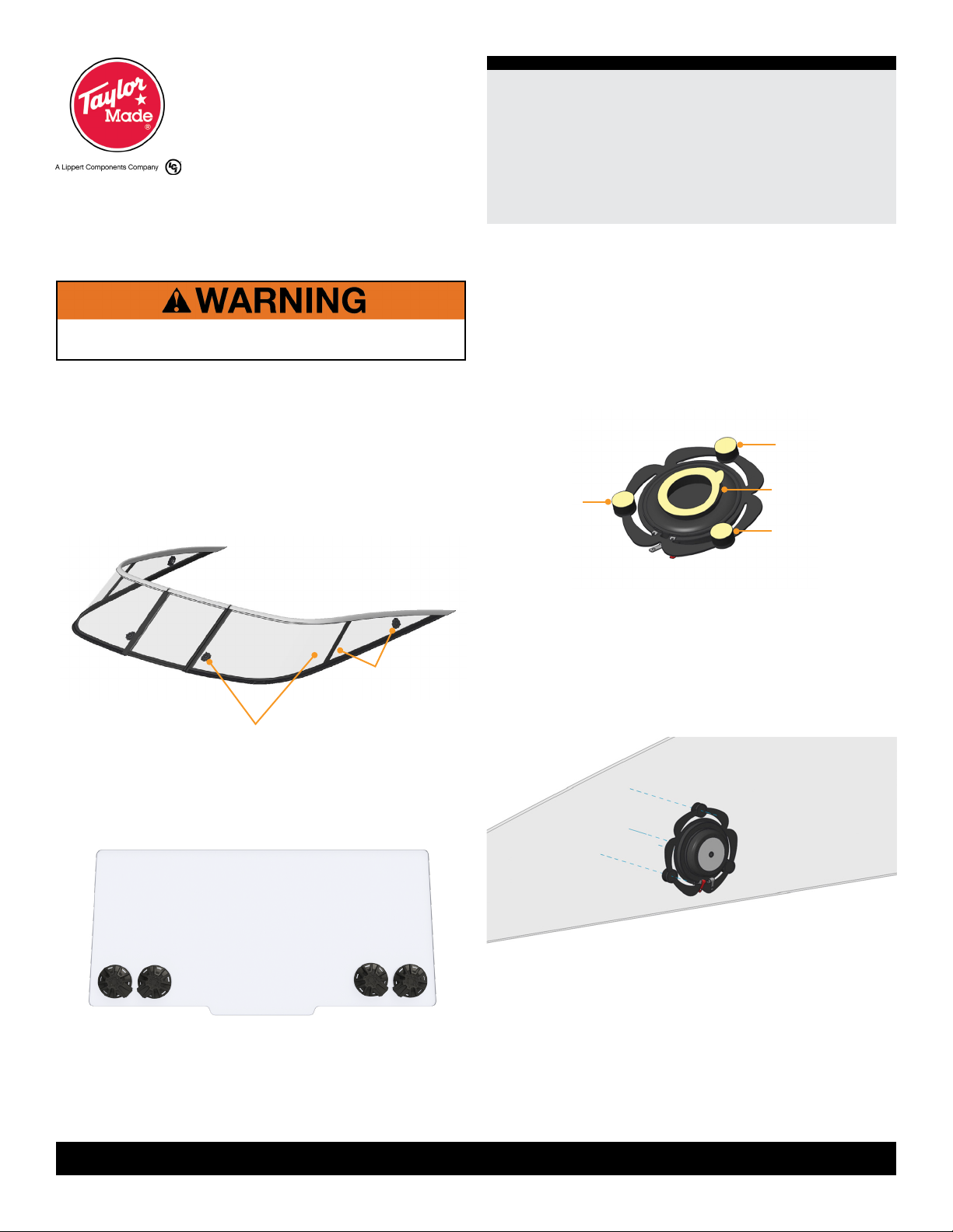
Resources Required
• Rubbing alcohol
• Clean, lint-free cloth
THE “WARNING” SYMBOL ABOVE IS A SIGN THAT
AN INSTALLATION PROCEDURE HAS A SAFETY
RISK INVOLVED AND MAY CAUSE DEATH OR
SERIOUS PERSONAL INJURY, SEVERE PRODUCT
OR PROPERTY DAMAGE IF NOT PERFORMED
SAFELY AND WITHIN THE PARAMETERS SET FORTH
IN THIS MANUAL.
THE “CAUTION” SYMBOL ABOVE IS A SIGN THAT
AN INSTALLATION PROCEDURE HAS A SAFETY
RISK INVOLVED AND MAY CAUSE PERSONAL
INJURY OR PRODUCT DAMAGE IF NOT PERFORMED
SAFELY AND WITHIN THE PARAMETERS SET FORTH
IN THIS MANUAL.
A
B
C