TAYO Zontes ZT125-M 2022 User manual

1 / 188
ZT125/310T-M
Maintenance Manual
2022-09-14

2 / 188
Introduction
All the materials, illustrations, photos, etc. collected in this manual are compiled according to the latest products of ZT310-
M National IV. However, due to the continuous improvement of the product and other changes, there may be some
inconsistencies between your motorcycle and this manual. For colors or upgrades, please refer to the part codes on the official
website of Zontes. This manual will not be listed in detail; if the part names in this manual are inconsistent with the official
website of Zontes, please refer to the official website of Zontes.Individual parts of different displacements that differ in shape or
size but are disassembled and assembled in the same way, will not listed in this manual.
The M125 steps are similar to the M310, taking the M310 as an example.
If part of the content of this manual is insufficient, please refer to the "Driver's Manual" included with the bike. The latest
version of the driver's manual can be downloaded as a PDF in the model introduction corresponding to the official website of
Zontes.
©GUANG DONG TAYO MOTORCYCLE TECHNOLOGY Co.,Ltd
All rights reserved

3 / 188
User notice
This manual is compiled by Guangdong Tayo Motorcycle Technology Co., Ltd. to guide dealers or service personnel to use it. This
manual cannot provide more detailed knowledge about motorcycles, and is only for reference for maintenance. If you do not
have the corresponding knowledge such as electrician, machine repair, etc., improper assembly or repair failure may occur
during repair.
If you need to clean or wash the body parts of the vehicle, you should use neutral car wash fluid or tap water, diesel, kerosene,
etc. Acidic or alkaline car wash liquid will cause irreversible corrosion of the surface paint, electroplating surface, and anodized
surface of the parts; gasoline will cause premature aging or hardening of sealants, gaskets, and rubber parts, reducing the
service life. Non-woven fabrics should be used for wiping with no residue. Ordinary rags may leave cloth scraps or wool, etc.,
which may affect the assembly or cause other adverse effects.
Our company will update this manual as soon as possible after the product changes.
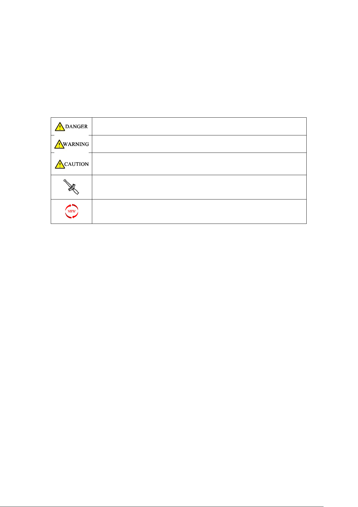
The following is the meaning of the icons marked in this manual:
Failure to observe will cause personal injury or death of the driver or maintenance
personnel; or cause serious damage to parts and shorten the service life, etc.
Failure to comply may result in personal injury or death of the driver or maintenance
personnel; or damage to parts, abnormalities, etc.
Failure to observe the warning will cause personal injury to the driver or
maintenance personnel; or matters requiring special attention during disassembly
and assembly
Indicates that there is a requirement for torque there
Indicates that the piece needs to be replaced after disassembly

4 / 188
Content
Content ............................................................................................................................................................................................... 4
1. Vehicle information ...................................................................................................................................................................... 12
Know Before Service ......................................................................................................................................................... 12
Body label ................................................................................................................................................................................. 13
M310 Technical specification.................................................................................................................................................... 14
Front wheel/steering system ............................................................................................................................................ 14
Rear wheel/suspension system ........................................................................................................................................ 14
Brake system..................................................................................................................................................................... 14
Battery/charging system ................................................................................................................................................... 15
M125 Technical specification.................................................................................................................................................... 15
Front wheel/steering system ............................................................................................................................................ 15
Rear wheel/suspension system ........................................................................................................................................ 16
Brake system..................................................................................................................................................................... 16
Battery/charging system ................................................................................................................................................... 16
Lamp/Speedometer/switch description ................................................................................................................................... 17
Tightening torque ..................................................................................................................................................................... 17
Bolt tightening torque of general tightening part............................................................................................................. 17
Cable/cable/pipe/electrical device distribution map ............................................................................................................... 18
1. Distribution map of lamps and lanterns ....................................................................................................................... 18
2. Throttle cable ................................................................................................................................................................ 18
3. Brake upper pump and brake hose............................................................................................................................... 19
4. Calipers, brake hoses and wheel speed sensors ........................................................................................................... 19
5. Distribution map of brake system accessories.............................................................................................................. 20
5.1 M310 ................................................................................................................................................................... 20
5.2 M125 ................................................................................................................................................................... 21
6. Oil supply system .......................................................................................................................................................... 22
6.1 M310 Fuel evaporation ....................................................................................................................................... 22
6.2 M125 Fuel evaporation....................................................................................................................................... 23
6.3 M310 Fuel supply ................................................................................................................................................ 23
6.4 M125 Fuel supply ................................................................................................................................................ 24
7. Distribution map of cooling system accessories ........................................................................................................... 24
7.1 M310 ................................................................................................................................................................... 24
7.2 M125 ................................................................................................................................................................... 25
8. Electrical device layout.................................................................................................................................................. 26
9. Intake and exhaust system............................................................................................................................................ 28
9.1 M310 ................................................................................................................................................................... 28
9.2 M125 ................................................................................................................................................................... 29
Tool ........................................................................................................................................................................................... 30
Swell nail description ................................................................................................................................................................ 32
2. Maintenance ................................................................................................................................................................................. 33
Know Before Service ................................................................................................................................................................. 33
M310 Maintenance schedule ................................................................................................................................................... 34
M125 Maintenance schedule ................................................................................................................................................... 35
M310 Air filter (filter element), air inlet filter element ............................................................................................................ 36
1. Support the vehicle firmly............................................................................................................................................. 36
2. Remove the left engine cover ....................................................................................................................................... 36
3. Remove the air inlet cover ............................................................................................................................................ 36
4. Replace the air inlet filter.............................................................................................................................................. 37
5. Remove the air filter housing........................................................................................................................................ 37
6. Replace Air filter element ............................................................................................................................................. 37
7. Inspection air filter waste oil pipe................................................................................................................................. 37
8. Reinstall......................................................................................................................................................................... 38
M125 Air filter (filter element), air inlet filter element ............................................................................................................ 39
1. Support the vehicle firmly............................................................................................................................................. 39
2. Remove the left engine cover ....................................................................................................................................... 39
3. Replace the air inlet filter.............................................................................................................................................. 39
4. Remove the air filter housing........................................................................................................................................ 40
5. Replace Air filter element ............................................................................................................................................. 40

5 / 188
6. Inspection air filter waste oil pipe................................................................................................................................. 40
7. Reinstall......................................................................................................................................................................... 40
Bolts and nuts of muffler .......................................................................................................................................................... 41
1. Check for air leaks at the engine exhaust. .................................................................................................................... 41
2. Check for nut and bolts at the muffler.......................................................................................................................... 41
M310 Spark plug ....................................................................................................................................................................... 42
1. Disassemble the spark plug........................................................................................................................................... 42
2. Check the spark plug ..................................................................................................................................................... 43
3. Refer to the steps to remove the spark plug to restore all parts.................................................................................. 43
M125 Spark plug ....................................................................................................................................................................... 44
1. Disassemble the spark plug........................................................................................................................................... 44
2. Check the spark plug ..................................................................................................................................................... 45
3. Refer to the steps to remove the spark plug to restore all parts.................................................................................. 45
Engine oil................................................................................................................................................................................... 45
M310 ................................................................................................................................................................................. 46
1. Drain the oil........................................................................................................................................................... 46
2. Replace fine filter .................................................................................................................................................. 46
3. Add oil ................................................................................................................................................................... 46
4. Change gear box oil............................................................................................................................................... 47
5. Confirm the oil level .............................................................................................................................................. 47
M125 ................................................................................................................................................................................. 47
1. Drain the oil........................................................................................................................................................... 47
2. Replace fine filter .................................................................................................................................................. 48
3. Add oil ................................................................................................................................................................... 48
4. Change gear box oil............................................................................................................................................... 49
5. Confirm the oil level .............................................................................................................................................. 49
M310 Throttle valve body......................................................................................................................................................... 49
1. Do not dismantle the throttle body to clean up carbon deposits................................................................................. 49
2. Remove the stepper motor and clean up carbon deposits........................................................................................... 49
3. Remove the throttle valve body assembly to clean up carbon deposits ...................................................................... 51
4. Disassemble the three-in-one sensor ........................................................................................................................... 52
5. Throttle valve body troubleshooting process ............................................................................................................... 53
M125 Throttle valve body......................................................................................................................................................... 53
1. Do not dismantle the throttle body to clean up carbon deposits................................................................................. 53
2. Remove the stepper motor and clean up carbon deposits........................................................................................... 53
3. Remove the throttle valve body assembly to clean up carbon deposits ...................................................................... 54
4. Disassemble the sensor................................................................................................................................................. 55
5. Throttle valve body troubleshooting process ............................................................................................................... 55
Throttle cable............................................................................................................................................................................ 56
1. Inspection...................................................................................................................................................................... 56
2. Adjust the throttle cable clearance............................................................................................................................... 56
3. Lube door cable............................................................................................................................................................. 56
Idle speed.................................................................................................................................................................................. 57
Check idle speed: .............................................................................................................................................................. 57
Fuel evaporative pollutant control system ............................................................................................................................... 58
M310 fuel evaporation ..................................................................................................................................................... 58
M125 fuel evaporation ..................................................................................................................................................... 58
Radiator..................................................................................................................................................................................... 59
1. M125/310 check the coolant ........................................................................................................................................ 59
2. M125/310 add coolant (antifreeze) to the Coolant expansion tank............................................................................. 59
3. M310 add coolant to the Radiator................................................................................................................................ 60
4. Put coolant .................................................................................................................................................................... 60
M310 ......................................................................................................................................................................... 60
M125 ......................................................................................................................................................................... 60
5. Check whether the fins of the radiator water tank are deformed or the air duct is blocked....................................... 61
M310 ......................................................................................................................................................................... 61
M125 ......................................................................................................................................................................... 61
6. Check all water pipes for leaks; aging. .......................................................................................................................... 62
M310 ......................................................................................................................................................................... 62
M125 ......................................................................................................................................................................... 63
Fuel pipe.................................................................................................................................................................................... 64

6 / 188
1. Check the fuel pipe for leaks with the help of an endoscope with LED light ................................................................ 64
2. Replace high pressure oil pipe ...................................................................................................................................... 64
3. Fuel pump ..................................................................................................................................................................... 65
3.1 Use oil pressure gauge to measure fuel pressure ............................................................................................... 65
3.2 Simple test of fuel pump ..................................................................................................................................... 65
4. Treatment of abnormal fuel pressure........................................................................................................................... 65
M310 V belt............................................................................................................................................................................... 67
1. System Components ..................................................................................................................................................... 67
2. Maintenance ................................................................................................................................................................. 67
2.1 Remove the belt.................................................................................................................................................. 67
2.2 Disassemble the continuously variable transmission components .................................................................... 68
2.3 Inspection............................................................................................................................................................ 69
2.4 Assembly ............................................................................................................................................................. 70
3. Common fault phenomena/troubleshooting................................................................................................................ 72
3.1 The engine can be started, but the rear wheel does not rotate......................................................................... 72
3.2 Engine stall or lack of power ............................................................................................................................... 72
3.3 Insufficient high-speed power ............................................................................................................................ 72
3.4 When the engine is at normal idling speed, the rear wheel rotates rapidly....................................................... 72
Braking System.......................................................................................................................................................................... 73
M310 Braking system component diagram: ..................................................................................................................... 73
M125 Braking system component diagram: ..................................................................................................................... 73
1. Check the brake components ....................................................................................................................................... 74
2. Check the front and rear brake switches ...................................................................................................................... 75
2.1 Check the brake switch ....................................................................................................................................... 75
2.2 Replace the brake switch .................................................................................................................................... 75
3. Lubricate the movable parts of the brake handle......................................................................................................... 75
3.1 Lubricate the front brake handle. ....................................................................................................................... 75
3.2 After lubricating the brake handle ...................................................................................................................... 75
3.3 Replacing the brake handle................................................................................................................................. 75
4. Adjust the brake handle................................................................................................................................................ 75
5. Replace the brake pads................................................................................................................................................. 76
5.1 Replace the front brake pads .............................................................................................................................. 76
M125/310 ......................................................................................................................................................... 76
5.2 Replace the rear brake pads ............................................................................................................................... 76
5.3 Abnormal sound of brake pads........................................................................................................................... 77
6. Replace the brake disc .................................................................................................................................................. 77
6.1 Replacing the front brake disc ............................................................................................................................ 78
6.2 Replacing the rear brake disc .............................................................................................................................. 78
Brake hose ................................................................................................................................................................................ 79
Brake fluid ................................................................................................................................................................................. 79
1. Add brake fluid to the main pumps of the front and rear disc brakes.......................................................................... 79
2. Replace the brake fluid ................................................................................................................................................. 80
2.1 Replace the front brake brake fluid .................................................................................................................... 80
2.2 Replace the rear brake fluid................................................................................................................................ 80
3. Brake system exhaust ................................................................................................................................................... 81
Tire ............................................................................................................................................................................................ 81
1. Check the tires .............................................................................................................................................................. 81
2. Replace tires.................................................................................................................................................................. 82
Steering mechanism.................................................................................................................................................................. 82
1. Check the steering mechanism ..................................................................................................................................... 82
2. Adjust the steering mechanism..................................................................................................................................... 82
3. Maintain steering bearings ........................................................................................................................................... 83
4. Malfunction................................................................................................................................................................... 83
Front fork .................................................................................................................................................................................. 83
1. Check the appearance................................................................................................................................................... 83
2. Check the shock absorption performance .................................................................................................................... 84
3. Remove the front shock absorption.............................................................................................................................. 84
4. Correct the front fork tube ........................................................................................................................................... 84
5. Troubleshooting ............................................................................................................................................................ 84
Rear shock absorption .............................................................................................................................................................. 84
1. Check............................................................................................................................................................................. 84

7 / 188
2. Adjust the preload......................................................................................................................................................... 85
2.1 Adjust the right rear shock absorption ............................................................................................................... 85
2.2 Adjust the left rear shock absorption.................................................................................................................. 85
2.2.1 M310 ........................................................................................................................................................ 85
2.2.2 M125 ........................................................................................................................................................ 85
3. Replace the shock absorption....................................................................................................................................... 86
Bolts and nuts for body and engine installation ....................................................................................................................... 86
1. Check the fasteners for the critical parts ...................................................................................................................... 86
2. Check engine fasteners ................................................................................................................................................. 87
Valve clearance adjustment (M310) ......................................................................................................................................... 88
1. Maintenance information ............................................................................................................................................. 88
1.1 General information............................................................................................................................................ 88
1.2 Assemble torque value........................................................................................................................................ 88
1.3 Tools, measuring tools, accessories .................................................................................................................... 88
2. Operation steps............................................................................................................................................................. 88
Side bracket .............................................................................................................................................................................. 92
1. Check............................................................................................................................................................................. 92
2. Lubrication .................................................................................................................................................................... 92
Main bracket............................................................................................................................................................................. 93
1. Check............................................................................................................................................................................. 93
2. Lubrication .................................................................................................................................................................... 93
3. Install the main bracket ................................................................................................................................................ 93
4. Replace the return spring post of the main support..................................................................................................... 93
Sound, light, and electrical device Inspection........................................................................................................................... 94
1. Check............................................................................................................................................................................. 94
2. Headlight height adjustment ........................................................................................................................................ 95
3.Fuse box ......................................................................................................................................................................... 96
4. Troubleshooting ............................................................................................................................................................ 97
4.1 Right hand switch................................................................................................................................................ 97
4.2 Right hand handle vice switch............................................................................................................................. 97
4.3Left hand handle auxiliary switch......................................................................................................................... 98
4.4 Horn .................................................................................................................................................................... 98
4.5 Left hand switch .................................................................................................................................................. 99
4.6 Light................................................................................................................................................................... 100
4.7 Windshield failure ............................................................................................................................................. 100
3. EFI system ................................................................................................................................................................................... 101
Know Before Service ............................................................................................................................................................... 101
Error code ............................................................................................................................................................................... 102
1. M310 Read the fault code through the meter............................................................................................................ 102
2. Read the fault code through the diagnostic tool ........................................................................................................ 102
3. Error code.................................................................................................................................................................... 103
4. Clear fault code ........................................................................................................................................................... 103
4.1 M310 manually clear......................................................................................................................................... 103
4.2 Use the diagnostic tool to clear ........................................................................................................................ 103
EFI parts layout ....................................................................................................................................................................... 104
Fault diagnosis and elimination of EFI parts ........................................................................................................................... 105
1. Dump switch ............................................................................................................................................................... 105
2. OBD port ..................................................................................................................................................................... 105
3. Fuel pump ................................................................................................................................................................... 105
4. Carbon canister solenoid valve ................................................................................................................................... 106
5. EFI relay....................................................................................................................................................................... 106
6. Fuel injector ................................................................................................................................................................ 106
7. Ignition coils ................................................................................................................................................................ 107
8. Throttle valve body ..................................................................................................................................................... 108
8.1 Common failure phenomena ............................................................................................................................ 108
8.2 Disassembly....................................................................................................................................................... 108
8.3Troubleshooting process.................................................................................................................................... 108
8.4 Sensor................................................................................................................................................................ 108
M310 Three-in-one sensor.............................................................................................................................. 108
M125 sensor.................................................................................................................................................... 108
9. Water and oil shared sensor ....................................................................................................................................... 108

8 / 188
10. Oxygen Sensor........................................................................................................................................................... 109
10.1 Check............................................................................................................................................................... 109
10.2 Replace............................................................................................................................................................ 109
11. ECU............................................................................................................................................................................ 110
M310 ....................................................................................................................................................................... 110
M125 ....................................................................................................................................................................... 110
12. Crankshaft position sensor........................................................................................................................................ 110
The engine cannot start and there is no sign of fault diagnosis process ................................................................................ 111
The engine cannot be started and there is a car symptom fault diagnosis process............................................................... 111
Poor acceleration .................................................................................................................................................................... 112
High idling speed of hot car .................................................................................................................................................... 112
Unsteady idle speed of cooling car ......................................................................................................................................... 112
Unsteady idling, easy to cutoff ............................................................................................................................................... 113
Analysis flow chart of EFI failure indicator light always on..................................................................................................... 114
Electrical schematic diagram of EFI system ............................................................................................................................ 115
4. Ignition system............................................................................................................................................................................ 116
Know Before Service ............................................................................................................................................................... 116
Troubleshooting...................................................................................................................................................................... 117
Ignition system layout............................................................................................................................................................. 118
Electrical schematic diagram of ignition system..................................................................................................................... 118
Ignition system inspection ...................................................................................................................................................... 119
Ignition timing......................................................................................................................................................................... 119
Check:........................................................................................................................................................................... 119
Installation: ..................................................................................................................................................................... 119
Ignition coils ............................................................................................................................................................................ 120
5. Starting system ........................................................................................................................................................................... 121
Know Before Service ............................................................................................................................................................... 121
Troubleshooting...................................................................................................................................................................... 121
1. Starting relay ............................................................................................................................................................... 121
2. Starter motor .............................................................................................................................................................. 122
3. The starter motor runs slowly..................................................................................................................................... 122
4. The starter motor is working normally, but the engine cannot be started ................................................................ 122
Ignition system layout............................................................................................................................................................. 122
Starting system electrical schematic diagram......................................................................................................................... 123
Starter motor .......................................................................................................................................................................... 123
1. Remove the starter motor .......................................................................................................................................... 123
2. Disassemble the starter motor ................................................................................................................................... 124
Examination ............................................................................................................................................................ 125
Starter motor front cover:............................................................................................................................ 125
Motor back cover:........................................................................................................................................ 125
Denki:........................................................................................................................................................... 125
Check the starting relay .......................................................................................................................................................... 125
1. Operation check .......................................................................................................................................................... 125
2. Check the relay coil ..................................................................................................................................................... 126
2.1 Input line ........................................................................................................................................................... 126
2.2 Ground wire ...................................................................................................................................................... 126
3. Check the starting relay .............................................................................................................................................. 126
4. Disassembly and assembly of the starting relay ......................................................................................................... 126
6. Fuel supply system...................................................................................................................................................................... 127
Know Before Service ............................................................................................................................................................... 127
Fuel tank removal ................................................................................................................................................................... 127
1. Disassemble the fuel tank assembly ........................................................................................................................... 127
2. Disassemble the fuel pump......................................................................................................................................... 128
4. Remove the external parts of the fuel tank assembly. ............................................................................................... 129
Examination ............................................................................................................................................................................ 129
1. Fuel pressure test........................................................................................................................................................ 129
2. Fuel pump inspection.................................................................................................................................................. 129
3. Oil level sensor ............................................................................................................................................................ 129
7. Cooling system ............................................................................................................................................................................ 130
Know Before Service ............................................................................................................................................................... 130
Troubleshooting...................................................................................................................................................................... 130

9 / 188
1. The engine temperature is too high:........................................................................................................................... 130
2. The engine temperature is too low:............................................................................................................................ 130
3. Coolant leakage........................................................................................................................................................... 130
Coolant system distribution map............................................................................................................................................ 131
M310 ............................................................................................................................................................................... 131
M125 ............................................................................................................................................................................... 131
Coolant flow diagram.............................................................................................................................................................. 133
M310 ............................................................................................................................................................................... 133
M125 ............................................................................................................................................................................... 134
Cooling system disassembly.................................................................................................................................................... 134
M310 Remove the radiator assembly ............................................................................................................................. 134
M310 Coolant system hoop/clamp distribution map ..................................................................................................... 136
M310 Thermostat assembly and small loop ................................................................................................................... 136
M125 Remove the radiator assembly ............................................................................................................................. 136
Cooling system accessories..................................................................................................................................................... 136
1. Main water tank(M310) .............................................................................................................................................. 137
2. Attention to the water tank filling port(M310)........................................................................................................... 137
2.1 Overall leak check ............................................................................................................................................. 137
2.2 Check of pressure relief valve ........................................................................................................................... 137
3. Auxiliary water tank .................................................................................................................................................... 137
4. Aluminum inlet pipe and aluminum outlet pipe(M310) ............................................................................................. 137
5. Small water tank(M310).............................................................................................................................................. 137
6. Water and oil shared sensor ....................................................................................................................................... 138
7. Thermostat.................................................................................................................................................................. 138
7.1 Inspection.......................................................................................................................................................... 138
7.2 Failure phenomenon......................................................................................................................................... 138
7.3 Disassembly....................................................................................................................................................... 138
7.4 Thermostat core inspection .............................................................................................................................. 139
8. Water pipe .................................................................................................................................................................. 139
9. Check the water pump cover assembly(M310) .......................................................................................................... 139
8. Braking system ............................................................................................................................................................................ 140
Know Before Service ............................................................................................................................................................... 140
Trouble shooting..................................................................................................................................................................... 141
Soft feeling from brake lever .......................................................................................................................................... 141
Hard feeling from brake lever ......................................................................................................................................... 141
Disassemble the disc brake main pump and calipers ............................................................................................................. 141
Disassemble the front disc brake main pump................................................................................................................. 141
Disassemble the rear disc brake main pump .................................................................................................................. 142
Disassemble the front disc brake caliper ........................................................................................................................ 142
Disassemble the rear disc brake caliper.......................................................................................................................... 142
Brake hose and wheel speed sensor....................................................................................................................................... 143
Check the gap between the wheel speed sensor and the induction ring gear............................................................... 143
Remove the brake hose and wheel speed sensor........................................................................................................... 143
Release brake fluid.................................................................................................................................................. 144
FMC-HU and RMC-HU ............................................................................................................................................. 144
FC-HU and wheel speed sensor (front wheel) ........................................................................................................ 144
RC-HU and wheel speed sensor (rear wheel).......................................................................................................... 145
ABS system layout................................................................................................................................................................... 146
ABS hydraulic control unit ...................................................................................................................................................... 146
Disassemble .................................................................................................................................................................... 146
ABS troubleshooting ............................................................................................................................................................... 148
M310 Troubleshooting process with portable ABS diagnostic scanner ................................................................................. 149
9. Battery/charging system ............................................................................................................................................................. 150
Know Before Service ............................................................................................................................................................... 150
Troubleshooting...................................................................................................................................................................... 151
Charging system layout diagram............................................................................................................................................. 152
Electrical schematic diagram .................................................................................................................................................. 152
Battery disassembly ................................................................................................................................................................ 152
1. Disassembly................................................................................................................................................................. 152
2. Check........................................................................................................................................................................... 153
3. Charging ...................................................................................................................................................................... 153

10 / 188
Charging system check............................................................................................................................................................ 153
1. Leakage test ................................................................................................................................................................ 153
2. Check the charging voltage ......................................................................................................................................... 153
3. Inspection of magneto stator charging coil................................................................................................................. 153
Remove the rectifier ............................................................................................................................................................... 154
10. Front fork assembly .................................................................................................................................................................. 155
Know Before Service ............................................................................................................................................................... 155
Exploded view of front fork components: .............................................................................................................................. 156
M125/310 Directional exploded view............................................................................................................................. 156
Front fork exploded view ................................................................................................................................................ 157
Exploded view of lower link board.................................................................................................................................. 158
Change the direction of the handle ........................................................................................................................................ 159
1. Remove the direction of the handle ........................................................................................................................... 159
2. Remove the components ............................................................................................................................................ 159
3. Installation of the direction component ..................................................................................................................... 160
4. Installation of the direction handle cover................................................................................................................... 160
Replace the front wheel.......................................................................................................................................................... 161
1. Remove the front wheel assembly.............................................................................................................................. 161
2. Install the front wheel assembly ................................................................................................................................. 161
Front wheel assembly exploded view:......................................................................................................................... 162
M310 ....................................................................................................................................................................... 162
M125 ....................................................................................................................................................................... 162
Inspection and maintenance of front wheel assembly:............................................................................................... 163
1. Disc brake.................................................................................................................................................................... 163
1.1 The service life of the disc brake disc................................................................................................................ 163
1.2 Disc brake Replacement method ...................................................................................................................... 163
2. Front wheel oil seals and bearings.............................................................................................................................. 163
2.1 Service life of front wheel oil seals and bearings .............................................................................................. 163
2.2 Replacement method of front wheel oil seal and bearing................................................................................ 163
3. Front wheel rims and tires .......................................................................................................................................... 163
3.1 The service life of the front wheel rim and tire ................................................................................................ 163
3.2 How to replace the front wheel rim and tire .................................................................................................... 164
3.3 Dynamic balance ............................................................................................................................................... 164
Replacement of the front shock absorber .............................................................................................................................. 164
1. Disassemble the front wheel and front fender assembly ........................................................................................... 164
2. Remove the left and right front shock absorbers ....................................................................................................... 164
3. Reinstall the shock absorber, front fender, front wheel and other components....................................................... 165
Replace the lower link board .................................................................................................................................................. 165
1. Disassemble parts ahead of time ................................................................................................................................ 165
2. Remove the faucet lock............................................................................................................................................... 165
3. Removing the direction pad........................................................................................................................................ 166
4. Remove the lower link board assembly ...................................................................................................................... 166
5. Install the lower link board assembly ......................................................................................................................... 166
6. Install other disassembly components........................................................................................................................ 167
11. Disassemble the engine of the vehicle ..................................................................................................................................... 168
1. Disassemble the storage box .............................................................................................................................................. 168
2. Remove the cover ............................................................................................................................................................... 168
3. Put the coolant and pull out the connection plug .............................................................................................................. 169
4. Disassemble the engine ...................................................................................................................................................... 171
5. Install the engine................................................................................................................................................................. 171
12. Disassembly and assembly of vehicle covering parts ............................................................................................................... 174
Disassembly and assembly of vehicle panel ........................................................................................................................... 175
Windshield removal ................................................................................................................................................................ 175
Removal of the front sun visor................................................................................................................................................ 175
Removal of the front cover ..................................................................................................................................................... 176
Removal of the front panel ..................................................................................................................................................... 176
Disassembly of headlights....................................................................................................................................................... 176
Removal of front turn signal ................................................................................................................................................... 177
Disassembly of the of the Speedometer panel....................................................................................................................... 177
Removal of the front left and right panels.............................................................................................................................. 177

11 / 188
Removal of the front part of vent ........................................................................................................................................... 178
Removal of the windshield base ............................................................................................................................................. 178
Removal of the left and right decorative covers of the front storage box ............................................................................. 179
Disassembly of the left &right side cover ............................................................................................................................... 180
Disassembly of the foot pedals and trim cover ...................................................................................................................... 180
Removal of the surrounding middle part................................................................................................................................ 181
Disassembly of the surrounding bottom ................................................................................................................................ 181
Removal of the cooling fan air guide plate ............................................................................................................................. 181
Disassembly of the cushion..................................................................................................................................................... 181
Disassembly of the storage box .............................................................................................................................................. 182
Disassembly of the rear hand rest .......................................................................................................................................... 182
Disassembly of the left and right tail cover ............................................................................................................................ 182
Disassembly of tail light .......................................................................................................................................................... 183
Disassembly of rear fender ..................................................................................................................................................... 183
Disassembly of the left, right fuel tank cover ......................................................................................................................... 185
Disassembly the middle cover of the fuel tank....................................................................................................................... 185
Disassembly the left and right storage boxes ......................................................................................................................... 186
Disassembly the front storage box panel ............................................................................................................................... 187

12 / 188
1. Vehicle information
Know Before Service
1. Use good quality tools, or special tools and fixtures designed by our company. The use of inferior tools may cause damage to
parts, peeling of plating, improper assembly, etc.
2. The O-rings, paper gaskets, copper gaskets, and component sealing rings used for sealing must be replaced before assembling.
3. Fasteners with torque requirements need to use a torque wrench to check the torque; if the torque is not required, refer to
the general torque value recommended by general fasteners.
4. Clean up before assembly; after assembly, check whether the assembly is correct and in place.
5. The vehicle should be parked balanced and pay attention to safety during disassembly and assembly. Including but not limited
to the use of electric tools, hand tools, pneumatic tools, hydraulic tools, handling; prevent contact with skin, eyes, burns, etc.
6. The replaced oils, liquids, batteries, etc. must be recycled and handed over to qualified institutions for disposal; it is forbidden
to dump them at will to pollute the environment or water sources.
7. Swallowing or inhaling coolant, brake fluid, etc. will cause certain harm to the human body. Any exposed skin such as hands
and face should be cleaned thoroughly after each addition. If swallowed by mistake, immediately contact the poison control
center or hospital; if inhaled, please immediately go to a ventilated environment. If it accidentally splashes into the eyes,
immediately rinse the eyes with a large amount of running water and seek medical advice or consultation in time. Keep away
from children and pets.
8 M310 and M125 vehicles produced before mid-August 2022 have the structure of M6×16 bolts + flanging bushing + flanging
bushing buffer rubber, which can be replaced by M6×14 shoulder socket head cap bolts. Similar places in subsequent chapters
of this manual will not be repeated.
Only part of the basic requirements for matters needing attention, prevention of accidental injury, etc. can be listed; it is not
possible to list all situations in detail. Be vigilant during disassembly and assembly to prevent accidents.

13 / 188
Body label
① The vehicle identification code VIN can be seen after opening the seat cushion, and the VIN code is engraved on the cross
tube at the rear of the frame.
② The muffler code is on the inner side above the muffler.
③ The nameplate is above the radiator.
④ PKE, OBD interface and water tank filling port position are pasted on the right storage box cover.
⑤ The engine identification code is engraved on the left crankcase.
⑥ The storage box warning label is pasted on the front of the storage box.
Remarks: Different rows of nameplate, muffler code and warning paste content is different.The figure below is illustrated by
M310.

14 / 188
M310 Technical specification
Item
Specification
V
ehicle
Front tire specification
110/80
-
14 CM
-
SC01 59S
Rear tire specification
140/70
-
14 CM
-
SC01 68S
Front rim specification
MT:2.5×14
Rear rim specification
MT:3.75×14
Brake fluid
DOT4 0.23L
(
0.06 US gal,0.05 lmp gal
)
Oil consumption
Replace fine filter
:
1.75L
(
0.46 US gal,0.39 lmp gal
)
Without replacing the fine filter
:
1.7L
(
0.45 US gal,0.37 lmp gal
)
Gearbox oil consumption
0.2L
(
0.05 US gal,0.04 lmp gal
)
Engine
Fuel oil
95 and above
Idle speed (r/min)
1600±100
Spark plug
Spark plug model
NGK LMAR8A
-
9
Gap
0.8
~0.9mm(0.031~0.035 in)
Resistance (kΩ)
3
~
7.5
Cooling
system
Total amount of coolant
1.64L
(
0.43 US gal,0.36 lmp gal
)
Thermostat opening temperature
80~84℃(176~183.2F)
Thermostat fully open temperature
95℃(203F)
Thermostat opening stroke
≥3.5mm (0.13 in)
Coolant type
Ethylene glycol + distilled water
Front wheel/steering system
Item
Standard
Limit
Tread depth
-
≥1.6mm (0.063 in)
Normal temperature standard tire pressure
260kPa (2.7 kgf/cm2,37.7 PSI)
-
Front wheel rim
runout
Radial
-
1.5mm (0.006 in)
Axial
-
1.5mm (0.006 in)
Rear wheel/suspension system
Item
Standard
Limit
Tread depth
-
≥1.6mm (0.063 in)
Normal temperature standard tire pressure
260kPa (2.7 kgf/cm2,37.7 PSI)
-
Rear wheel rim runout
Radial
-
1.5mm (0.006 in)
Axial
-
1.5mm (0.006 in)
V belt
Top width(1)26.4mm(1.039 in) ≥25.4mm(1 in)
Standard position of rear shock absorber and preload regulator
Third gear
-
Brake system
Item
Standard
Limit
Front brake disc
Brake fluid
DOT4
-
Brake pad use limit
-
Trough bottom
Brake disc thickness
≥4.0mm(0.16 in)
<
4.0mm(0.16 in)
Rear brake disc
Brake fluid
DOT4
-
Brake pad use limit
-
Trough bottom
Brake disc thickness
≥4.0mm(0.16 in)
<
4.0mm(0.16 in)

15 / 188
Battery/charging system
Item
Standard
Battery
Type
6
-
FM
-
12
Capacity
12Ah
Battery self-discharge current
1.1mA average
Voltage
Full
13.1
~
13.3V
Charging voltage required for
unloaded bike
≤12.8V
Charging voltage required for
loading
≤12V
Constant voltage charging
mode
Constant voltage range
14.4
~
14.8V
Initial charging current
0.1
~
0.2 times the battery capacity
Charging time
6
~
24 hours
Constant current charging
mode
Maximum charging current
0.1 times the battery capacity
Charging time
5
~
8 hours
Charging current × charging time must be controlled within the current
range of 0.5 to 0.8 times the battery capacity
M125 Technical specification
Item
Specification
Vehicle
Front tire specification
100/80
-
14 CM576 48P
Rear tire specification
120/70
-
14 CM577 61P
Front rim specification
MT:2.5×14
Rear rim specification
MT:3.5×14
Brake fluid
DOT4 0.23L
(
0.06 US gal,0.05 lmp gal
)
Oil consumption
Replace fine filter:
0.95L
(
0.25 US gal,0.21 lmp
gal
)
Without replacing the
fine filter:
0.9L
(
0.24 US gal,0.2 lmp
gal
)
Gearbox oil consumption
0.16L
(
0.04 US gal,0.04 lmp gal
)
Engine
Idle speed (r/min)
1500±100
Fuel oil
95 and above
Spark plug
Spark plug model
TORCH CR8EI
Gap
0.7
~
0.9mm(0.028
~
0.035 in)
Resistance (kΩ)
3
~
7.5
Cooling
system
Total amount of coolant
0.9L
(
0.24 US gal,0.2 lmp gal
)
Thermostat opening temperature
80~84℃(176~183.2F)
Thermostat fully open temperature
95℃(203F)
Thermostat opening stroke
≥3.5mm (0.13 in)
Coolant type
Ethylene glycol + distilled water
Front wheel/steering system
Item
Standard
Limit
Tread depth
-
≥1.6mm (0.063 in)
Normal temperature standard tire pressure
220kPa (2.24 kgf/cm2, 32PSI)
-
Front wheel rim
runout
Radial
-
1.5mm (0.006 in)
Axial
-
1.5mm (0.006 in)

16 / 188
Rear wheel/suspension system
Item
Standard
Limit
Tread depth
-
≥1.6mm (0.063 in)
Normal temperature standard tire pressure
270kPa (2.75 kgf/cm2,39PSI)
-
Rear wheel rim runout
Radial
-
1.5mm (0.006 in)
Axial
-
1.5mm (0.006 in)
V belt
Top width 25.3mm (0.996 in) ≥24.3mm (0.957 in)
Standard position of rear shock absorber and preload regulator
Third gear
-
Brake system
Item
Standard
Limit
Front brake disc
Brake fluid
DOT4
-
Brake pad use limit
-
Trough bottom
Brake disc thickness
≥4.0mm (0.16 in)
<
4.0mm(0.16 in)
Rear brake disc
Brake fluid
DOT4
-
Brake pad use limit
-
Trough bottom
Brake disc thickness
≥4.0mm (0.16 in)
<
4.0mm(0.16 in)
Battery/charging system
Item
Standard
Battery
Type
6
-
FM
-
7L
Capacity
7Ah
Battery self-discharge current
1.1mA average
Voltage
Full
13.1
~
13.3V
Charging voltage required for
unloaded bike
≤12.8V
Charging voltage required for
loading
≤12V
Constant voltage charging
mode
Constant voltage range
14.4
~
14.8V
Initial charging current
0.1
~
0.2 times the battery capacity
Charging time
6
~
24 hours
Constant current charging
mode
Maximum charging current
0.1 times the battery capacity
Charging time
5
~
8 hours
Charging current × charging time must be controlled within the current
range of 0.5 to 0.8 times the battery capacity

17 / 188
Lamp/Speedometer/switch description
Item
Specification
Light(LED)
Front headlight
High beam
12V
~
23W
Low beam
12V
~
15W
Front position light
2.8W
Front turn signal
1.2W
Rear turn signal
1W
License plate light
0.5W
Brake lights/tail lights
1.3/0.4W
Storage box atmosphere light
0.2W
Insurance
Main insurance
25A
ECM
15A
ABS hydraulic control unit motor
25A
Hydraulic control unit ECU
10A
Lights
10A
Regular power supply
15A
spare
15A
Water
temperature
sensor
Room temperature 1.5~4.0 KΩ
Tightening torque
Bolt tightening torque of general tightening part
Intensity
level
Grade 4.8-6.8 (mark "4" on the head of the
bolt)
Grade 8.8 (mark "7" or "8.8" on the head of
the bolt)
Bolt diameter
Tightening torque
range
Standar
d value
Breaking
torque
Tightening
torque range
Standard
value
Breaking
torque
M4 1-2 1.4 / 1.5-3 2.5 /
M5 2-4 2.9 4.5 3-6 4.5 8
M6 4-7 4.9 10 8-12 10 14.5
M8 10-16 12.2 20 18-28 22 34
M10 22-25 24.5 45 40-60 44 76
M12 35-55 43 75 70-100 77 112
M14 50-80 69 123 110-160 124 200
M16 80-130 110 195 170-250 200 300
M18 130-190 150 285 200-280 270 450
Remarks: The connection tightening torque of plastic parts is half of the tightening torque of grade 6.8 bolts

18 / 188
Cable/cable/pipe/electrical device distribution map
1. Distribution map of lamps and lanterns
1-Left front turn signal 2-Left daytime running light 3-Side reflector 4-Position light 5-Right daytime running light 6-Headlight 7-
Right front turn signal 8-Right-hand handle auxiliary switch 9-Right-hand handle switch 10-Rear tail light/system Moving lamp
11-Rear right turn signal 12-Rear reflector 13-License plate lamp 14-Left rear turn signal 15-Left handle switch 16-Left handle
assistant switch
2. Throttle cable
1- Oil return line 2- Fuel line

19 / 188
3. Brake upper pump and brake hose
1-Front disc brake main pump 2-FMC-HU brake hose 3-RMC-HU brake hose 4-rear disc brake main pump
4. Calipers, brake hoses and wheel speed sensors
1-brake disc (front) 2- front whell ABS induction ring gear 3-wheel speed sensor (front wheel) 4-front disc brake caliper 5-FC-HU
brake hose 6- rear whell ABS induction ring gear 7-brake disc (rear) 8-rear disc brake caliper 9-wheel speed sensor (rear wheel)
10-RC-HU brake hose

20 / 188
5. Distribution map of brake system accessories
5.1 M310
1-wheel speed sensor (front wheel) 2-FC-HU brake hose 3-RC-HU brake hose 4-wheel speed sensor (rear wheel) 5-rear brake
lever 6-rear brake switch 7-RMC -HU brake hose 8-rear disc brake main pump 9-FMC-HU brake hose 10-front brake switch 11-
front disc brake main pump 12-front brake handle 13-hydraulic control unit
This manual suits for next models
1
Table of contents
Other TAYO Motorcycle manuals