TB F-SCAN5 User manual

- 1 -
Frequency Synthesizer
F-SCAN5
Firmware Version FS5 V1.0x
INSTRUCTION MANUAL
This symbol identifies the equipment as type B
Attention: CONSULT A CCOMPANYING DOCUMENTS
Ordering information: F-SCAN5 Product id: FTB135

- 2 -
WARNING AND NOTES.................................................... .. .. .. .. .. .. .. .. .. .. .. .. .. .. .. .. .. ............................................ .. .. .. .- 3 -
Preface...................... .. .. .. .. .. .. .. .. .. .. .. .. .. .. .. ................................................ .. .. .. .. .. .. .. .. .. .. .. .. .. .. .. .. .. ............................- 3 -
Introduction.. .. .. .. .. .. .. .. .. .. .. .. .. .............................................. .. .. .. .. .. .. .. .. .. .. .. .. .. .. .. .. .. .............................................. .. .. - 3 -
OSCA the new standard............................ .. .. .. .. .. .. .. .. .. .. .. .. .. .. .. ................................................ .. .. .. .. .. .. .. .. .. .. .. .. .. .. .- 4 -
The shipment from the factory includes:................................ .. .. .. .. .. .. .. .. .. .. .. .. .. .. .. .. .. ............................................ .. .. .- 5 -
Elements for operation.......................... .. .. .. .. .. .. .. .. .. .. .. .. .. .. .. ................................................ .. .. .. .. .. .. .. .. .. .. .. .. .. .. .. ......- 6 -
Colored plugs on top side of the device for multi-channel connections. ................................................ .. .. .. .. .. .. .. .. .. .. .. - 7 -
Signal forms delivered to Multi-signal-output port.... .. .. .. .. .. .. .. .. .. ................................................ .. .. .. .. .. .. .. .. .. .. .. .. .. .. .. .. - 7 -
Factory settings.. .. .. .. .. .. ................................................ .. .. .. .. .. .. .. .. .. .. .. .. .. .. .. ................................................ .. .. .. .. .. .. - 8 -
The menu 123.... .. .. .. .. ............................................ .. .. .. .. .. .. .. .. .. .. .. .. .. .. .. .. .. ............................................ .. .. .. .. .. .. .. .. - 10 -
How to select a program from the menu “123“.............................. .. .. .. .. .. .. .. .. .. .. .. .. .. .. .. ............................................ - 11 -
How to input a frequency value.................................. .. .. .. .. .. .. .. .. .. .. .. .. .. .. .. ................................................ .. .. .. .. .. .. .. - 13 -
The properties of frequencies.................................................. .. .. .. .. .. .. .. .. .. .. .. .. .. .. .. .. .. ............................................ - 13 -
The menu DUO+.... .............................................. .. .. .. .. .. .. .. .. .. .. .. .. .. .. .. .. .. .............................................. .. .. .. .. .. .. .. .. - 14 -
How to start, pause, or stop a program ................................................ .. .. .. .. .. .. .. .. .. .. .. .. .. .. .. .................................... - 16 -
The menu SWEEP .. .. .. ............................................ .. .. .. .. .. .. .. .. .. .. .. .. .. .. .. .. .. ................................................ .. .. .. .. .. . - 17 -
The menu DIRP .. .. .. .. .. .. ................................................ .. .. .. .. .. .. .. .. .. .. .. .. .. .. .. ................................................ .. .. .. .. . - 18 -
How to prepare for a DIRP and run it.. .. .. .. .. .. .. .. .. .. .. .. .. .. .. .. .. ................................................ .. .. .. .. .. .. .. .. .. .. .. .. .. .. .. .. .. . - 20 -
EAP (ELECTRO-ACUPUNCTURE) measurements .. .. .. .. .. .. .. .. .. .. .. .. .. .. .. .. .. .. ................................................ .. .. .. .. .. . - 21 -
EAP- functional test .. .. .. .. .. .. .. .. .. .. .. .. ............................................ .. .. .. .. .. .. .. .. .. .. .. .. .. .. .. .. .. ........................................ - 21 -
How to complete an EAP-table...................................................... .. .. .. .. .. .. .. .. .. .. .. .. .. .. .. .. ........................................ - 22 -
The menu SUB SCAN............ .. .. .. .. .. .. .. .. .. .. .. .. .. .. .. .. .............................................. .. .. .. .. .. .. .. .. .. .. .. .. .. .. .. .. .. .............. - 23 -
The menu SETTINGS................ .. .. .. .. .. .. .. .. .. .. .. .. .. .. .. .. .. ................................................ .. .. .. .. .. .. .. .. .. .. .. .. .. .. .. ........... - 25 -
CHIPCARD option.. .. .. .. .. .. .. .. .. .. .. .. .. .. .. ............................................ .. .. .. .. .. .. .. .. .. .. .. .. .. .. .. .. .. .................................... - 27 -
CHIPCARD option.. .. .. .. .. .. .. .. .. .. .. .. .. .. .. ............................................ .. .. .. .. .. .. .. .. .. .. .. .. .. .. .. .. .. .................................... - 27 -
Use of the ChipCard PLUS .... .. .. .. .. .. .. .. .. .. .. .. .............................................. .. .. .. .. .. .. .. .. .. .. .. .. .. .. .. .. .. ......................... - 27 -
How to format, integrate and use programs from other sources................................ .. .. .. .. .. .. .. .. .. .. .. .. .. .. .. .. .. ............. - 28 -
How to start, pause, or stop a program ................................................ .. .. .. .. .. .. .. .. .. .. .. .. .. .. .. .................................... - 29 -
Technical data...................................................... .. .. .. .. .. .. .. .. .. .. .. .. .. .. .. .. .............................................. .. .. .. .. .. .. .. .. .. - 30 -
Declaration of Conformity / Konformitätserklärung .... .. .. ............................................ .. .. .. .. .. .. .. .. .. .. .. .. .. .. .. .. .. ............ - 31 -

- 3 -
WARNING AND NOTES
Preface
One of our prime objectives as a Sw iss company is the development and manufacturing of precise and reliable
products based on many years of experience. Some of our products are w ell know n and utilized
internationally. As a small co mpany w e can react fast to changed customer requirements. May your use of the
F-SCAN5 be beneficial.
Introduction
The FREQUENCY SY NTHESIZ ER F-SCAN5 has been opt imized for stationary use. The device is the latest
and most advanced member of the F-SCAN product family.
The color touch screen, combined w ith the latest functional technology, offers a user friendly system w ith
outstanding performance.
The device generates precise sine signals (permanent positive) and square signals (zero – symmetric or
permanent positive) and sends them under softw are control to an output port.
A special feature is the integrated SMART-WAVE. If selected, it w ill modulate the assigned w ave form with a
high frequency.
An extra WIDE BAND output port generates sine waves up to 15 Megahertz (15’000’000 Hz) at a low er fixed
amplitude to scan and apply at highest frequencies.
FOUR outputs are available to provide 4 channels of individual generators w ith individual frequencies to follow
Frequency Specific Microcurrent applications (FSM). The so called DUO+ menu offers the user to work in
DUO mode w ith 2 generators, TRIPLE mode w ith 3 generators and QUAD mode w ith 4 generators.
Special accessories, like the UV Flat Magnetic Coil Adapter, can be connected to the Pow erPort w ithout a
separate amplifier.
The intensity of the sine w ave and square w ave signals delivered can, depending on the application, either be
adjusted manually or automatically.
The new standard OSCA alw ays control the sine w ave and square wave signals at the optimum level
according to the selected setting.
A TIMER can be assigned to each frequency individually or as a global function.
The settings for the special application modes WOBBL E, ENV ELOP, and for the signal a mplitudes are also
accessible.
The DIRP-function (Dual Integration Resonance Procedure) can be used to automatically scan for resonance
answ ers to frequencies sent to a user. The procedure can be used in the co mplete frequency band of the
device. Graphical edit functions support the analysis of the DIRP – results.
WARNING: The F-SCAN4 generates frequencies. The use of other
accessories than those supplied w ith the unit – or described here –
could cause malfunctions or become a hazard to the user. The
w arranty would be forfeit.
ATTENTION: The unit, all accessories, connectors and cables must be
visually inspected for damage frequently. We recommend a yearly
functional test by a professional.
ATTENTION: The device’s integrated functions allow biological tests
and applications described in the publications of Dr. H.R.CLARK. They
are also suitable for applications co mmonly named after R.R.Rife. The
F-SCAN4 is not a medical device. It is used under the sole
responsibility of it’s operator WITHOUT LIA BILITY TO THE
MANUFACTURER.

- 4 -
SUB SCAN mode for specific scans which helps to detect resonants for pre-selected substances.
An EAP (electro acupuncture) capability is integrated for diagnostic use by experts. The optional EA P- SET is
required to use this f eature.
A broad band application of frequencies (SWEEP) can be selected from an individual touch screen w indow.
The device provides a significantly larger storage capability than older F-SCAN models. 100 applications of up
to 50 frequencies, complete w ith names and all individual settings, or the co mplete results of DIRP runs and
EA P analysis, can be stored in the “123” section. Additionally, the “DUO+” section storage can be used for up
to 100 protocols for multi channel FSM applications. In addition, up to 460 user defined frequency sets (up to
30 values each) can be saved in the F-SCAN5 memory.
DUO+ protocols can be memorized and recalled on a ChipCard in their ow n section w ithout interfering w ith the
standard single channel programs.
Single protocols can be selected to be copied from the standard ChipCard into the device so that not the entire
memory need to be loaded.
CONTINUE: w ith the continue feature, you can queue as many protocols as you like. Just place the CONT
instruction at the end of a protocol and let the mach ine know which program has to follow .
PROTECTbutton (SETUP menu) to avoid accidental modification of protocols.
A pow erful state of the art 32-bit micro-processor controls all functions.
Custo mized ChipCard-functions support the data transfer betw een our products F-SCAN5, F-SCAN4, F-
SCA N3, F-SCA N MOBILE, F-SCAN COMPA CT and the MinDevice.
We are convinced that the touch panel operation w ill be mastered by all users w ithout problems.
OSCA the new standard
OSCA is the abbreviation for “Output Signal Control Algorithm”.
OSCA is a procedure that has been developed by TB-Electronics. This f eature can be used to adjust output
signal to the application in real time. The very sensitive measuring method that is used in this procedure can
measure electrical currents in the micro ampere range and control them according to their w aveform and
impedance.
Electrical currents that are generated by f requency generators, comply w ith the impedance of the “consumer”
or “load”. “Load” is w hat is attached to the output. In this case impedance means that the “load” does not
behave linearly like an electric resistor but like a combination of resistors and capacitors. Therefore, the “load”
is dependent on the frequency and even on the activated w aveform.
On F-SCA N devices of the upper class you can choose between square waves and sine waves and a
frequency range of 0.01 Hz up to over 3 MHz. For the frequency-dependent “load” this means, that w ith e.g.
low frequencies the impact could be huge, even though the electrical current flow is low. High frequencies on
the other hand could only have a small impact, even though the electrical current flow is high. And adding to all
this, it matters w hat w ave form you choose.
In order for the application to w ork ideally w ith an F-SCAN5, OSCA is being introduced for the first time. OSCA
can be activated on different levels. You can choose betw een “OFF”, “SENSITIV E”, “STANDA RD” and “HIGH”;
depending on the sensitivity of the “load”.
If OSCA is turned off, the signal strength is — according to the amplitude-setting — activated for all the
waveforms. As soon as OSCA is activated, the amplitude is continuously controlled according to the current
measurement of the electrical current flow (measured in micro amperes). During application, the measured
electrical current as well as the amplitude-settings are displayed in real-time in all the menus of the F-SCAN5.
The combination of the DIRP (to record the feedback) and the OSCA is unique and it is going to optimize
frequency application once more.
- 5 -
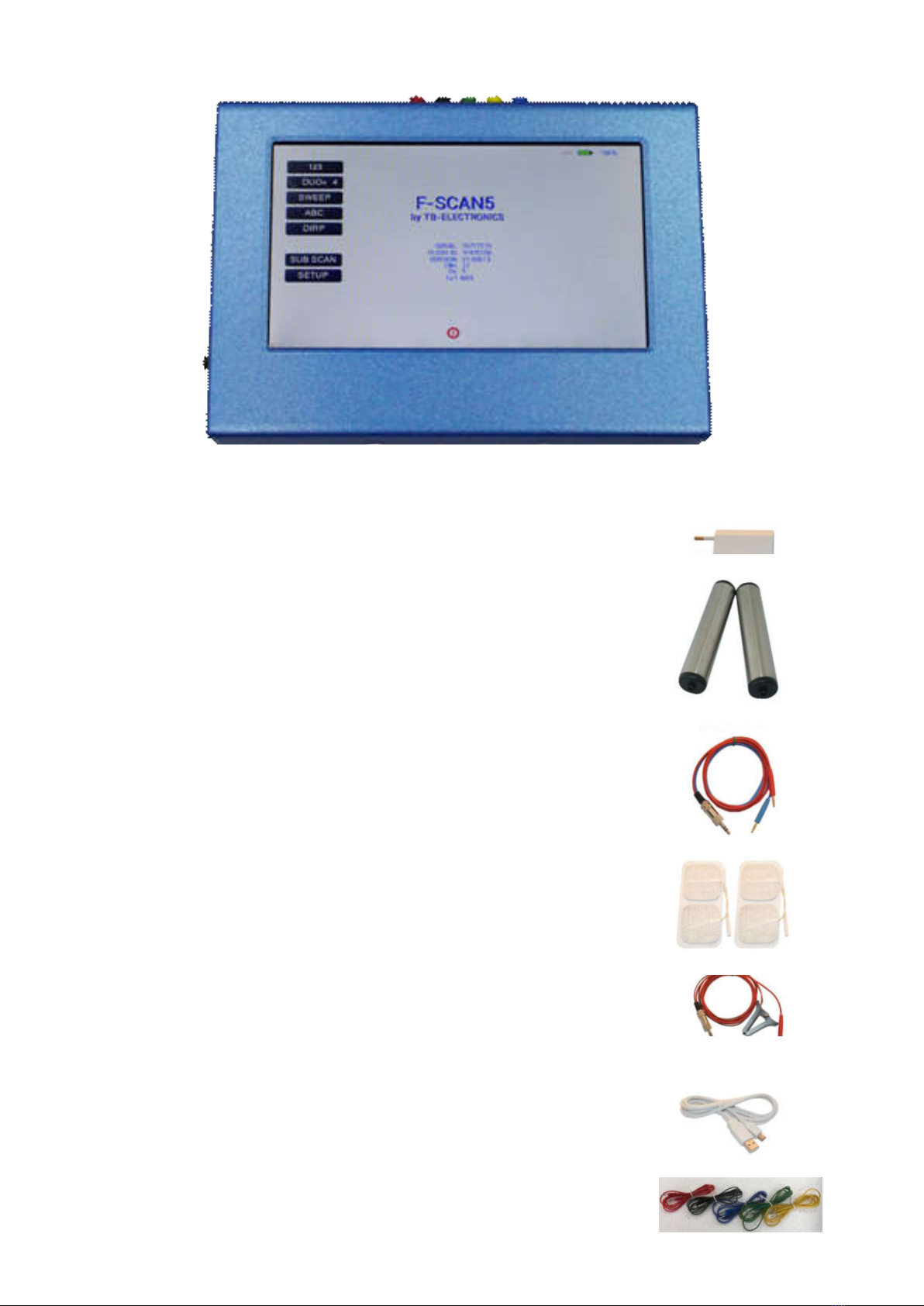
The shipment from the factory includes :
F-SCAN5 w ith instruction manual FTB135
Wall charger FTB224
Stainless steel electrodes FTB202A
Application cable for electrodes FTB308
5 sets of self-adhesive pad-electrodes FTB041
DIRP sensor FTB303
USB cable FTB223
Set of 5 cables f or 4 channel applications
- 6 -
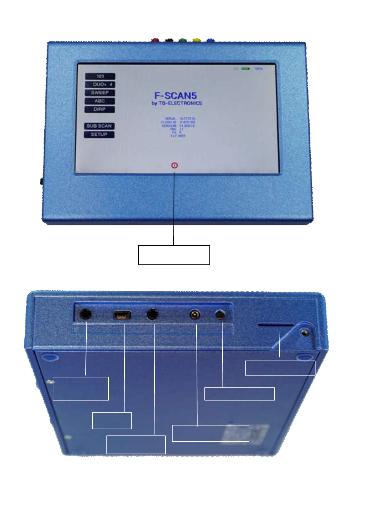
Elements for operation
A touch on this icon
switches the unit OFF.
CON2: WIDE
output port 15MHz
CON2: WIDE
Mini-USB
connector
CON1: Multi-signal
output port
CON3: PowerPort
ON switch
Slot for ChipCard

- 7 -
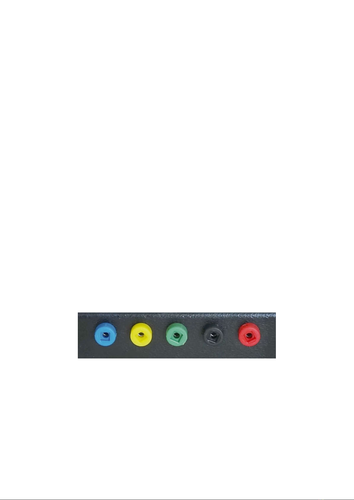
Colored plugs on top side of the device for multi-channel connections.
RED = channel A
BLACK = channel B
GREEN = channel C
YELLOW = channel D
BLUE = return line for all channels for current/conductivity measurement
The channels that are currently in use are indicated in the “DUO+” mode menu.
Signal forms delivered to Multi-signal-output port
SINE (DC-OFFSET)
10Vpp
Vpp
SQUARE, 0-symmetrical,
Full Wav e 0Vpp to 24Vpp
SQUARE, permanent positive, Half Wav e
0Vpp to 12Vpp (DC-OFFSET)
SMART, permanent positive, Half Wave
0Vpp to 12Vpp (DC-OFFSET), a high
frequency covering the application frequency.
- 8 -
Factory settings
Language on screen: English or German
Application time per frequency: 3:00 Minutes
(adjustable betw een 0:30 and 59:59)
Signal strength: 80% of maximum of 12Vpp
(adjustable +/- in steps of 1%)
Signal form: AUTO (Sine, Square Full Wave, Half Wave, SMART and OFF
selectable). AUTO = Square Half Wave if low er than 65000 Hz, Sine
above 65000 Hz.
Memory of ”123“ is empty.
Memory of “DUO+” is empty
Memory of ”ABC“ is empty and locked.
Connector 3.5mm CON1 :
At this connector is the standard multi signal output available w ith a bandw idth up to 3 MHz. Standard
application parts may be connected.
Connector 3.5mm CON2 :
At this connector is the WIDE output available w ith a bandw idth up to 15 MHz. Standard application parts may
be connected.
Connector 2.5mm on CON3 :
Connector for the Pow erPort. Application parts such as a laser pointer or magnetic field electrode must b e
connected here. No standard application part may be connected.
RESET: If device cannot be operated from the touch screen due to unknow n reasons, the RESET button on
the rear panel can be pressed shortly to shut dow n the unit. Use a “tooth pick” or “match” carefully.
Such effects may happen if the battery has not been charged correctly or a data transfer from softw are was
interrupted.
On top of device: 5 plugs red, black, green, yellow and blue (return/ground) for the 4 channel applications.

- 9 -
First steps to start F-SCAN5
- Connect the mini usb cable to the device and plug the w all charger into a w all outlet w ith a reading
betw een 100 VAC up to 240 VAC.
- Touch the ON sw itch on the side.
The screen must show the stand by screen w ith the battery symbol top right flashing yellow .
The information displayed means:
- SERIAL: Serial number of device
- ONS: Number of uses
- Ds Number of DIRPs
- FLASH ID: identifies the type of internal memory.
FFFFFFFF w ould indicate a memory defect. The device must then be checked by a
professional.
- V1.00B0x Version of software active in the device.
The opening screen, as show n above, offers a menu of 5 or 6 options. One has to be selected in order to
continue the setup of the F-SCA N5 for operation. The menu button EA P is enabled only if the device is
purchased w ith the EAP option.
- 10 -
The menu 123
The menu “123” must be used to create and run individual programs w ith the ability to enter random
frequencies in the range from 0.01 Hertz up to 15 MHz (Megahertz).
The F-SCAN5 offers 100 storage positions for programs of between 1 and 50 frequencies. The end of each
program is a value of 0 Hertz (Hz).
Each program can be named individually.
A number of parameters can be assigned to each frequency value:
- Run time (TIME)
- Signal form (Auto, Sine, Square Half Wave, Square Full Wave, SMA RT and OFF)
- WOBBLE (Output sw ings around the target frequency)
- ENV ELOP (Amplitude oscillates betw een 0Vpp and maximum)
- Amplitude (signal strength) of sine w ave and square wave.
All frequencies are listed on the right hand side of the display in groups of 10. If a frequency is a result of a
DIRP, the associated measured value (MV) is also indicated. The selected frequency is displayed in orange.
The vertical arrow s can be used to show up to 5 blocks of memorized frequencies of a program.
- 11 -
A touch on the icon “123“ opens the above menu:
The activated button turns green 123.
Displayed are:
- the program number “1“
- the program name “DIRP“
- the position of the frequency w ithin the program – betw een 1 and 50 – here ”1“. The left and right arrow s
can be touched to move to other frequency values of the program.
- “INS“ can be touched to shift the present frequencies to the right to insert a new frequency to the program.
- “DEL“ can be touched to eliminate the present frequency of 87000.00 Hz f rom the progra m.
- “CONT” can be touched to define a protocol or program w hich shall be used to continue an application. The
use of the CONT feature is explained in a special chapter.
- the total runtime of the program of 30 minutes “TT = 30:00“.
- the runtime of the present frequency in minutes : seconds on the below the “clock” icon w ith “03:00” (3
minutes and 0 seconds).
- the signal form selected “AUTO“.
- the icons “WOBBLE” and “ENV ELOP” remain inactive (their background is w hite).
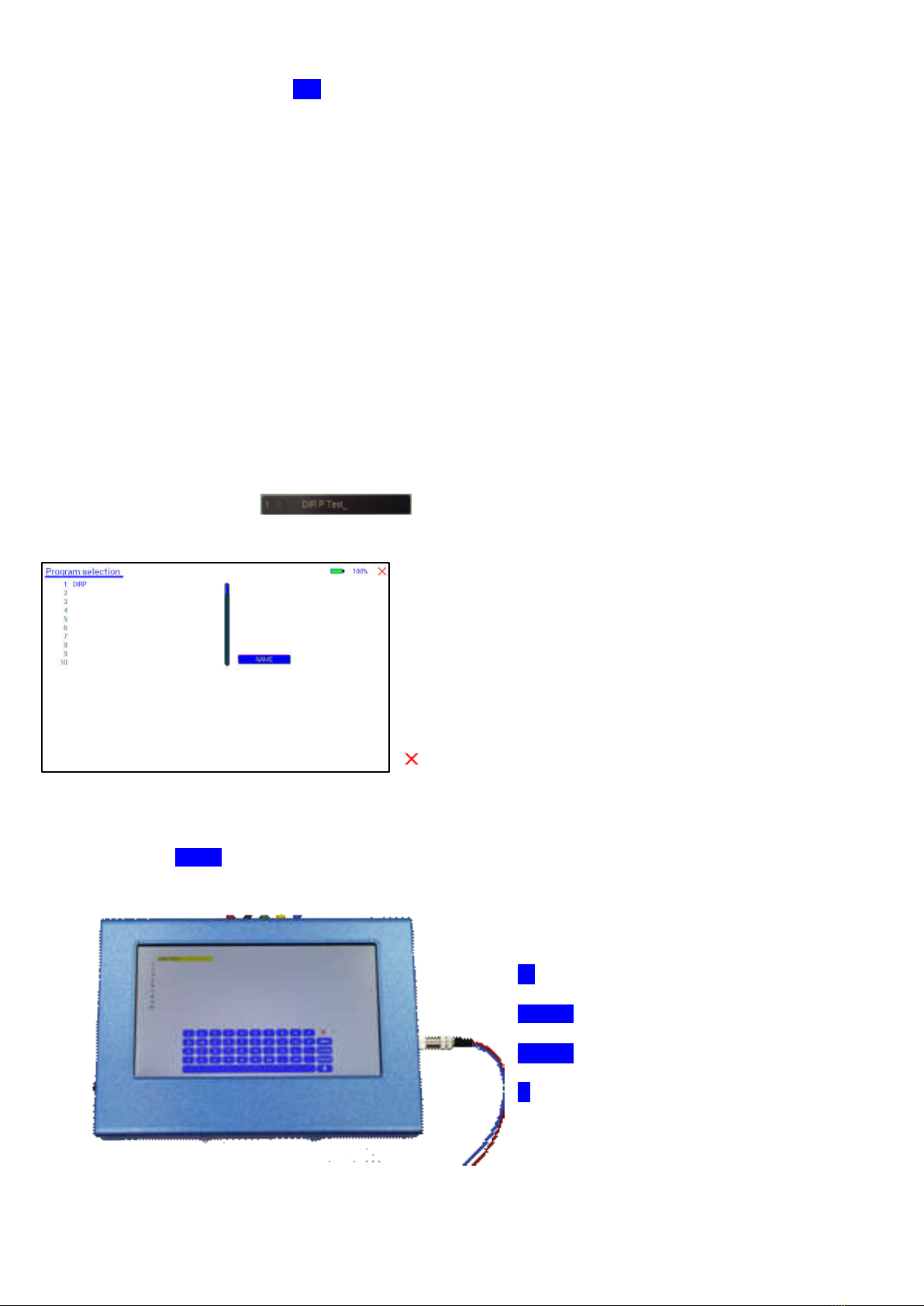
How to select a program from the menu “123“
A touch on the program bar
opens the submenu to select a progra m from memory, to edit a program name, or to add or delete a prog ram.
10 names of all programs stored in the memory block of 100
positions are displayed in the blue field. The present program
number and name are show n in blue. All other (unselected)
programs are show n in black. A cursor line is visible behind
the name.
The vertical scroll bar can be used to access program
positions 11 to 100.
A touch on the red cross in the upper right corner closes
this menu.
Any touch on a position 1: to 10: selects the associated program.
A touch on NAME opens the keyboard and it is possible to modify the name of the progra m w ith up to 20
characters.
X = close keyboard
= move left and erase
CLEA R = erase entire line
ENTER = close keypad and store new entry.
^ = sw itch to capital letters.
- 12 -
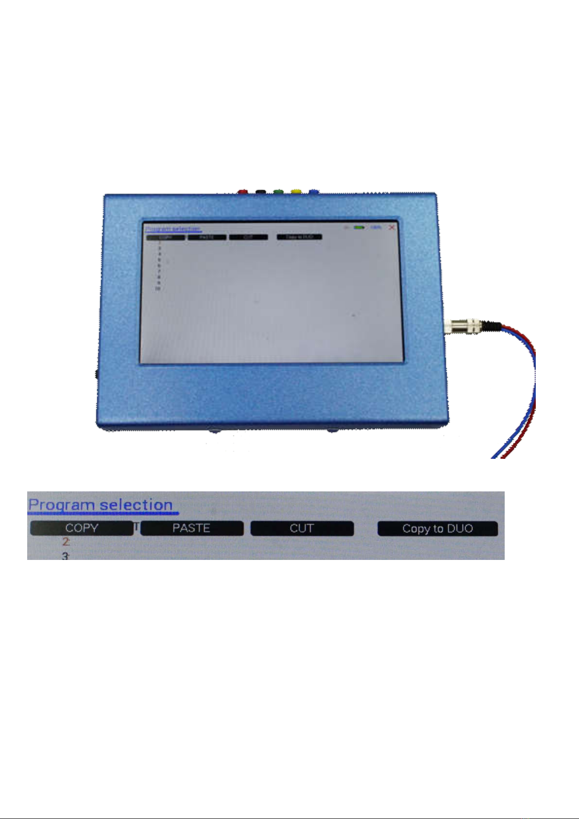
To cut, copy or paste an existing entry, just touch the program line and re main for approximately tw o seconds
until the “copy-paste-cut” sub menu opens.
After this, release the touch and proceed w ith the intended function.
COPY copies the entry into the paste buffer.
PASTE copies the contents of the paste buffer into a selected memory position.
CUT deletes the entry.
COPY TO DUO copies the selected program to the “DUO+” section so that a standard single channel program
can also be used as DUO, TRIPLE or QUA D application.
To close the “copy-paste-cut” sub men, press the X icon top right.
Exa mple for copying the entry from program 1 into program 5:
- touch program line 1 (here DIRP Test) and remain for 2 seconds
- when “copy-paste-cut-Copy to DUO” sub menu opens, release and press “COPY”.
- Select another program line, for example “5:” and keep it touched until the sub menu opens.
- Touch “PASTE”.
After this procedure, the program “1:” and program “5:” have the sa me name and contents.
- 13 -
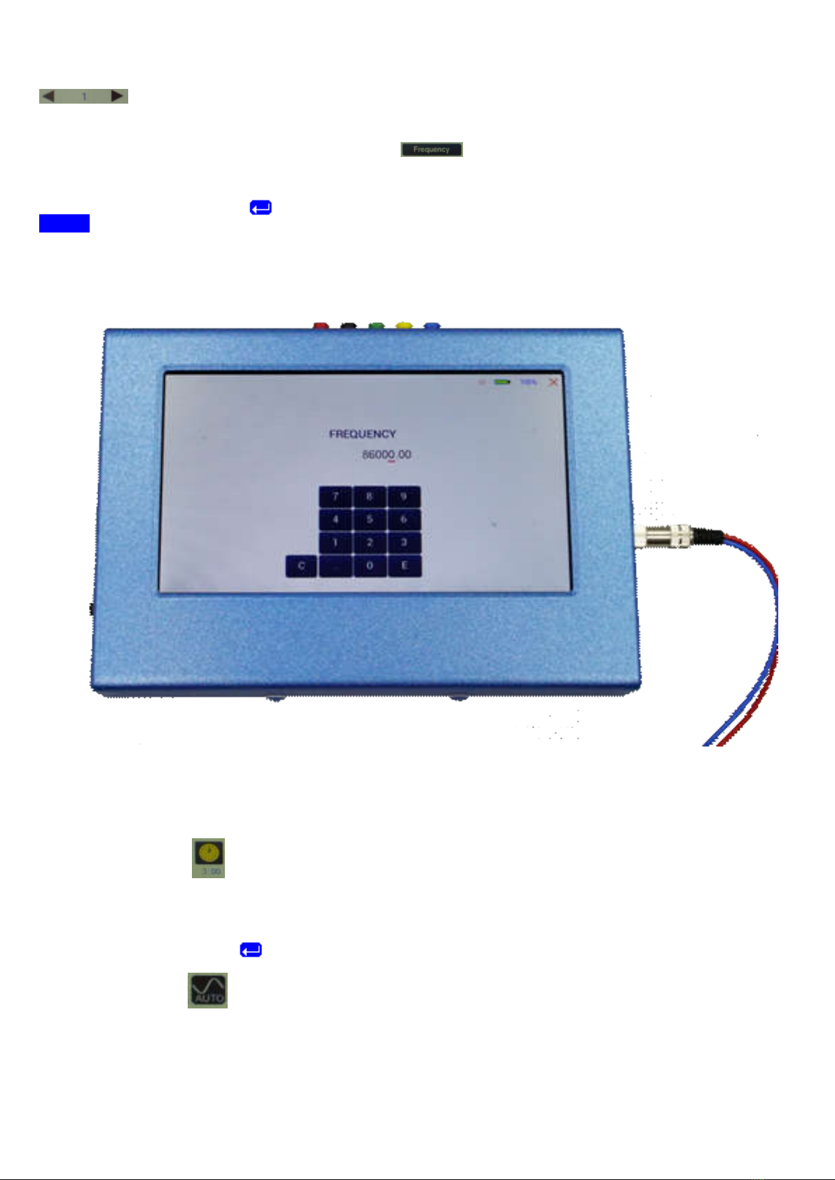
How to input a frequency value
The arrows in the menu “123“ are used to select the position (1 to 50) for the new frequency
value to be inserted in the opened progra m.
Next, the present frequency value has to be touched
A numerical key block opens and the new value can be entered.
A touch on the ENTER-key saves the input
CLEA R sets the entry to 0.
X = close numerical key block
The properties of frequencies
Runtime
The factory setting of the runtime per frequency is 3:00 minutes. It can be changed after a touch on the above
icon and the input of the minutes and seconds to be applied.
A touch on the ENTER-key saves the input.
Signal form
The signal form delivered to the “OUTPUT PORT“ can be sw itched from AUTO to SINE, SQUARE HALF
WAVE (DC-OFFSET), SQUARE FULL WAVE, SMA RT or OFF w ith successive touches on this icon. The
setting AUTO delivers SQUARE HALF WAVE (DC-OFFSET) signals w ith frequency values below 65000 Hz
and SINE signals w ith values above 65000 Hz. The currently delivered w ave form is indicated in the icon.
- 14 -
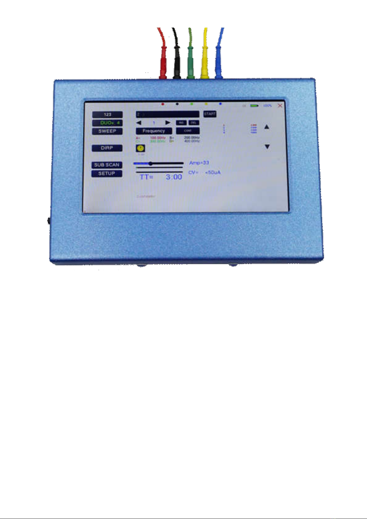
The menu DUO+
The menu “DUO+” must be used to create and run individual programs w ith the ability of entering random
frequencies in the range from 0.01 Hertz up to 15 MHz (Megahertz). Depending of the mode, tw o, three or f our
frequencies are output simultaneously w hen a program is activated w ith START.
The button DUO+ w ith the number indicates how many channels are in use.
DUO+ 2 indicates tw o channels and the red, black and blue output plugs on the screen show where to connect
the application parts.
DUO+ 3 indicates three channels and the red, black, green and blue output plugs on the screen show where to
connect the application parts.
DUO+ 4 (as in the image) indicates four channels and the red, black, green, ye llow and blue output plugs on
the screen show where to connect the application parts.
NOTE: the blue plug is used for conductivity measurement and is needed only f or this. If no measurement is
necessary, the blue connection is not necessary.
The F-SCAN5 offers 100 storage positions for programs of between 1 and 50 frequencies. The end of each
program is a value of 0 Hertz (Hz). This means, that in DUO mode w hen tw o frequencies are output
simultaneously, 25 sets of tw o are in use. In TRIPLE mode its 16 sets and in QUAD mode it is 12 sets.
Each program can be named individually as already described in the chapter “The menu 123”.
In DUO+ mode, it is not possible to set properties such as WOBBLE, ENV ELOPE or w aveform.
The program selection in DUO+ mode w orks in the same w ay as in the chapter “The menu 123”.

- 15 -
To cut, copy or paste an existing entry, just touch the program line and remain for approximately tw o seconds
until the “copy-paste-cut” sub menu opens.
After this, release the touch and proceed w ith the intended function.
COPY copies the entry into the paste buffer.
PASTE copies the contents of the paste buffer into a selected memory position.
CUT deletes the entry.
COPY TO 123 copies the selected program to the “123” section so that a multi channel program can be used
also as a single channel application.
To close the “copy-paste-cut” sub men, press the X icon top right.

- 16 -
Current indicator and OSCA for the “123 menu”
The bottom bar graph displays the measured value of the electrical current w hich flows through the output at
connector CON1. The current flow for non-linear “loads” is dependent from
- the electrode type
- the frequency
- the w ave form
- the selected amplitude
This value gives a real feedback of the electrical “load” at the output. The current indicator is used for the
OSCA function w hich controls the output amplitude at the optimum value.
If OSCA is selected in the setup menu, the amplitude slider and current indicator are displayed diff erently:
The amplitude cannot be modified any more. As long as the current measuring system does not “see” a valid
current flow ing, the amplitude is set to a standard of 60%. As soon as a valid current is measured, the
amplitude is automatically controlled by the algorithm w hich is dependent of the OSCA level. This level c an be
set to
- SENSITIVE
- STANDA RD
- HIGH
- MAX
It is recommended to use “SENSITIV E”.
How to start, pause, or stop a program
Touch the icon STA RT to start a program.
Touch the icon PA USE to initiate a pause.
Touch the icon STOP to end a running program.
Any attempt to change the menu w hile a program is running w ill cause the system to return to menu “123”
immediately.

- 17 -
The menu SWEEP
A touch on the icon “SWEEP“ opens the screen to start the broad band frequency sw ing “SWEEP“.
SWEEP can be used to sw ing through a broad band of frequencies betw een a low er limit “Fmin” and an upper
limit “Fmax” for a limited time (standard 20 minutes).
The step size “DELTA F” from value to value is defined automatically. “Fmin” and “Fmax” can be set by
touching the icons Fmin and Fmax.
The signal form is “AUTO”, w hich means “SQUARE DC-OFFSET” through 65000 Hz and “SINE” above that
value.
The amplitude is as selected in menu “123”. If OSCA is set, the amplitude is set to 60%. To modify the
amplitude, OSCA must be turned off.
The red and blue marking on the right side of the screen indicates the output w hich has to be used.
Touch the button icon START to start the procedure. The output moves from “Fmin“ up to “Fmax“, turns
around to move back to “Fmin, and so on, until the time of 20 minutes is up. The activity is simultaneously
displayed on the screen.
A touch on the icon STOP stops the procedure at any point.

- 18 -
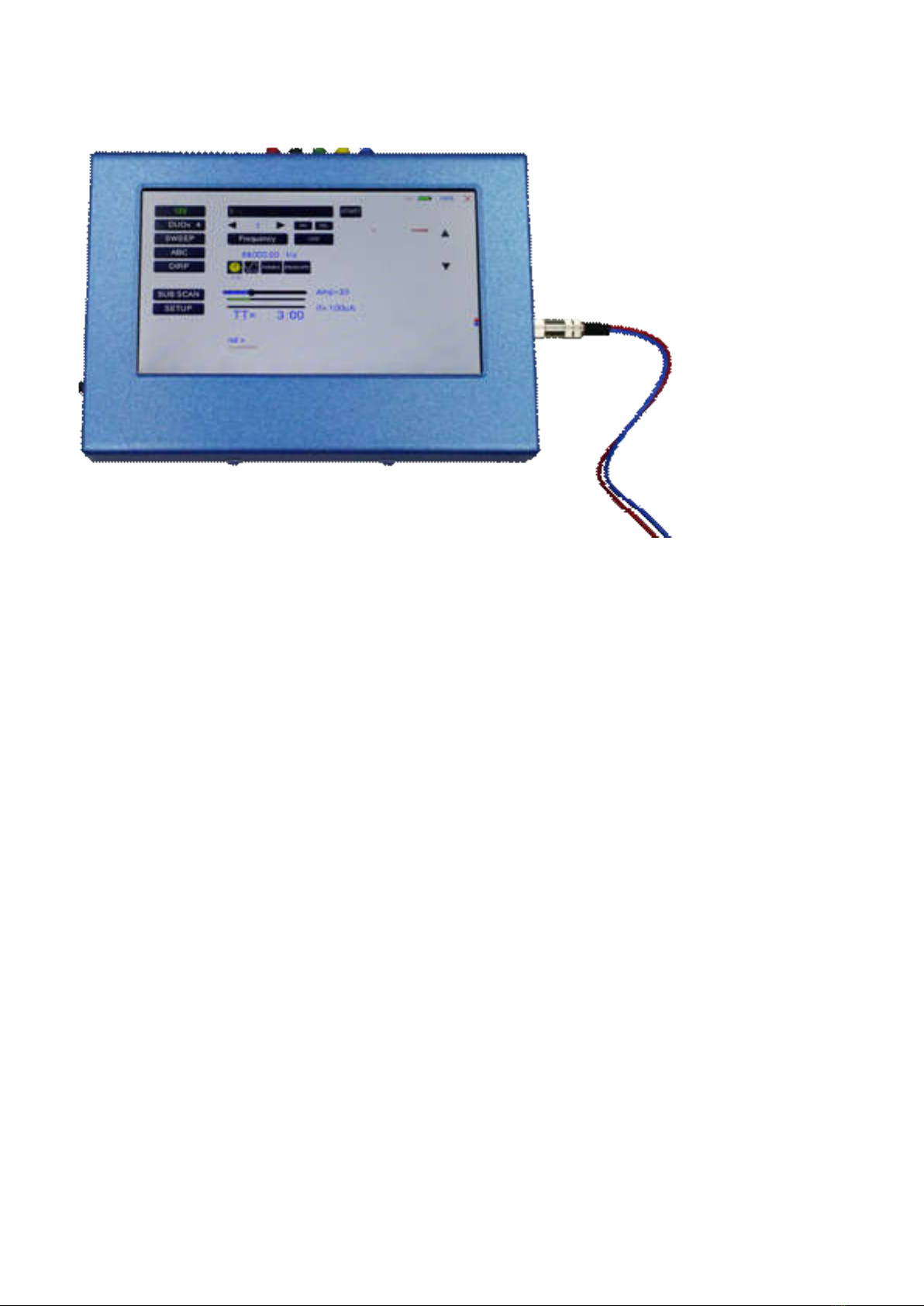
The menu DIRP
A touch on the button DIRP opens the screen for the automatic resonance analysis “DIRP“.
“DIRP” stands for: Dual Integration Resonance Procedure
“DIRP” registers resonances to frequencies applied in steps of “DELTA F” w ithin the limits betw een a lower
value “Fmin” and an upper value “Fmax”.
SINE signals w ill be assigned automatically for the analysis. IMPORTANT: THE A MPLITUDE SETTING MUST
BE ASSIGNED WITH THE AMPLITUDE SLIDER. IT IS RECOMMENDED TO SET THIS VALUE TO 100% TO
ACHIEV E RESULTS THAT CAN BE COMPA RED. ONLY IN CASES OF HIGH SENSIBILITY, USE LOWER
VALUES FOR THE AMPLITUDE.
OSCA HAS NO EFFECT ON DIRP.
The red, black and blue marking on the right side of the screen indicates the output that has to be used w ith
the finger sensor FTB303.
The analysis is based on tw o readings:
1. MV = Measured Value of a resonance
2. CV = Conductivity Value
The Conductivity Value is a personal constant of the individual analyzed. It should read betw een 5% and 25%
as a base for useful results of the analysis. The Measured Values are show n as a green vertical bars or lines
in the graph.
After completing a “DIRP” run, the algorithm calculates the level of a horizontal line (violet) in the graph, called
the Clipping Level = CL. It separates the 10 highest resonance peaks (HITS) of the graph from the rest. If
required, the CL line can be moved up or dow n manually.
Fmin touch to set “Fmin“ (Range 50 Hz to 2 MHz)
Fmax touch to set “Fmax“ (Range 50 Hz to 2 MHz)
Delta F touch to set “DELTA F“ (range 1Hz to 10000 Hz)

- 19 -
RECALL touch to recall a previously stored complete “DIRP“ analysis from temporary memory.
SAVE touch to assign the previously made DIRP to the selected program.
Exa mple of a “DIRP“ analysis recalled from memory:
The display on the screen shows all details of the recalled analysis, including the settings for “Fmin”, “Fmax”,
“DELTA F” and the Clipping Level “CL = 13” (the violet line), w here it separates 10 HITS ( measured values of
resonances) from the remaining graph.
You can use the arrows to load a program.
Touch to move w ithin the graph in the direction of Fmin to read the CV, MV and CL of
individual resonances.
Touch to move w ithin the graph in the direction of Fmax to read the CV, MV and CL of
individual resonances.
Touch to move the violet line upw ard, thereby reducing the number of HITS (MVs).
Touch to move the violet line dow nward, thereby increasing the number of HITS (MVs).
Touch to vertically zoom the graph in steps from 0.0 to 2.0 to improve the reading. The
Clipping level w ill be recalculated to match the moves. Default setting of zoom is 1.0.
DELETE Clear graph.

- 20 -
How to prepare for a DIRP and run it
The settings show n on page 18 of this manual can be used to perf orm a DIRP analysis in the frequency range
betw een 80000 Hz and 560000 Hz:
1. Attach the DIRP sensor FTB303 follow ing the instructions shipped w ith it to connector OUT as
indicated on the screen (red, black and blue circles).
2. Connect the red w ire to the cylinder. Hold the cylinder in the left hand.
3. Touch the button START to start the analysis
4. Wait until the graph line reaches Fmax and completes the procedure. Touch the button STOP to
end the analysis at any point. During a DIRP procedure, the reaction time of a touch may take up to
1 second.
5. Touch the button SAVE to store the co mplete DIRP results in the selected program position. This
will overwrite any data previously stored in that position.
This manual suits for next models
1
Table of contents


