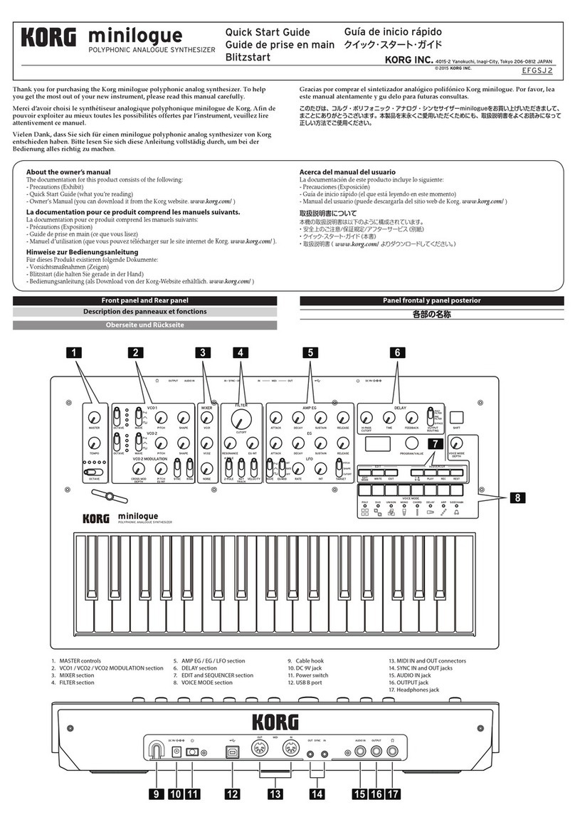
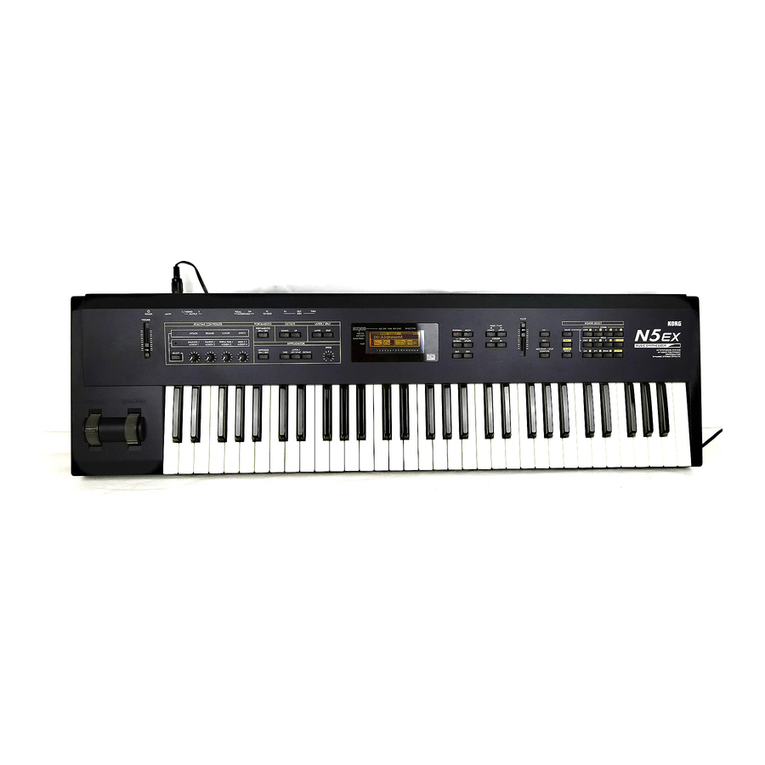
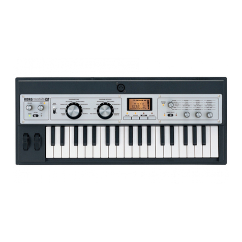
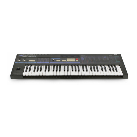
Korg POLYSIX User manual

POLYSIX
CONTENTS
1.
SPECIFICATIONS
.
2.
STRUCTURAL
DIAGRAM
.
3.
BLOCK
DIAGRAM
.
4.
CIRCUIT
DIAGRAM
..
5.
PC
BOARD
.
6.
CONNECTOR
FUNCTION.
7.
SEMI-FIXED
RESISTORS
DIAGRAM
8.
ADJUSTMENT
PROCEDURE
.
9.
PARTS
LIST
.
1
2
3
4
5
17
18
19
24
PROGRAMMABLE
6VOC
SYNTHESIZER
SERVICE
MANUAL
KEIO
ELECTRONIC
LABORATORY
CORPORATION
TOKY
O
/JAP
AN

1.
SPECIFICATIONS
KEYBOARD
.
•
61
keys
(C
-
C)
VOICES:
6
(Program
and
edit
functions
are
possible
for
items
marked
*)
vco
*.
SUBOSCILLATOR*
VCF*
.
ENVELOPE
GENERATOR*.
VCA*...
MODULATION
GENERATOR*
EFFECT*.
KEY
ASSIGN
MODE
.
ARPEGGIATOR
.
TUNE
.
BEND
.
OUTPUT
.
PROGRAMMER
TAPE
INTERFACE
CONTROL
WHEEL
x
2
INPUT
JACKS
.
OUTPUT
JACKS
DIMENSIONS
.
WEIGHT
.
ACCESSORIES
INCLUDED
POWER
CONSUMPTION
•
Octave
Selector
(16',
8',
4')
•
Waveform
(
[\
,
PW,
PWM)
•
Pulse
Width/PWM
Sensitivity
Adjustment
•
PWM
Speed
•
Off
•
1
oct
Down
•
2
oct
Down
•
Cutoff
Frequency
Adjustment
•
Resonance
Adjustment
•
Envelope
Generator
Modulation
•
Sensitivity
Adjustment
•
Keyboard
Tracking
Adjustment
(0
~~
150%)
•
Attack
Time
•
Decay
Time
•
Sustain
Level
•
Release
Time
•
Mode
Switch
(EG,n_)
•
Attenuator
(~10dB~
+10dB,
11
Steps)
•
Frequency
•
Delay
Time
•
Level
•
Modulation
(VCO,
VCF,
VCA)
•
Mode
(Off,
Chorus,
Phase,
Ensemble)
•
Speed/Sensitivity
Adjustment
•
Poly
•
Unison
•
Chord
Memory
•
Hold
•
Speed
•
(0.4Hz
~
40Hz)
•
Range
(Full,
2
oct,
1
oct)
•
Mode
(Up,
Down
Up/'Down)
•
Latch
(On/Off)
•
Arpeggio
(On/Off)
•
±50
Cents
•
Sensitivity
Adjustment
(MAX
±1300
Cents)
•
Level
Selector
(Off,
Low,
High)
•
Volume
•
Bank
(A,
B,
C,
D)
•
Program
(1
~
8)
•
Write
(Enable,
Disable)
•
Switch
(Enable,
Disable)
•
To
Tape
•
From
Tape
•
Verify
•
Error/Cancel
•
Tape
Indicator
x
2
(Found,
Loading)
•
Bend
•
MG
•
From
Tape
(With
High/Low
Switch)
•
Chord
Memory
Qgno)
•
Arpeggio
Trigger
In
(1
•
VCF
fcM
In
(-5V
~
+5V)
•
To
Tape
(With
High/Low
Switch)
•
Headphone
•
Output
•
980
(W)
x
373
(D)
x
132
(W)
mm
•
11.5kg
•
Connection
Cord
®
Plug
Adaptor
(Phone-To-Mini)
•
Memory
Cassette
•
Voltage
(Local
Voltage
50/60
Hz)
Wattage
(25
W)


EFEECT
OFF
CHORUS
PHASE
ENSAMBLE
ATTENUATOR

4.
CIRCUIT
DIAGRAM
KLM-366
KEY
ASSIGIMER
(OLD
PRODUCTION)
4

KLM-366
SYNTHESIZER
(OLD
PRODUCTION)
5

KLM-366
{NEW
PRODUCTION)
(KLM-366
includes
KLM-396)
i-*
co
O-J
HNd
O
-l
TO
KLM-368
TO
"
KLM-376
6

KLM-367
cm
t
TO
KLM
-
30?
GND
(cWTTT
)—i
DATA
^
tCNIl-2
ICS
>/2
393
CN03
TO
KLM
-368
DIO
D9
\
m
IC22
MPD804-8C
C22
10P
C
E
C23
22
P
CE
if?
□
+
5V
XI
6
MHZ
40
26
20
DU
CN02
TO
KLM-376
10U,
DBO
TO
DB
1
DB2
XTALI
DBS
XTAL2
DB4
DBS
Vcc
DB6
DB7
Vdo
P10
PH
PI2
Vss
P13
P/4
EA
PI5
P16
PI
7
SS
ALE
NR
REST
RD
Tnt
P20
P2I
Tl
P22
P23
P24
P25
P26
P27
+
/5V
(CNOZ-'iy
16
V
x
4-
C
(C3I,
C38
C39,
C4-I)
O.OtyuCE
x
4
+
5V
C7&
0
CN02-2)
-
&N
D
d
(CN
02
-
3
)
-
■
-5V
C2
(C
NO
2-43
-
-
15
V
66
4
*
0CN02-S
)
—
GNDA
(
CN
02
-
6
)
—
+
SVA
(CN
02
-
7
)—
+
5V
~rh
\-5V
-15
1
/
•
\+5VA\
CN08
TO
REAR
PANEL
IC2I
13600
339
©
+5
7
2-5
IC5
393
IC6
393
1C20
13600
©
f
15
©
-
1
5
®
+
5
@
6ND
©
+
/5
®-15
®
*-5
©
-5
——
(CN05
19)
CNO-5
TO
KLM-
366
7

KLM-368
EFFECT

SE

KLM-376,
375
425
POWER
SW
KLM-372AI
rFUSE.
T
T
CN
2
0
O
SPA
R
K
KILLER
Ptiizm
nsn
OR
I
A/YE
ZbSPjCPH
I
<S—<§!
i
TA-OOI
T8-001
OP
I
TA-005
T3-005
KLM
-
4
25
I
SPARK
KILLER
POWER
TA-005
T3-C>05
KLM”37
6A
—
RS
FUSE
1A
FUSE
1A
D2,3,4,5
---1S-1885
D1
LED
LT8001P
TH1
THERMISTOR
TD
5
-
A
150
DA
TA
TB
VOLTAGE
100
V
120
V
220V
240V
3
BROWN
ORANGE
YELLOW
GREEN
4
WHITE
WHITE
NC
ORANGE
BROWN
GREEN
YELLOW
ogllAv
2>SB744AP^a
2S/\733
I—.iB
R15
7|
►
——-VW-f-"——
130n
+
+C11
zC14
A:
zzICf
4700
£12
2
$
CE
1
I
c
2
M5230L
+
I
+C
6
LC13
=L
zzio
220
Qg
C7
nPj
-
3
5
V
0.0
^
Cc
4
--A/W-i-
—
R
4
130n
Q7
2SC945
R12
0.5ii
1/2w
Q3
2SD794APpi.Q
CN01(BR)
^
TO
KLM-366
+Mj—CHEDl
Tgvl
—
fflfT)
R13
C8
243n
IJt.
196
^qV
CIO'
100^
A
R3
_
47.K
_
Q
2
TSfl
R2
y
2SD794A
IfiF
r-
-—«
>r-.
"at
C
10
F"
t
D
1
i
IS
>243
cvj
CM
gfot-
,
>CM>,
5
^
>
S
<
a
k
1+15V]
I
Q5
1
6rT0
<
2SC945
^\72R6
■
'
C
4
“
IC
1
0.0
Im-
2
p
1/2
455?
CE
JIG
C5
I
I
100
GND
16
v
Ignd
A^
EIv^dedI
CN02CRE)
|
TO
KLM-367
-615V
—
002-1)
|
;9
Efg
Ci
)>
A
ic
10O
R9
R5
VR1
4.87K
3.24
ft
fo[££L.220
a
1
%
T
^
v
'“cw
vV
''
2r^
-
G
ND]
.
.
GND
A'
IC1
1/2
4555
R4
,-^niK
HA
I
Q
6
rrEn
42SA733
CS
r—
1
T(
0.0
I
‘
bAc2
I
e
zzz
iOOA'
[7
!
A
tei
CN13
CGY)
TO
KLM-369
-/
*—4^VVW-
Q1
P<*^
2SB744A
i
P
j/2w-
CN15
(BlO
TO
KLM-368
F15V
GND
CONNECTOR
10


1Z3DEXZM
p.
YY
So
DO
2
6.
D03
CH05
*?P

KLM-368
EFFECT
CNI4
Z
(3
m
PS
m
m
«-
CNiS
*j
N<<*
R|
15
">?
VW
.VR8
CNI6
LEVEL
^
324
R
1
®6
-1
AAAr
RIOS
IQ
“VvV
_/R
I
AAAr
C80A
™
__
:
vw
R
I
55
■
VvV
R
156
-AAV
R
I
8
I
-AAAr
R
I
82
■
VvV
R
I
83
wv
R
I
84
c)
-VW
J
S?0
»
D24
"V
„
025
R
43
K_____V
AW
C27
R44
_VvV
Q2
VW
C3
I
/
"
'
\
R4
a
(
)
AAAr
—w
5
c
r
:cdi
l
)
VW
CI8
—-'
R
9
I
^AV
VW
AAAr
WV
18
RIO
I
VW
«|
R
I
14
C82
VW
Rise
VW
R
189
—
■
—
JS8
VW
Rf
90
VW
R
I
23
VW
AW
VW
"x
R25
VW
"X
R45
AAAr
vw
R26
vw
R93
R92
VW
J2S
VW
R28
J29
R94
AAV
R96
C66
AAAr
1
■
(—)
vw
Vo
'R97
R227
VW
•
(
)QI9
(
^vw
-
R95
vw
■
AAAr
R
I
2
AW.
R32
AAAr.
8
C79
R
1
70
AAAr
AW
R
I
32
R
I
35
Vw
R72
VW
R73
AAAr
P^-
11—J
TP2
R55
AAAr
O
R54
VW
5
C35/\
j
R74
AAV
R1&
D
M
R
AAAr
AAAr
R
I
36
R
I
73
AAAr
R
I
78
VVV
R
!
76
VW
AAAr
^
7
AAAr
J40
CC^
CK'
R
(Of
AAAr
R
102
VW
r
103
<n
<n
AW
R209
VW
R2
I
0
VW
CN03
vw
R
I
40
VW
R
I
4
I
-AAAr
R
I
79
J48
+
R
§5^
IC9
s
fSsTi
o
AAAr
AAV
AAV
105
RI
20
RI
43
AW
gWV
vw
R
I
46
VW
gWV
vw
AAAr
R84
vw
R2I6
13


KLM-
372
KLM-396
Oq
a
gy
Q
N
UJ
<
3
X
H
a
g-
o
h-
A-
00
9£
z
£<
2<
2z
f—
CD
Dh
<q
Oh
i
*
3
uj
3
.
O—
1
UJ
oz
H
o
a
uj
a.
UJ
2
UJ
O
<
tJLi
O
CD
tn
CM
UJ
a
>
H
UJ
2
<
co
UJ
X
H
CL
>
uj
a
a
uj
CO
a
Hi
ll.
H
iii
uj
a:
ll
a.
>
LU
o
<
UJ
CO
3
Ll,
TH
a
LaJ
UJ
H
3
UJ
COS
CO
<
<
n
©s
$il»
8
ss*»
q
cr
UJ
z
a
<r
z
9
Z
L
,
Ouj
r*
h
a
LaJ
Q»*»
t
UJ
1"*“
Z
ZD
uj
a
z
.Q
UJ
UJ
1x1
^
z
a
uj
uj
a
o>
<£
j—
o
r
1
Z
9:
X
o
hiD
y
a
•“
co
UL
LjJ
3
O
CO
a
co
UJ
uj
a
z
a
uj
3
§—»
CO
z
52
a
O
<
<
QJQ.
a
2
uj
a
UJ
UJ
UJ
O
UJ
m
co
3
.
a
UJ
a
__
—
UJ
LD
<
a
ZD
<r
uj
OCL
Q
!2>*
CD
TO'
NC
KLM-425
16

6.
CONNECTOR
FUNCTION
P.C.B.
TO
CONNEC¬
TOR
COL¬
OR
P.C.B.
CONNEC¬
TOR
FUNCTION
TO
CONNEC¬
TOR
COL¬
OR
P.C.B.
CONNEC¬
TOR
FUNCTION
P.C.B.
TO
CONNEC
TOR
COL¬
OR
,,
10
KLM-369
11-
4
C
■
5
,,
KLM-371
J35
1
D07
KLM-371
J35
1
>>
9
<<
5
INH1
6
>
■
2
PI
2
-3
"
2
"
8
<•
6
IN
H2
7
3
+5
..
3
7
"
KLM-369
13-
1
+
15
■
M
™
ns»
13-
1
GY
4
GND
n
4
KLM-366
6
GR
2
+5
2
</
5
TE
/.
5
"
5
"
3
GND
"
3
KLM-376
01-
1
+15
KLM-366
01-
1
BR
"
4
4
-5
"
4
>
■
2
+5
"
2
•
>
"
3
"
KLM-369
13-
5
-15
KLM-376
13-
5
GY
3
GND
"
3
,,
"
2
••
KLM-369
15-
1
NC
KLM-368
15-
3
BK
4
-5
"
4
>
■
"
1
"
2
GNDA
"
2
KLM-376
01-
5
-15
KLM-366
01-
5
BR
KLM-369
06-
1
BL
3
SIG
IN
"
1
'
■
6
GNDA
-
6
"
2
"
KLM-369
201-
1
INH-1
KLM-370
201-
1
7
+5
»
7
,,
"
3
"
;
2
DATA
„
2
KLM-376
02-
1
+
15
KLM-367
02-
1
RE
"
4
"
3
A
„
3
2
+5
n
2
,,
"
5
"
4
B
,,
4
3
GND
./
3
,,
"
6
"
5
C
„
5
4
-5
..
4
,,
"
7
6
GND
n
6
5
-15
u
5
,,
"
8
7
-5
„
7
6
GNDA
"
6
,,
"
9
8
+5
,,
8
7
+5
„
7
,,
"
10
"
9
P10
1,
9
KLM-376
13-
1
+
15
KLM-369
13-
1
GY
REAR
BR
10
P11
,,
10
2
+5
2
,,
PANEL
RE
11
PI
2
11
3
GND
,,
3
,,
"
OR
12
PI
3
,,
12
4
-5
4
,,
"
—
13
D03
,,
13
5
-15
5
,,
KLM-371
10-
1
BR
14
D02
,,
14
KLM-376
16-
1
+
15
KLM-368
16-
1
BK
-2
"
2
RE
15
KBD-TRACK
•
•
15
2
GND
-
2
"
3
OR
KLM-370
201
-
1
INH-1
KLM-369
201-
1
3
-15
"
3
"
4
YE
2
DATA
,,
2
"
5
GR
3
A
,,
3
"
6
BL
4
B
,,
4
"
7
PU
5
C
,,
5
"
8
GY
6
GND
,,
6
"
9
WH
7
-5
7
"
10
BK
8
+5
„
8
"
11
BR
9
P10
„
9
"
12
RE
10
P11
,,
10
"
13
OR
11
P12
,,
11
"
14
YE
12
PI
3
,,
12
"
15
GR
13
D03
„
13
"
16
BL
14
D02
,,
14
"
17
PU
15
KBD
TRACK
„
15
KLM-369
PU
11-
1
PU
KLM-371
10-
1
D03
KLM-367
10-
1
BR
2
2
D02
"
2
RE
Q
3
DOI
"
3
OR
4
DOO
"
4
YE
5
5
P13
"
5
GR
a
6
P12
"
6
BL
KLM-367
03-
7
OR
7
P11
"
7
PU
6
8
P10
"
8
GY
5
9
D04
«
9
WH
4
10
D05
"
10
BK
3
11
D06
"
11
BR
„
2
■
r
'
12
D07
"
12
RE
13
P26
"
13
OR
KLM-366
14-
1
WH
14
P27
"
14
YE
?
15
+5
11
15
GR
3
..
16
GND
"
16
BL
KLM-369
15-
3
BK
17
TE
"
17
PU
„
2
,,
KLM-371
12-
1
ARPE
KLM-366
12-
1
BR
,,
1
,,
2
POLY
"
2
RE
KLM-376
16-
1
PI
3
UNISON
"
3
OR
,,
2
4
CHORD
"
4
YE
„
3
n
5
HOLD
"
5
GR
KLM-367
06-
1
BL
6
PI
7
"
6
BL
,,
2
ii
7
P16
"
7
PU
,,
3
,
,
8
PI
5
"
8
GY
,,
4
,,
9
P14
"
9
WH
,,
5
„
10
P13
"
10
BK
6
ti
11
PI
2
"
11
BR
,,
7
12
P11
"
12
RE
}
,
8
13
P10
..
13
OR
9
14
P20
<•
14
YE
ff
10
15
P21
15
GR
REAR
BR
16
ACKR
"
16
BL
PANEL
RE
17
ACKI
"
17
PU
„
OR
KLM-371
J3
1
+5
KLM-371
J3
1
NOTE
„
YE
2
GND
-
2
/<
GR
3
ARP
»
3
BROWN
-»
BN
PURPLE
-+
PU
CONTROL
BR
4
POL
4
PANEL
RE
5
UNI
"
5
RED
->
RD
GRAY
-+
GY
„
OR
6
CH
6
„
YE
7
HO
7
ORANGE
^
OR
WHITE
->
WT
,,
GR
8
P17
"
8
„
BL
9
P14
9
YELLOW
->
YE
BLACK
-+
BL
KLM-367
11-
1
PU
10
P12
"
10,
,,
2
„
11
P11
11
GREEN
->
GR
PINK
-*
PK
,,
3
„
12
P10
12
"
4
13
P20
"
13
BLUE
->
BU
LIGHT
BLUE
-+
■
LB
P.C.B.
CONNEC¬
TOR
FUNCTION
P.C.B.
TO
CONNEC¬
TOR
COL¬
OR
P.C.B.
CONNEC
TOR
FUNCTION
KLM-366
KLM-366
KLM-366
KLM-366
KLM-366
KLM-366
KLM-367
KLM-367
KLM-367
01
-
1
2
3
4
5
6
7
04-
1
2
3
4
5
6
7
8
9
10
11
12
13
14
15
16
05-
1
2
3
4
5
6
7
8
9
10
11
12
13
14
15
16
17
18
19
12
-
1
2
3
4
5
6
7
8
9
10
11
12
13
14
15
16
17
14-
1
2
3
1
2
3
4
1
2
3
4
5
6
7
03-
1
2
3
4
5
6
7
05-
1
2
3
4
5
6
7
8
9
17-
02
-
+
15
+5
GND
-5
-15
GNDA
+5A
PI
7
P16
PI
5
P14
PI
3
PI
2
P11
P10
DB0
DB1
DB2
DB3
DB4
DB5
DB6
DB7
IR
8
'
4'
ST
TE
KBDTRACK
VCF
MOD/CUTOFF
VCO
MOD
PW/PWM
EG
INT
RESO
ATTACK
DECAY
SUSTAIN
RELEASE
,/T
SUB
1/2
SUB
OFF
EG
MODE
ARPE
POLY
UNISON
CHORD
HOLD
PI
7
P16
P15
PI
4
PI
3
PI
2
P11
P10
P20
P21
ACKR
ACKI
SIG
OUT
GND
A
NC
ACKI
(IN)
CHORD
Fc
MOD
IN
ACKI
(OUT)
+15
+5
GND
-5
+
15
GNDA
+5A
EFF-SP/INT
CHO
PHA
ENS
VCA
MOD
P-VOL
RESO
EG
MODE
SUB
OFF
SUB
1/2
y\
RELEASE
SUSTAIN
DECAY
ATTACK
RESO
KLM-376
01
-
BR
KEY¬
BOARD
KLM-367
KLM-371
KLM-368
REAR
PANEL
KLM-376
KLM-368
KLM-366
05-
19
18
17
16
15
14
13
12
11
10
9
8
7
6
5
4
3
2
1
12
-
1
2
3
4
5
6
7
8
9
10
11
12
13
14
15
16
17
14
-
1
2
3
02
-
1
2
3
4
5
6
7
03-
7
6
5
4
3
2
1
05-
19
18
17
16
15
14
13
12
11
GR
BR
RE
OR
YE
GR
BL
PU
GY
WH
BK
BR
RE
OR
YE
GR
BL
PU
WH
BR
RE
OR
YE
RE
KLM-367
KLM-367
KLM-367
KLM-367
KLM-368
KLM-368
KLM-368
KLM-368
KLM-369
KLM-369
KLM-369
KLM-369
10
11
12
13
14
15
16
17
18
19
06-
1
2
3
4
5
6
7
8
9
10
08-
1
2
3
4
10-
1
2
3
4
5
6
7
8
9
10
11
12
13
14
15
16
17
11
-
1
2
3
4
5
6
7
03-
1
2
3
4
5
6
7
14-
1
2
3
15-
1
2
3
16-
1
2
3
06-
1
2
3
4
5
6
7
8
9
10
07-
1
2
3
4
5
09-
1
2
3
4
5
6
11
-
1
2
3
EG
INT
PW/PWM
VCO
MOD/CUTOFF
VCF
MOD
KBD
TRACK
TE
ST
4'
8
'
IR
MOD
LFO
DOO
DOI
D02
D03
P10
P11
P12
P13
TO
TAPE
GND
FROM
TAPE
GNDA
D03
D02
DOI
DOO
PI
3
P12
P11
P10
D04
D05
D06
D07
P26
P27
+5
GND
TE
GND
DATA
A
B
C
INH1
IN
H2
RESO
P.
VOL
VCA
MOD
ENS
PHA
CHO
EFF
SP/INT
SIG
IN
GNDA
NC
NC
GNDA
SIG
OUT
+15
GND
-15
MOD
LFO
DOO
DOI
D02
D03
P10
P11
PI
2
PI
3
GND
PHONES
PHONES
DATA
SIG
OUT
-5
BEND
+5
GND
VIB
LFO
DATA
A
B
17

?
a
SEMI-FIXED
RESISTORS
DIAGRAM
KLM-368
VR6
VR8
000®
VR5
VR7
0
0
0
VR1
VR2
VR3
KLM-367
VR1
0
KLM-366
1UNIT
3UNIT
5UNIT
-OUNIT-2UNIT-4UNIT-
r~VR8T
I
T
I-T-1
I
0001000
I
I
VR6
VR7
l
l
I
I
VR1
VR2
VR5
0
0
000
vR^
9
0
"
d
0
0!Q®
!®®
SW1
VR3
VR6VR4VR2
N°RMA
L
Q
Q)
Q
TEST
00®
VR7
VR5
VR3
VR4
VR11
VR12
((*)
VR2,
VR13,
VR14,
VR15^
NEW
PRODUCTION.)
8

8.
ADJUSTMENT
PROCEDURE
Caution:
This
unit
has
been
precisely
adjusted
at
the
factory
before
shipment.
Therefore,
absolutely
do
not
turn
any
of
the
variable
resistors
other
than
those
required
for
servicing.
Testing
and
adjustment
should
be
performed
only
after
allowing
the
unit
to
warm
up
for
ten
minutes.
Variable
resistor
locations
are
marked
on
separate
charts.
*
The
following
are
required
for
the
test
procedures:
Digital
voltmeter
(DVM)
4-1/2
digit
Oscilloscope
Tuner
Korg
WT-12,
etc.
Audio
amp
and
speaker,
or
headphones.
1.
Please
check
the
following
before
proceeding.
1)
Check
all
connections
to
make
sure
they
are
correct
and
secure.
2)
Check
memory
back-up
battery
voltage.
KLM-367
circuit
board
battery
voltage
should
be
3.60V~4.10V.
2.
Power
supply
check
and
adjustment
(KLM-376).
Use
a
DVM
to
check
the
following
test
point
(TP)
voltages.
(Obtain
ground
in
front
of
LED.):
1)
+15V
for
TP-J7.
Adjust
VR3
to
obtain
+15.000V
±50mV.
2)
-15V
for
the
right
side
of
TP-R18.
Confirm
-15.000
mV
±3Q0mV.
3)
+5V
for
TP-J2.
Adjust
VR2
to
obtain
+5,000
±10mV.
4)
-5V
for
TP-J1.
Adjust
VR1
to
obtain
-5.000V
±10mV.
3.
KLM-367
check
and
adjustment.
(1)
R
e
set
circuit.
With
controls
at
the
normal
setting
(fig.
1),
connect
a
dummy
56kohm
2P
(2-pin)
connector
to
the
KLM-376
2P
plug
(male).
If
connector
not
available
attach
56K
resister
with
small
test
clips
(E-Z-Hook
or
Similar)
o
TUNE
®
©
©
©
0
=
OCTAVE
WAVEFORM
PW/PWM
PWM
SPEED
SUB
OSC
vco
(To)
(¥)
(tT)
®
CUTOFF
RESONANCE
EG
INTENSITY
KBD
TRACK
VCF
K
©
MODE
ATTENUATOR
VCA
|
o
INTENSITY
BEND
o
®
®
®
Si
FREQUENCY
OELAY
LEVEL
MOD
MG
(T)
(T)
(jo)
(¥)
ATTACK
DECAY
SUSTAIN
RELEASE
EG
(of)
(T)
MODE
SPEED/INTENSITY
EFFECTS
Fig.
1
Normal
setting.
1)
Turning
VR1
from
the
counterclockwise
position
towards
the
clockwise
direction,
adjust
so
that
the
BANK
A~D,
MANUAL,
TAPE
ENABLE,
and
PROGRAM
1
~
8
LEDs
all
light
up
(instead
of
only
BANK
A
and
PROGRAM
1).
2)
Confirm
that
only
the
BANK
A
and
PROGRAM
1
LEDs
light
up
when
you
remove
the
56kohm
2P
connector.
(2)
D
/
A
adjustment.
1)
Set
MANUAL
to
ON,
CUTOFF
to
10,
and
EFFECT
INTENSITY
toO.
2)
Set
circuit
board
SW1
to
TEST
position.
3)
Confirm
that
PROGRAM
LEDs
1
&
8
alone
light
up
when
the
TAPE
SW
is
switched
back
and
forth
from
DISABLE
to
ENABLE
and
back
to
DISABLE.
4)
If
LEDs
other
than
1
and
8
light
up,
adjust
VR6
(offset)
and
VR7
(width)
so
that
only
1
&
8
light
up.
5)
Turning
VR7
clockwise,
adjust
so
that
the
lit
LEDs
shift
to
1
&
8.
In
the
shift
from
2
&
7
to
1
&
8
there
may
be
some
time
lag
between
the
two.
If
this
is
very
large,
adjust
VR6
to
minimize
it.
OIOOOOI
o->®
OOOOOOI
12345678
12345678
6)
Switch
the
circuit
board
SW1
to
the
NORMAL
position.
Confirm
that
LEDs
1
&
8
remain
lit
up
without
any
change.
7)
Confirm
that
output
DC
click
noise
is
within
6Vp-p
when
power
is
switched
off.
8)
Turn
power
on
and
confirm
that
the
BANK
A
and
PROGRAM
1
LEDs
light
up.
(3)
M
G
adjustment.
Leaving
other
controls
at
the
normal
setting,
set
MG
FREQUENCY
to
10,
LEVEL
to
10,
and
MOD
SW
to
VGA.
1)
O
b
serve
connector
CN03-5
on
oscilloscope.
Fig.
2.
2)
Adjust
VR2
to
obtain
1
Vp-p
(±5%)
level;
adjust
VR5
to
obtain
frequency
of
50Hz
(20msec
±10%).
If
these
values
cannot
be
obtained
after
replacing
1C
LM13600,
adjust
R78
and
R52
respectively.
3)
Leave
the
other
controls
at
the
same
settings
as
above,
but
change
MG
FREQUENCY
to
0.
Confirm
a
cycle
of
10
~
40
sec.
Leave
other
controls
at
same
settings
but
change
MG
FREQUENCY
to
4,
and
DELAY
to
10.
Confirm
that
the
waveform
appears
8
~
12
seconds
after
a
key
is
depressed.
Fig.
3.
(LEVEL
1
Vp-p;
frequency
about
10Hz.)
(4)
P
W/PWM
check
and
adjustment.
Set
waveform
to
PW
and
PWM
SPEED
to
0,
and
PW/PWM
to
10.
1
)
Connect
oscilloscope
and
DVM
to
CN05-11.
2)
Adjust
VR3
to
obtain
+2.2V
(±1%).
3)
Change
WAVEFORM
to
PWM
and
PWM
SPEEDto
10.
Adjust
VR4
to
obtain
a
frequency
of
20Hz.
Use
resistor
inseries
with
VR4
if
adjustment
cannot
be
obtained
in
the
same
way
as
for
the
MG.
4)
A
t
this
time
confirm
that
there
is
a
DC
component
of
+0.2
~
+0.5V.
4.
KLM-366
check
and
adjustment.
Obtain
ground
at
TPS.
(1)
VCF
offset
adjustment.
Leaving
other
controls
at
standard
settings,
set
WAVE¬
FORM
to
PW
and
PW/PWM
to
10.
1)
Use
oscilloscope
or
DVM
to
check
Q5
(2SC945)
collector.
2)
Adjust
VR7
to
obtain
OmV
±2mV.
3)
Repeat
steps
1
&
2
for
units
No.
0
~
No.
5.
(2)
VGA
level
adjustment.
Set
OCTAVE
to
4;
leave
others
at
normal
setting.
1)
Connect
oscilloscope
to
SIG
OUT
(TP-1).
2)
Play
C3
and
adjust
VR9
to
obtain
a
sawtooth
wave¬
form
amplitude
of
1
Vp-p
(±5%).
3)
Repeat
for
units
No.
0
~
No.
5.
(3)
VCF
RESONANCE
adjustment.
Set
OCTAVE
to
8,
WAVEFORM
to
PW,
and
PW/PWM
to
10.
Check
CN05-7
with
DVM
and
adjust
to
obtain
0.000V
±20mV.
Check
CN05-11
with
DVM
and
adjust
RESONANCE
VR
to
obtain
8.000V
±20mV.
Leave
other
controls
at
normal
setting.
1)
Check
SIG
OUT
(TP1)
with
oscilloscope
and
fre¬
quency
counter.
2)
Play
any
single
key
and
adjust
VR6
so
that
the
VCF
waveform
amplitude
is
300mVp-p
±20mV.
3)
Repeat
for
units
No.
0
~
No.
5.
(4)
VCF
fo
adjustment.
Set
RESONANCE
to
10;
leave
others
at
same
setting
as
above
(3).
1)
Check
oscillation
frequency
with
frequency
counter
and
tuner
(WT-12,
properly
calibrated,
chromatic
dial
set
to
C).
<
2)
Adjust
VR8
to
obtain
fo=523Hz
(±10
cent).
3)
Repeat
for
units
No.
0
~
No.
5.
4)
Turn
CUTOFF
from
0
to
10
and
check
to
see
that
each
unit's
oscillation
frequency
is
10
~
25Hz
at
0
and
19
~
24kHz
at
10;
amplitude
should
be
at
least
300mVp-p
throughout.
(5)
EG
INTENSITY
adjustment.
Set
WAVEFORM
to
PW,
PW/PWM
to
10,
CUTOFF
to
0,
RESONANCE
to
10,
EG
INT
to
+5.
Leave
others
at
normal
setting.
1)
Check
SIG
OUT
(TP-1)
with
oscilloscope
and
fre¬
quency
counter.
2)
Play
any
single
key
and
adjust
VR4
to
obtain
an
oscillation
frequency
of
5kHz
(±500Hz)
for
units
No.
0
~
No.
5.
3)
Set
EG
SNT
to
±3
and
check
to
see
that
there
is
no
wide
variation
in
pitch
between
units
No.
0
~
No.
5.
4)
Set
octave
to
4',
RESONANCE
to
0,
EG
INT
to
±5,
SUSTAIN
to
0,
DECAY
to
5.
Leave
others
at
same
setting
as
3)
above.
Check
to
see
that
there
is
no
click
noise
for
units
No.
0
~
No.
5.
(6)
KBD
TRACK
adjustment.
Set
OCTAVE
to
16',
connect
DVM
to
CN05-6,
and
adjust
KBD
TRACK
VR
to
obtain
±1.6V.
19

Leave
others
at
same
setting
as
(4).
1)
Cl
~
C2
should
sound
approximately
like
a
scale.
2)
Adjust
VR5
if
necessary,
(7)
PITCH
check
and
adjustment.
Set
OCTAVE
to
4';
leave
others
at
normal.
1)
Change
circuit
board
slide
switch
to
opposite
position,
(away
from
VR1)
2)
Play
C6
and
adjust
VR11
to
obtain
Ocent.
3)
Repeat
step
2)
for
units
No.
0
~
No.
5.
4)
Play
C2
and
adjust
KLM-396
VR1
to
obtain
0
cent.
Do
this
for
one
unit.
5)
Set
OCTAVE
to
16',
play
C2
and
adjust
VR10
to
obtain
0
cent.
6)
Repeat
step
5)
for
each
unit.
(VR3
is
used
to
adjust
for
deviation
of
all
units.)
7)
Play
Cl,
C2,
C3,
C4,
C5,
and
C6,
and
confirm
that
each
unit's
deviation
is
within
specifications.
(Refer
to
Poly-6
deviation
standards.)
PS-6
VCO
adjacent
octave
deviation
standards
at
the
final
inspection
at
our
factory
8)
C
heck
to
confirm
that
deviation
between
adjacent
octaves
is
within
specifications,
(for
unit
0
only.)
(Refer
to
VCO
adjacent
octave
deviation
standards.)
±L
9)
C
onfirm
that
difference
between
4'
D^4
and
E4
is
within
2
cents.
(Switch
between
POLY
and
UNISON
and
check
unit
0
only.)
10)
Switch
SW1
to
the
front
while
playing
C6
(stretch
tuning)
and
confirm
+8
~
+12
cent.
11)
Confirm
difference
of
no
more
than
2
cents
between
4'
G5
and
G^5.
Unit
0
only
is
OK,
12)
Confirm
that
KLM-366'S
VR1
is
approximately
in
the
center
position
and
not
turned
in
the
clockwise
or
counterclockwise
directions.
(8)
EG
TIME
check
and
adjustment.
1)
Attack
time
adjustment.
Check
CN05-12
with
DVM
and
adjust
ATTACK
VR
to
obtain
+0.9V
±20mV.
Set
SUSTAIN
to
0;
leave
others
at
normal
setting.
2)
Test
top
side
of
R143
10K
with
oscilloscope.
(Set
sweep
mode
to
normal.)
3)
Set
ARPEGGIO
to
ON,
ARPEGGIO
SPEED
to
2.5,
LATCH
to
ON,
and
UNISON
to
ON.
4,
Play
any
single
key
and
adjust
VR12
to
obtain
an
attack
time
of
250msec
±10msec.
See
fig.
5.
5.
KLM-368
check
and
adjustment.
(1)
HEADPHONE
AMP
OFFSET
adjustment.
1)
Use
normal
setting.
Connect
oscilloscope
and
DVM
to
TP4
(GND
is
TP-6).
Adjust
VR6
to
obtain
offset
of
OmV
±20mV.
(2)
HEADPHONE
AMP
LEVEL
adjustment.
Set
OCTAVE
to
4';
leave
others
at
normal.
Check
point
is
same
as
(1)
above.
1)
Play
C3
and
adjust
VR5
to
obtain
a
sawtooth
waveform
amplitude
of
0.3Vp-p
(±5%).
2)
Check
to
be
sure
there
is
no
waveform
distortion
at
this
point.
(3)
OUTPUT
AMP
OFFSET
adjustment.
Set
WAVEFORM
to
PW,
PW/PWM
to
10,
MG
FRE¬
QUENCY
to
7,
LEVEL
to
10,
and
MOD
to
VCA.
Check
SIG
OUT
(TP-5)
with
oscilloscope.
1)
Adjust
VR7
to
minimize
waveform
amplitude.
See
fig.
6.
Less
than
0.2
Vp-p
5)
Repeat
steps
2)
~
4)
for
units
0
~
5.
6)
Set
ATTACK
to
10;
leave
others
at
setting
1).
Repeatedly
play
a
single
key
and
confirm
that
dif¬
ferences
between
the
fade-out
of
the
six
notes
are
within
5
seconds
and
that
all
fade
out
within
15
~
25
seconds.
7)
DECAY
TIME
check.
Set
OCTAVE
to
4',
WAVEFORM
to
PW,
PW/PWM
to
10,
CUTOFF
to
2,
RESONANCE
to
10,
EG
INTEN¬
SITY
to
+3,
DECAY
to
8,SUSTAIN
toO,
ARPEGGIO
to
ON,
ARPEGGIO
SPEED
to
1
~
3,
LATCH
to
ON,
and
KEY
ASSIGN
MODE
to
POLY.
Leave
others
at
normal.
Listen
to
each
unit
and
check
to
see
that
there
are
no
deviations.
8)
RELEASE
TIME
check.
Set
DECAY
to
0,
SUSTAIN
to
10,
and
RELEASE
to
8;
leave
others
at
same
as
7)
above.
Listen
to
each
unit
and
check
to
see
that
there
are
no
deviations.
Fig.
6
(4)
OUTPUT
AMP
LEVEL
adjustment.
Set
OCTAVE
to
4';
leave
others
at
normal.
1)
Play
C3
and
adjust
VR8
to
obtain
a
sawtooth
wave¬
form
amplitude
of
3Vp-p
(±5%).
2)
Confirm
that
click
noise
occuring
when
power
is
turned
off
is
less
than
volume
of
sound
made
by
playing
C3.
DC
click
noise
amplitude
should
be
no
greater
than
6Vp-p.
(5)
BBD
CLOCK
adjustment.
Set
EFFECTS
MODE
to
ENSEMBLE,
SPEED/INTEN¬
SITY
to
10.
Leave
others
at
normal.
1)
Check
TP-1
with
oscilloscope.
2)
Adjust
VR1
to
obtain
maximum
clock
cycle
of
30jusec.
See
fig.
7.
r
t
15
V
_L
I
25
~
30
m
sec
'
Fig.
7
3)
Check
TP-2
with
oscilloscope.
4)
Adjust
VR2
to
obtain
maximum
clock
cycle
of
30iUsec.
5)
Check
TP-3
with
oscilloscope.
6)
Adjust
VR3
to
obtain
maximum
clock
cycle
of
SO/isec.
20
21
Other manuals for POLYSIX
7
Table of contents
Other Korg Synthesizer manuals

Korg
Korg PA800 Product information sheet

Korg
Korg pa2X pro User manual

Korg
Korg DW-8000 User manual

Korg
Korg wavestate User manual

Korg
Korg DW-8000 User manual

Korg
Korg opsix User manual

Korg
Korg DSS-1 User manual

Korg
Korg volca keys User manual

Korg
Korg Volca Drum Use and care manual

Korg
Korg modvawe User manual