TBS CROSSFIRE Micro TX User manual
TBS CROSSFIRE R/C System Revision 2019-03-24
Adaptive Long Range Remote Control System
The TBS CROSSFIRE (XF) system is a R/C link system made for FPV enthusiasts. It features unheard of range
without sacrificing basic functionality such as being immune to interference from onboard equipment, low
latency control or two-way communications including telemetry functionality.
Key features
• Long range, adaptive and robust remote control system for your aircraft
• Immune to on-board noise
• Two-way communication link with real-time link vitals and telemetry
• Self-healing frequency hopping link
• Receiver beacon mode to recover your downed aircraft
• Super easy binding and configuration via built-in OLED display, OpenTX LUA or TBS TANGO remote
• Low latency control for perfect immersive feeling
• Free output mappable 8 output diversity with integrated backup battery or super tiny receiver ( 4g
weight only ) both with up to 12 channel PPM
• Ability to fly with multiple friends at the same time (10 or more)
• Dynamic self-selecting or selectable RF power from 10mW to 2W (local restrictions apply)
• Dedicated head-tracking input option for full FPV immersion
• Transmitter LED shows link health, OLED display for built in configuration
• Expansion port for future feature support
1
Table of content
Attention
Drone Racing Environment
Crossfire LED Color Coding
Overview
Setup
Connecting CROSSFIRE Standard Transmitter to radio
Using JR-adapter
Using Hitec/Graupner/JR-cable
Using Futaba-cable
Using custom PPM cable
CRSF with other radios
Connecting CROSSFIRE Micro transmitter to radio
Push button functionality
Connecting CROSSFIRE Diversity receiver
Connecting CROSSFIRE Micro receiver
Connecting CROSSFIRE Nano receiver
Connecting antenna
Binding
Auto bind
Head-tracking
Set failsafe
BST Connectivity with TBS equipment
Controlling UNIFY PRO VTX with SmartAudio
Antenna
Operation
Status display
Up- and downlink status
Find mode
Direction finder
How does find mode work
2
Testing find mode
Preparations
Simulating flight
Simulating a Crash
Search and rescue
Link regained
Transmitter LED status indicator
Receiver LED status indicator
Real-time telemetry using app link
Configuration
Standard transmitter configuration
Micro transmitter configuration
Receiver
PWM or PPM servo output
Receiver SBUS output
Receiver RSSI or/and LQ output
Serial bridge
MAVLink
MAVLink APM
Disable telemetry
CRSF
DSMX
SmartAudio
Transmission power
Dynamic transmission power
Transmission frequency
Operating modes
RF Profiles
MyVTX
CRSF Connectivity with flight controller (COLIBRI)
Minimum requirements
3
Wiring layout
Setting up radio for CRSF
Setting up receiver for CRSF
Configuring BetaFlight for CRSF protocol
Discovering telemetry data sensors
Configuration of CORE PRO / CROSSFIRE RX with LUA Scripts or the TBS TANGO
Requirements
Setup
Telemetry
TBS Tango
Firmware upgrade
Installing TBS Agent
Emergency update
FAQ
Good practices
4

Specifications
Type:
Long Range Two-Way Remote Control System
Band:
Europe: 868 MHz SRD Band
America: 915 MHz ISM Band
RF power
Radio Signal &
Telemetry downlink:
Micro TX: Selectable 25mW and 100mW (250mW with FW 2.40 or later)
Standard TX: Selectable 10mW to 500mW, additional 1W and 2W available
with external power connected via XT30 socket
Diversity, Micro and Nano RX: 40mW
Receiver sensitivity:
Up to -130dBm
Antenna:
TX: 1x omnidirectional dipole antenna
RX: 2x omnidirectional dipole antennas, flexible antenna (Micro and Nano
RX)
R/C Channels:
8 (Diversity)/ 4(6) (Micro/Nano RX) PWM (freely mappable ) or up to
12-channel PPM stream outputs, standard 2.54mm servo connectors
Radio compatibility:
Any radio with PPM stream output ( absolute max. ratings: -0.3V - 15V )
JR Adapter for easy install on JR, FrSky and similar radios
Interface:
Micro TX: RGB LED light, push button, configuration via CRSF (TBS TANGO,
OpenTX ect. )
Standard TX: 1.3-inch OLED display and joystick for configuration, binding
and link stats, real-time telemetry link to any computer, tablet or phone and
Micro-USB for firmware upgrade
Recovery mode:
Diversity RX: Beacon-mode, receiver backup LiPo battery - operating time of
approx. 2 days
Failsafe:
Pre-set servo positions or stops outputting servo pulse - selectable in
configuration menu or via push button
Antenna connector:
Standard SMA (not RP-SMA)
Operating range:
Variable depending on output power and radio environment
Input power:
TX: +3.5 to 12.6V via RC or HT 3-pin input connector, External 2S to 3S LiPo
via XT30 connector (standard RX only)
RX: +4.5V to 8.4V
All reverse-polarity protected
Power consumption:
TX: 1.1W, at 25mW
TX: 3.2W, at 2000mW
Diversity RX: 1.5W / Micro/Nano RX: 1W
Ports:
Diversity RX: 1x BST (the CROSSFIRE RX does not power the BST line), 8x
Servo connectors - Micro RX: V1: 1x Servo, 1x BST / V2: 4x Servo, 1x BST -
Nano RX: 2x Pin-headers for 1x BST and 4x Servo
Working temperature:
0 - 40°C
Size:
Standard TX: 150 x 80 x 20 mm, Micro TX: 73 x 56 x 35 mm
Diversity RX: 30 x 50 x 12 mm, Micro RX: 40 x 14 x 9.5mm
Weight:
Micro TX: 38 grams
Standard TX: 340 grams, Diversity RX: 25 grams, Micro RX: 3.2 grams
Kit contents:
1x TBS CROSSFIRE TX transceiver unit, 1x TBS CROSSFIRE RX transceiver unit,
1x JR-adapter module, 1x Futaba-cable, 1x JR-cable, 1x custom-cable, 1x XT30
cable, 1x Transmitter SMA antenna, 2x Receiver SMA antenna
5

Attention
These Long Range Systems are capable to use radio frequency transmissions and output power that may
be not allowed in your country.
Please always check your local RF legislation to set the frequency and output power according with
the regulation.
A general rule for RC aircrafts is that they must be controlled always under sight of view, check your RC
regulation to keep up to date with regulations.
Drone Racing Environment
Crossfire Firmware V3.21 and above incorporates Racing Spec Firmware designed for race directors to
effectively manage power output on CROSSFIRE for drone racing.
When using TBS CROSSFIRE control link, it is a requirement that all pilots use exactly the same power
output. Use of CROSSFIRE has the same requirement as management of video transmission power output
when it comes to racing.
Recommended power output is generally 100mW, however in some countries the maximum will be 25mW.
Please check your countries regulations. The New LED Color System on the TBS CROSSFIRE allows Race
Directors to see the power output at a glance.
Note: Use of different power outputs during racing can cause control lockouts for pilots.
Crossfire LED Color Coding
LED on the back of TBS Crossfire Module will Illuminate in either blue or purple which will indicate the
power output being used. If LED on the back of module is any colour other than blue or purple, this
indicates pilot is not using Racing Spec Firmware or they are using higher power output than other
competitors.
Turquoise LED = 25mW
Blue LED = 100mW
Green = Above 100wW
Color enables Race Directors to easily identify if there are any power output inconsistencies.
Note: Dynamic power must be turned OFF and telemetry should be ON or OFF depending on Race Director
decision.
6
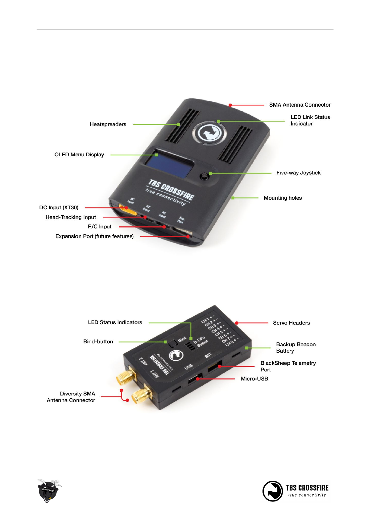
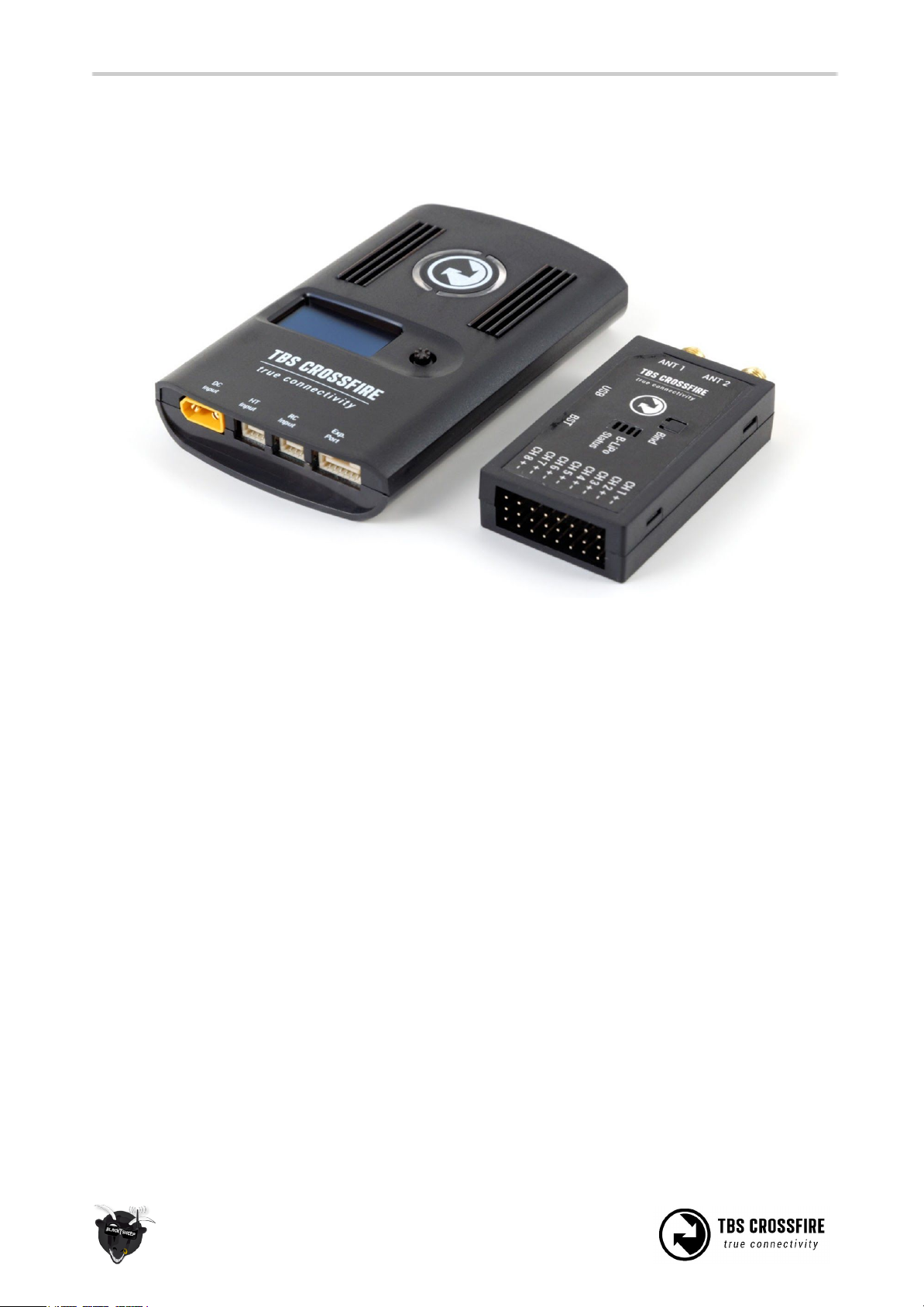
Overview
The following diagram indicates the essential inputs and features of the transmitter and receiver.
Standard transmitter module:
Diversity receiver unit:
7

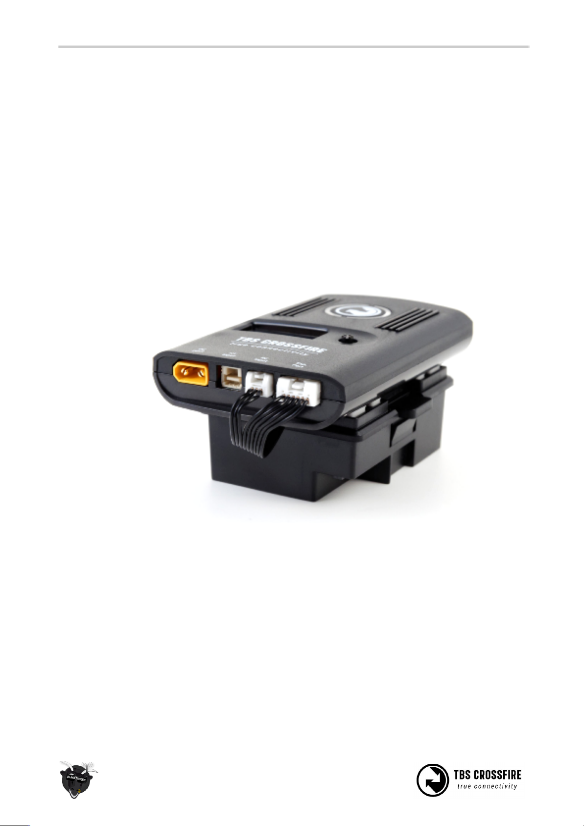
Micro transmitter module:
Micro receiver unit:
Nano receiver unit:
8
Setup
Getting set up and ready to fly is a quick and simple task. In most cases plug&play when using common
R/C equipment.
Connecting CROSSFIRE Standard Transmitter to radio
Using JR-adapter
The kit comes with a JR-adapter which simply works as a connection bridge between the JR-pins on the
radio and the TBS CROSSFIRE transmitter. The adapter simply fits into the slot on the back of the radio. The
radio battery power to the TBS CROSSFIRE and no additional power is necessary for RF output up to
500mW. As of firmware V2.40, ability to unlock 2W RF power when powered from RC- or HT-port (at own
risk).
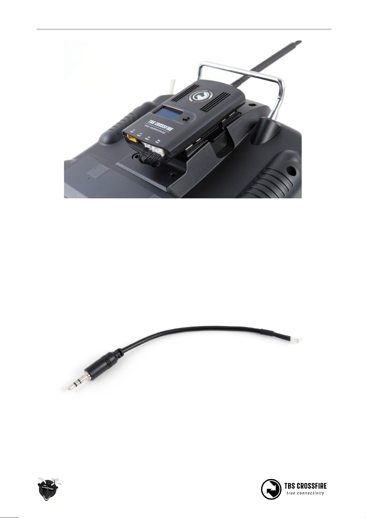
Insert the JR-adapter into the slot on the back of the radio, remove the adhesive sheet from the TBS
CROSSFIRE back and align the four studs with the matching holes on the transmitter. Connect the 3-pin to
the left port (RC) and 6-pin cable (expansion) to the right port on the transmitter.
9
Power on the radio, configure a new model profile and enable the external RF module - see the radio
manufacturers manual for further details on how to complete this step.
Using Hitec/Graupner/JR-cable
If you own a Hitec, Graupner or JR radio (does not work for Spektrum radios) without a JR-module slot, you
can still use the trainer output connector to get the necessary power and PPM control signals to the TBS
CROSSFIRE transmitter. Note that this will not provide CRSF-data, see the following section.
Connect the included cable to the radio trainer port and the other end to the left port (RC) on the
transmitter.
10
This manual suits for next models
3
Table of contents


