TCF IM-5500 Instruction manual
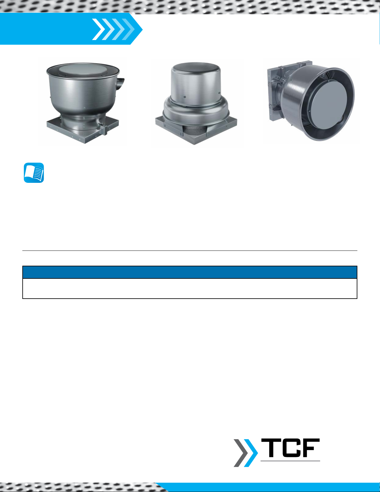
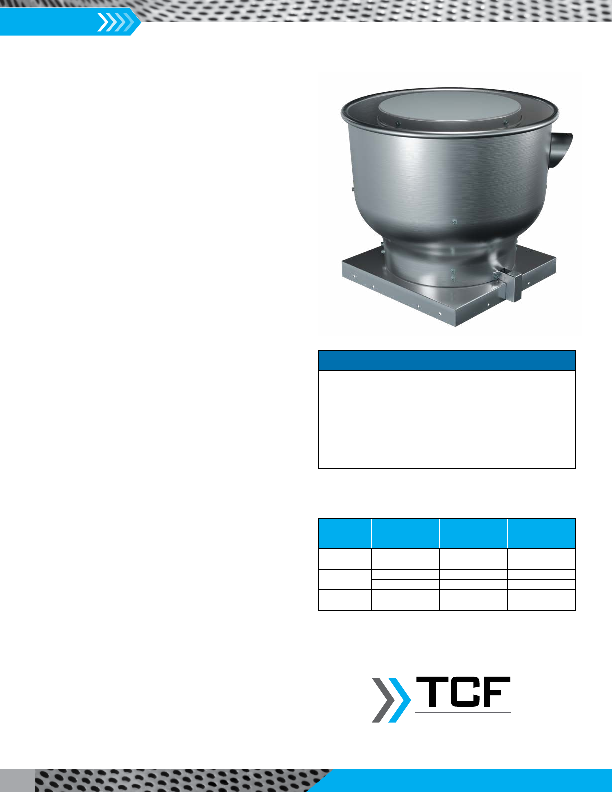
Centrifugal Powered
Roof & Wall Exhausters
IM-5500
August 2023
Installation, Operation & Maintenance Manual
This manual has been prepared to guide the users of centrifugal powered roof and wall exhausters in the proper installation, operation
and maintenance procedures to ensure maximum equipment life with trouble-free operation. For safe installation, startup and
operational life of this equipment, it is important that all involved with the equipment be well versed in proper fan safety practices
and read this manual. It is the user’s responsibility to make sure that all requirements of good safety practices and any applicable
safety codes are strictly adhered to. Because of the wide variety of equipment covered in this manual, the instructions given here are
general in nature. Additional product and engineering information is available at www.tcf.com.
REVIEW AMCA BULLETIN 410 PRIOR TO INSTALLATION
Table of Contents
Exploded View..............................................................................2
Fan Overview
Impeller Rotation and Airflow ..........................................3
Fan Nameplate..................................................................3
Dimensional Data..............................................................3
Receiving, Inspection & Unpacking .............................................4
Safety & Hazard Warnings ...........................................................4
Handling .......................................................................................5
Unit Storage .................................................................................6
General Installation......................................................................7
Check, Test & Start Procedure .....................................................8
Motor Wiring & Installation.........................................................9
Electrical Information...................................................................9
EC Motor Information................................................................10
Fan Bearing Maintenance ..........................................................10
Safety & Bearing Lubrication Instructions .................................10
Speed Control Installation..........................................................11
V-Belts ........................................................................................12
Maintenance ..............................................................................13
Accessory Installation Instructions ...................................... 14-19
Troubleshooting Guidelines .......................................................20
Installation / Start-Up Checklist .................................................21
Fan Maintenance Log........................................................... 22-23
Refer to the Safety section(s) in this manual prior to installing or servicing the fan. The most current version of this installation and maintenance
manual can be found on our website at www.tcf.com/resources/im-manuals.
SAFETY NOTICE
Twin City Fan
IM-5500
Installation, Operation & Maintenance Manual
2
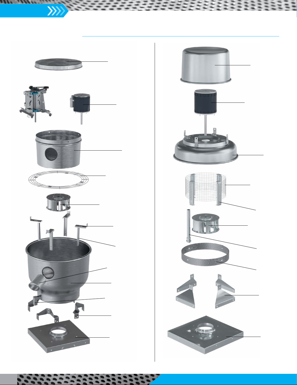
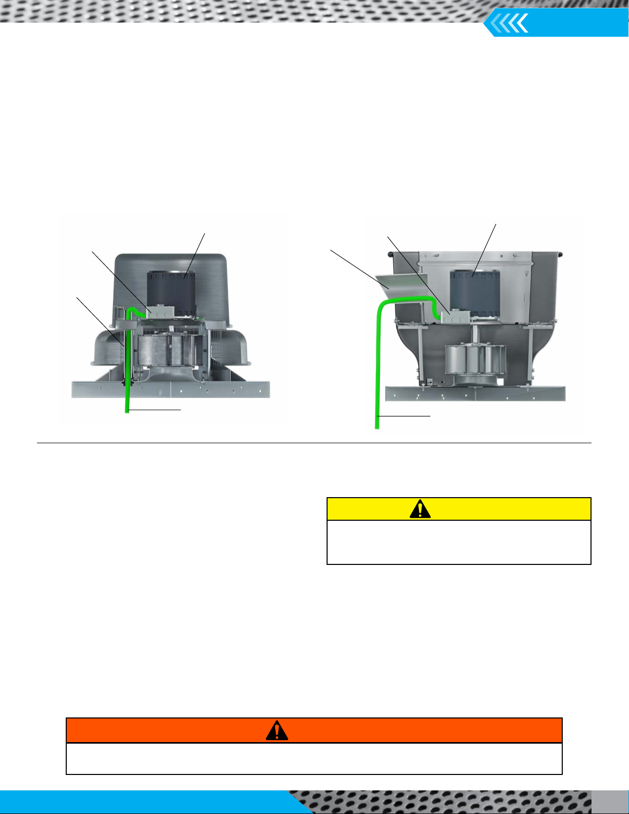
Exploded Views
Motor Cover
Motor
Motor
Housing
Bird Screen
Impeller
Shroud
Curb Cap
Vent Tube
Drain
Support
Brackets
Horizontal
Support
Post
Vertical
Support
Post
Upblast Exhaust Fan,
Models VCU & VCUB
Downblast Exhaust Fan,
Model VC
Motor Cover
Motor
Bird Screen
Impeller
Shroud
Curb Cap
Support
Brackets
Conduit
Vertical
Support
Post
Cutoff

Installation, Operation & Maintenance Manual
IM-5500
3
Blue Arrows = Impeller Rotation
Red Arrows = Airflow
Impeller Rotation and Airflow
Downblast Exhauster
Upblast Exhauster
SIZE CURB CAP DAMPER ROOF/WALL
OPENING
WALL OPENING
WITH MOUNTING
BRACKETS
WALL
MOUNTING
BRACKET SQUARE
APPROX. WEIGHT (lbs.) SHAFT
DIAMETER
(VCUB ONLY)
VCU VCUB
85 17.00 10.00 10.50 17.00 16.75 60 N/A N/A
89 – 112 20.00 14.00 14.50 20.00 19.75 65 N/A N/A
122 – 135 24.00 18.00 18.50 24.00 23.75 95 135 3/4
140 – 165 24.00 18.00 18.50 24.00 23.75 100 135 3/4
177 – 197 30.00 24.00 24.50 30.00 29.75 135 180 3/4
dimensional data – Models VCU, VCUB (Upblast)
SIZE CURB CAP DAMPER ROOF
OPENING
APPROX.
WEIGHT (lbs.)
77 17.00 10.00 10.50 40
83 17.00 10.00 10.50 36
85 17.00 10.00 10.50 36
89 17.00 10.00 10.50 41
98 17.00 10.00 10.50 41
112 17.00 10.00 10.50 43
120 17.00 10.00 10.50 43
dimensional data – Model VC (Downblast)
Fan Overview
Precisely designed for use in roof and wall exhaust applications, the fans covered in this manual offer a broad range of end-use
applications and should be carefully integrated to provide best use. Upblast direct drive fans are available with nominal impeller sizes
from 8.5” to 19.7” and belt driven with nominal impeller sizes 12.2” to 19.7”. Downblast direct drive fans are available in nominal
impeller sizes from 8.5” to 12.0”. Maximum continuous operating temperature for standard build fans is 122°F, with an option for
upblast units for a UL 762 restaurant-rated build for continuous airstream temperatures up to 300°F. Each fan bears an affixed
manufacturer nameplate with the model number and serial number. See below.
Nameplate
The serial number and fan type can be found on our permanent
nameplate of the fan.
Check to ensure the nameplated voltage matches the line
voltage being supplied to the unit.
Twin City Fan & Blower
Minneapolis, MN www.tcf.com
Twin City Fan
Parts & Service
888-444-4823 |fieldservice@tcf.com |parts@tcf.com
model
ser. #
voltshz
class
tag
hp phase
arr.
size
encl.
09-265399-1-1
VCUB
NOTES:
1. All dimensions are in inches unless otherwise noted.
2. Approximate weights shown above include only the bare fan and motor (heaviest at time of publication), not accessories.
IM-5500
Installation, Operation & Maintenance Manual
4
Safety & Hazard Warnings
For general safety practices for air moving equipment, see AMCA Bulletin 410. Twin City Fan & Blower offers many safety accessories.
These safety devices include (but are not limited to) Firestat, inlet and discharge screens. The use and suitability of safety devices is
the responsibility of the purchaser.
All fans should be powered through switches that are easily accessible to service personnel from the fan. Fan power must have the
ability to be “locked out” by service personnel trained in lockout/tagout procedures per OSHA requirements (29CFR1910.147). When
performing lockout, be aware of factors, such as building pressure and additional fans in the system that can influence unwanted fan
rotation (wind milling). If you have any doubt about your ability to perform a task, seek a person qualified to do that task. Before any
work is done on a fan, ensure that the fan is isolated from the electrical supply using a 'lockout/tagout system.'
Note: A stationary, non-rotating fan does not mean that the fan is isolated from the electrical supply. A non-rotating fan could be
subject to controls or other circuit protection devices that may start the fan without notice.
The following safety precautions should be followed, where applicable:
• Do not attempt to slow a rotating impeller even when it is isolated from the electrical supply. Fan impellers have a high inertia and
injury could result from an attempt to stop it. It is recommended that the impeller is isolated by closing off the inlet or outlet to
prevent wind-driven rotation. If an impeller is chocked to prevent rotation, ensure that the chocks are removed prior to start up.
• Wear appropriate personal protective equipment. This may include protective clothing, eye protection, ear protection, respiratory
equipment, hand and foot protection when installing or servicing the fan.
• Always use caution when entering a fan's air path. High velocity airflow can cause you to lose your balance.
• Motor, bearings and drives can be hot, and similarly if the fan is subject to processes that are hot, the fan housing could be hot.
• Sharp edges – wear protective gloves when handling, installing or servicing a fan.
• Fans can operate at high decibel sound levels. Wear proper ear protection to protect from excessive noise levels.
Throughout this manual, there are a number of HAZARD WARNINGS that must be read and adhered to in order to prevent possible
personal injury and/or damage to equipment. Two signal words "WARNING" and "CAUTION" are used to indicate the severity of a
hazard and are preceded by the safety alert symbol. It is the responsibility of all personnel involved in installation, operation and
maintenance to fully understand the warning and caution procedures by which hazards are to be avoided.
WARNING: Used when serious injury or death MAY result from misuse or failure to follow specific instructions.
CAUTION: Used when minor or moderate injury or product / equipment damage MAY result from misuse or failure to follow
specific instructions.
NOTICE: Indicates information considered important, but not hazard-related.
Receiving, Inspection & Unpacking
When the equipment is received all items should be carefully checked against the bill of lading to be sure all crates and cartons have
been received. Before accepting delivery, carefully inspect each carton or crate for visible shipping damage. If any damage is noticed,
the carrier should make the proper notation on the delivery receipt acknowledging the damage. Make notations of all damage on
all copies of the bill of lading and have all copies countersigned by the delivering carrier. The carrier should also fill out a Carrier
Inspection Report. The factory Traffic Department should then be contacted. File claim for damage with the carrier. Physical damage
to the unit after acceptance is not the responsibility of Twin City Fan Companies, Ltd.
Unpack each carton or crate and verify that all required parts and proper quantities of each item have been received. Refer to
drawings for part descriptions. Report shortages or missing items to your local representative to arrange for replacement parts. Due to
availability of carriers and truck space, it is not possible to guarantee that all items will be shipped together. Verification of shipments
must be limited to only those items on the bill of lading.

Installation, Operation & Maintenance Manual
IM-5500
5
Handling
Handling of all air moving equipment should be conducted by trained personnel and be consistent with safe handling practices. Verify
the lift capacity and operating condition of handling equipment. When using hoisting equipment, only qualified and trained personnel
should operate the equipment.
Units shipped completely assembled may be lifted with slings and spreader bars. (Use well-padded chains, cables or nylon straps,
rated to lift the required weight.) On most units, lifting lugs are designed to protect the fan and fan housing from damage. Never lift a
fan by the inlet or discharge flange, shafting or drives, impeller, motor or motor base, or in any other manner that may bend or distort
parts. Never lift with slings or timbers passed through the fan inlets.
Model VC fans: The fan may be lifted by the lip of the shroud. This can either be done manually
(total fan weight is between 50 – 70 lbs.) or with a minimum four-point hook system. Take
precautions to not cause any damage to the shroud.
Model VCU fans:
All Sizes: Fans may be lifted using hooks around the four (4) horizontal support posts with a
minimum of four lifting straps with spreader bars to ensure that no contact is made with the
motor housing.
Sizes 122 and greater: An alternative method for direct drive units between Sizes 122 and 197 is
to utilize the lifting holes located on the motor support plate within the housing. To lift the unit,
four straps and hooks should be used to lift by all four points.
Model VCUB fans: Two lifting lugs located on the bearing support plate provide easy access lifting
points. There are also four holes located on the drive frame bars from which the fan can be lifted.
Wall Mount Fan: Use two lifting straps around the shroud of the fan. One should be located
around the neck of the shroud and the other near to the shroud lip.
Model VCU
(Motor support plate
features four lifting points)
1. Maintain handling equipment to avoid serious personal injury and do not stand under
the load.
2. If supplied, only use the provided lifting lugs to lift the equipment.
3. Ensure that the lifting equipment is rated for the capacity to be lifted.
CAUTION
Model VC with lifting points
Model VCU
(all sizes method)
Model VCUB
(Bearing support plate features
two points for lifting)

IM-5500
Installation, Operation & Maintenance Manual
6
Unit Storage
If fan installation is to be delayed, store the unit in an environmentally stable and protected area. During storage, the fan should
not be subjected to vibration from external sources or bearing damage may occur. The unit should be reasonably protected from
any accidental impacts. Cover the fan to protect coatings and to prevent any foreign material or moisture from entering the inlet or
discharge. Take care to protect the motor, drives and bearings.
Extended storage requires monthly inspections. Check for corrosion or damage to the unit and for debris within the fan.
Bearings tend to take on moisture if the atmosphere in which they are stored is not at a constant temperature. To avoid corrosion, it is
necessary to keep the bearings full of grease and to rotate them periodically. Even when full of grease, bearings will take on moisture,
so it is necessary to purge the bearings with new grease to expel moisture every thirty days. It is recommended that the bearings be
purged with grease while being rotated by hand. Do not use high pressure greasers as they may ruin the bearing seals. Remove old/
excess grease and regrease the bearing in accordance with the bearing manufacturer's instructions.
The drives and belts should be removed if the fan is to be stored for a prolonged period. The drives should be labeled for service and
stored in a dry place. Belts should be removed, coiled without kinks, placed in a heavy carton and stored in a dry, well-ventilated place.
To prevent belt deterioration storage conditions should not exceed 85°F and 70% humidity. If belts show signs of deterioration, they
should be replaced prior to startup.
Motors should be stored in a clean, dry, vibration-free location. The packaging should be opened up enough to allow air circulation
around the motor. The winding temperature should be kept slightly above that of the surroundings to prevent condensation. This can
be accomplished by energizing the internal heaters, if the motor is so equipped, or by using space heaters. If it is impossible to heat the
windings, the motor should be wrapped tightly with a waterproof material that also encloses several bags of desiccant. Replace the
desiccant regularly to prevent moisture problems. The motor rotor should also be rotated regularly (monthly) to assure the bearing
parts are well greased. Shafts on motors equipped with shaft grounding rings must remain rust free. Failure to do so renders the
grounding feature inoperative. Consult the motor manufacturer for further detail on motor storage and start up after longer periods
of storage.
Twin City Fan

Installation, Operation & Maintenance Manual
IM-5500
7
Sheet metal parts, screws, clips and similar items inherently have sharp edges
and it is necessary that the installer and service personnel exercise caution.
CAUTION
General Installation
The installation of this equipment shall be in accordance with the regulations of authorities having jurisdiction and all applicable codes.
This equipment is to be installed by an experienced installation company and fully trained personnel.
The mechanical installation of the exhaust ventilator consists of making final connections between the unit and building services, duct
connections.
1. Install an appropriate roof curb for the fan size and use. Ensure proper caulking
and flashing are installed for a water-tight seal.
a. Sidewall Mounted Units: A wall mounting bracket is shipped for all fans
meant for sidewall installation. Bolt the wall mount bracket to the wall by
pre-drilling pilot holes and then using eight lag screws to secure the bracket.
2. Any backdraft damper, insect screen or performance baffle should be installed
now. Refer to the Performance Baffle Installation section for details.
3. Perform fan pre-check. See Check, Test & Start Procedure section for a full
checklist.
4. Perform installation of any externally mounted accessories that were shipped
loose with the fan.
5. Remove the fan motor housing cover by removing the four screws. See Motor
Housing Cover Removal images to the right for reference on screw location.
6.
a. Roof Mounted Units: Place the unit onto the roof curb. Secure the fan to the
curb with eight lag screws or other suitable fasteners. Verify that the fan is
oriented to facilitate installation of wiring.
b. Sidewall Mounted Units: Align and then affix the fan onto the wall mounting
bracket using the hardware provided. NOTE: The drain should always be
facing directly down and the vent tube to the lower right corner. See image
below for drain and vent tube location.
c. NOTE: If curb hinge, security latch or retaining chain accessories are selected,
please reference the Curb Hinge, Security Hasp and/or Retaining Chain
installation instructions towards the back of this manual.
7. Follow the Motor Wiring and Installation instructions section. Verify installation
of any accessories that were shipped loose with the unit.
8. Affix the motor housing cover back onto the unit.
Upblast
Motor housing cover removal
Downblast
Twin City Fan
Wall mounted unit with correct drain and vent
tube location
IM-5500
Installation, Operation & Maintenance Manual
8
FAN
TYPE SIZES OVERLAP
(+/- 0.05")
VCU 085 0.20"
VCU 089 0.13"
VCU 098 0.13"
VCU 110 0.13"
VCU 112 0.20"
VCU & VCUB 122 0.20"
VCU & VCUB 124 0.13"
VCU & VCUB 135 0.20"
VCU & VCUB 140 0.13"
VCU & VCUB 150 0.20"
VCU & VCUB 157 0.13"
VCU & VCUB 165 0.20"
VCU & VCUB 177 0.20"
VCU & VCUB 182 0.20"
VCU & VCUB 197 0.20"
VC ALL SIZES 0.13"
Check, Test & Start Procedure
1. General unit check:
a. Check for any defects or damage. Contact your local
representative if any damage is present.
b. Verify that all accessories are installed and operational.
c. Validate all fasteners are secure and there are no loose parts.
2. Impeller check:
a. Validate that the impeller is free and able to rotate.
b. Validate that the impeller to inlet venturi overlap is maintained. See Impeller to Inlet Venturi table below for the specified
overlap.
c. Apply power to the unit and check the rotation of the impeller. The label within the motor housing indicates the direction. See
images in the Impeller Rotation and Airflow section for visual aid.
d. Verify fan RPM using a tachometer. If a speed controller is used, check that the maximum and minimum RPM are as desired. If
the minimum RPM is not as desired, see Speed Control Installation section for instructions on how to adjust.
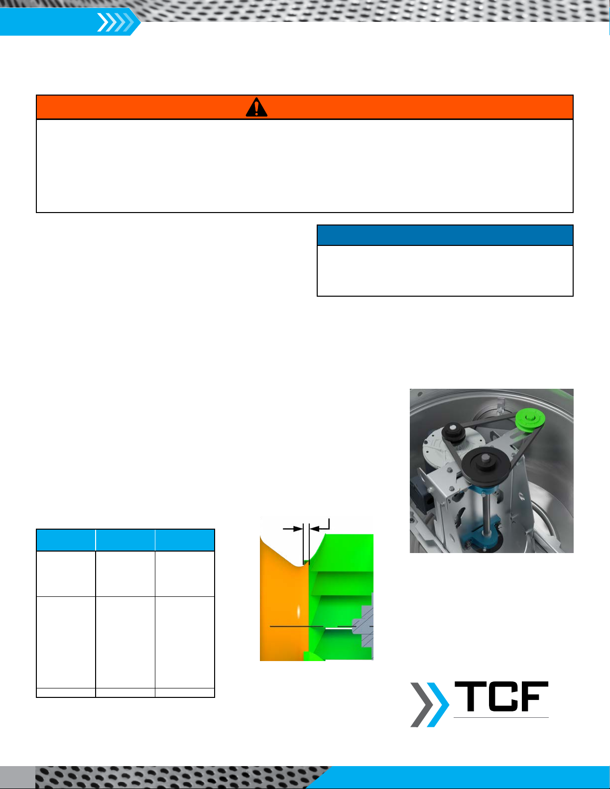
3. Drive and belt check (VCUB fans ONLY):
a. Verify that sheaves and idler pulley (auto-tensioner if accessory was selected) are
aligned parallel.
b. Verify that the belt is taut with minimal deflection. Adjustment can be made by
sliding the idler pulley along the groove to either tighten or loosen the belt. See
image to the right.
c. Verify the RPM of the impeller. Adjustment can be made via the variable speed
sheave attached to the motor to reach the desired RPM.
d. Bearings should be properly greased from the manufacturer.
e. See the V-Belts section for further information.
1. Electric shock hazard. Could cause severe injury or death. Failure to bond the frame of this equipment to the building electrical ground
by use of the grounding terminal provided or other acceptable means may result in electrical shock. Disconnect electric power before
servicing equipment. Service to be performed only by qualified personnel. Make sure power is turned off and locked in the OFF position.
2. Impeller rotation is critical. All units are designed to rotate in a CCW direction. If spun in the opposing direction, fan performance is heavily degraded
and the motor will overload and burn out prematurely.
3. Three-phase units are especially susceptible to incorrect rotation due to the ease of incorrectly connecting the wires. If the unit is checked on
temporary wiring, impeller rotation should be rechecked when permanently installed. Motor burn out or tripped overload protection devices
are key indications of a fan left to run in the wrong rotation.
WARNING
Impeller to Inlet Venturi
The impeller was balanced at the factory to be within stringent
vibration levels before shipment. However, there are several
things that may cause vibration, such as rough handling in
shipment and installation, weak foundations and alignments.
NOTICE
Model VCUB Idler Pulley
Impeller Overlap
Twin City Fan
Overlap
Installation, Operation & Maintenance Manual
IM-5500
9
Motor Wiring & Installation
1. Proper Lockout/Tagout procedures should always be followed as discussed in the Safety & Hazard Warnings section. Verify that no
power is on the circuit to which the fan is being connected.
2. Run appropriately rated wiring for the installation method to the junction box located within the motor housing; only ½”
knockouts available.
Downblast Fans: The electrical supply is routed through conduit between the curb cap and motor compartment.
Upblast Fans: The electrical supply is routed through the vent tube.
See images below for electrical routing.
a. Refer to the accessory installation portion towards the end of this manual for additional wiring instructions for various wired
accessories.
3. Leave enough slack in the wiring for maintenance accessibility.
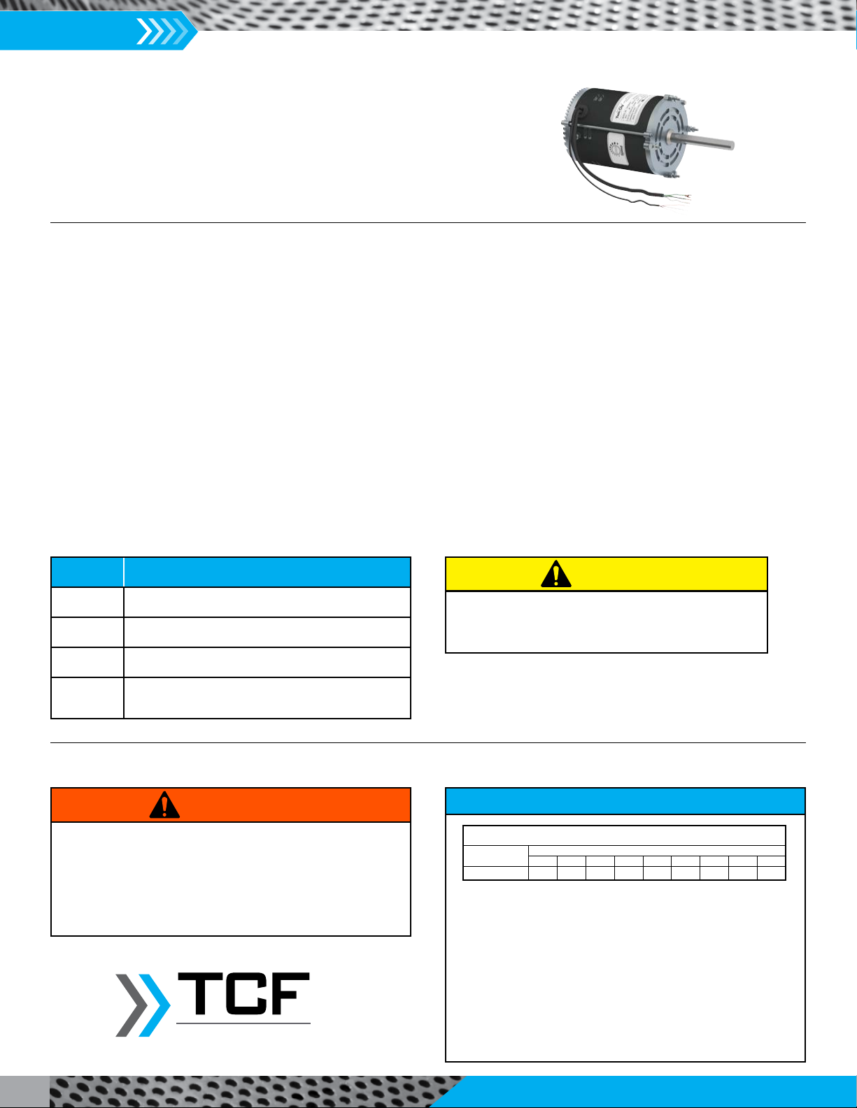
Electrical Information
1. Check the wiring diagrams on the motor for connections.
2. The motor is factory set at the voltage marked on the fan
nameplate. Check the line voltage with the nameplate voltage
and wiring diagrams.
3. The main power wiring should be sized for the ampacity shown
on the dataplate. Size wires in accordance with the ampacity
tables in Article 310 of the National Electrical Code. If long wires
are required, it may be necessary to increase wire size to prevent excessive voltage drop. Wires should be sized for a maximum of
3% voltage drop.
4. Disconnect switches are not fused. The power leads must be protected at the point of distribution in accordance with the fan
dataplate.
5. On fans without a thermal protector integral to the motor (refer to unit or motor dataplate to determine if protector is present) a
separate overload device is required. Refer to Sections 430-32 of the N.E.C. for sizing.
6. All units must be electrically grounded in accordance with local codes or, in the absence of local codes, with the latest edition of the
National Electrical Code (ANSI/NFPA 70). A ground lug is provided as standard in the unit terminal box. Size grounding conductor
in accordance with Table 250-95 of the National Electrical Code. DO NOT use the ground lug for connecting a neutral conductor.
7. Supply voltage to the power ventilator should not vary by more than 10% of the value indicated on the unit dataplate. Phase
unbalance must not exceed 2%.
Failure of motor due to operation on improper line voltage or with excessive phase unbalance constitutes product abuse and
may cause severe damage to the unit’s electrical components.
WARNING
1. Use copper conductors only.
2. Protect wiring from sharp edges. Leave some slack in the line
to prevent damage.
CAUTION
Motor
Junction
Box
Conduit
Field
Wiring
Motor
Junction
Box
Field
Wiring
Vent
Tube
IM-5500
Installation, Operation & Maintenance Manual
10
*Suggested lubrication interval under continuous operation in adverse loading or with
elevated temperatures. For operation less than 24 hours per day or under ideal conditions,
lubrication frequency may be reduced. Relubricate while running, if safety permits, until
some purging occurs at seals. Adjust lubrication frequency depending on condition of
purged grease. Hours of operation, temperature and surrounding conditions will affect the
relubrication frequency required.
1. Lubricate with a high quality NLGI No. 2 lithium-base grease having rust inhibitors and
antioxidant additives, and a minimum oil viscosity of 500 SUS at 100°F (38°C). Some
greases having these properties are:
Shell - Gadus S2 V100 2 Mobil - Ronex MP
Mobil - Mobilith SHC100 Mobil - Mobilith SHC220
2. Lubricate bearings prior to extended shutdown or storage and rotate shaft monthly to aid
corrosion protection.
Fans with Ball Bearings
Relubrication Schedule (Weeks)*
Ball Bearing Pillow Blocks
Shaft DIA Speed (RPM)
500 1000 1500 2000 2500 3000 3500 4000 4500
3⁄4" (19 mm) 665332221
1. This equipment must not be operated without proper guarding
of all moving parts. While performing maintenance be sure
remote power switches are locked off. See installation manual
for recommended safety practices.
2. Before starting: Check all set screws for tightness and rotate
impeller by hand to make sure it has not moved in transit.
WARNING
Safety & Bearing Lubrication Instructions
Twin City Fan
Fan Bearing Maintenance (refer to safety section)
Proper lubrication of the fan drive bearings helps assure maximum bearing life. All fans are equipped with decals indicating the
recommended relubrication intervals for normal operating conditions.
The standard pillow block bearings on belt driven ventilators are factory lubricated and are provided with external grease fittings.
Annual lubrication is recommended, or more frequently if needed (see Greasing Intervals table). It is recommended to add fresh grease
at start-up, but do not over-grease. Use only 1 or 2 shots of a recommended lubricant with a hand gun in most cases. Maximum hand
gun rating 40 P.S.I. Rotate bearings during lubrication where good safety practice permits. The most frequent causes of bearing failure
are not greasing often enough, using an excessive quantity of grease or using incompatible greases. Excessive vibration, especially if
the bearing is not rotating, will also cause bearings to fail. Bearings must also be protected from water and moisture to avoid internal
corrosion.
During the rst few months of operaon it is recommended that the bearing set screws be checked periodically to ensure that they are
ght. The rotang impeller requires parcular aenon since materials in the air being handled can build up on the blades to cause
destrucve vibraon or weaken the structure of the impeller by corroding and/or eroding the blade metal. Regular inspecon and
correcve acon at intervals determined by the severity of each applicaon are essenal to good service life and safety.
Suggested Fan Bearing Greasing Intervals
INTERVAL
(MONTHS) TYPE OF SERVICE
12 to 18 Infrequent operaon or light duty in clean atmosphere
6 to 12 8 to 16 hrs./day in clean, relavely dry atmosphere
3 to 6 12 to 24 hrs./day, heavy-duty or if moisture is present
1 to 3 Heavy-duty in dirty, dusty locaons; high ambient
temperatures; moisture-laden atmosphere; vibraon
Greases of different soap bases (lithium, sodium, etc.) may
not be compatible when mixed. Prevent such intermixing
by completely purging the bearing of old greases.
CAUTION
EC Motor Information
See IM-4055 for EC motor details.
Installation, Operation & Maintenance Manual
IM-5500
11
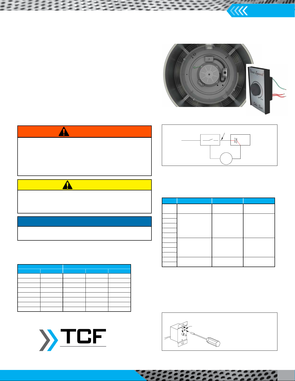
Low End Setpoint Adjustment
NOTE: 5 amp model shown.
On 10 and 15 amp models,
adjustment is made through
clearance hole in heat sink. The
faceplate must be removed on
the 5 amp model to access this
screw.
SETPOINT
ADJUSTMENT
SCREW
Speed Controller Size
Speed Controller RPM Range
NOTES:
1. Speed control available only with 115/60/1 open motors (thermally protected).
2. Three-speed motor (multiple tap winding).
3. Speed control should not be connected to low speed tap on motor because of
starting characteristics.
4. Speed control connected to high speed tap on motor.
5. Speed control connected to medium speed tap on motor.
MOTOR SPEED CONTROLLER (FLA)
HP RPM 5 AMP 10 AMP 15 AMP
1/30 ALL X
1/15 ALL X
1/8 ALL X
1/6 ALL X
1/4 ALL X
1/3 <= 1500 X
1/3 > 1500 X
1/2 ALL X
HP RPM MAX. RPM MIN. RPM
1/30 1650/1500/13502,3 1650413004
1/8 150059505
1/15
860 860 500
1/8
1/6
1/4
1/2
1/8
1140 1140 900
1/6
1/4
1/2
1/3 1725 1725 1200
1/2
Speed Control Installation
When the controller is shipped loose, it can be installed externally, or
alternatively it can be installed inside of the fan 90 degrees from the
disconnect switch. On Model VCU it can be installed between the rib
and the raised motor mounting section of the housing compartment.
Speed control is available using 115/60/1 open type PSC motors.
Connect control in series with motor and line voltage (115V only).
Never connect across line. See Connection Diagrams.
Minimum Speed Setpoint
All controls are factory set to 65V±3V output as standard with an
input voltage of 120V. If different minimum speed is desired, the
control may be adjusted by turning minimum speed pot clockwise
to decrease minimum speed and counterclockwise to increase
minimum speed. Refer to Low End Setpoint Adjustment figure. Connection Diagrams, Speed Control
SPEED CONTROLLER WITH A NEMA 1 POWER SWITCH
Incoming Power Leads
NEMA 1 Switch
Motor Power Leads
Motor
Motor Control Leads
TRI-AC
Wire Harness
1. If minimum speed is readjusted, verify unit ampere draw does not
exceed motor nameplate amps. Do not operate unit in range where
amp draw exceeds motor nameplate.
2. Certain failure modes of solid-state controls such as half-waving can
cause high levels of DC, motor overheating and motor burn-out.
Therefore, a thermal overload protection (integral with motor) is
required to limit the maximum motor temperature under such a failure.
WARNING
These motors operate more efficiently in the ranges set from the
factory. Operating motor outside these ranges (see Speed Controller
RPM Range table) may cause the motor to run hotter and substantially
shorten motor life.
CAUTION
1. Lowering the minimum speed setpoint may adversely affect motor
start-up characteristics.
NOTICE
One red wire will be connected to the AC line voltage. The second red wire
will be connected to the input power lead for the motor. The green wire
is the ground wire.
Typical Speed Control Installation Location
Twin City Fan
IM-5500
Installation, Operation & Maintenance Manual
12
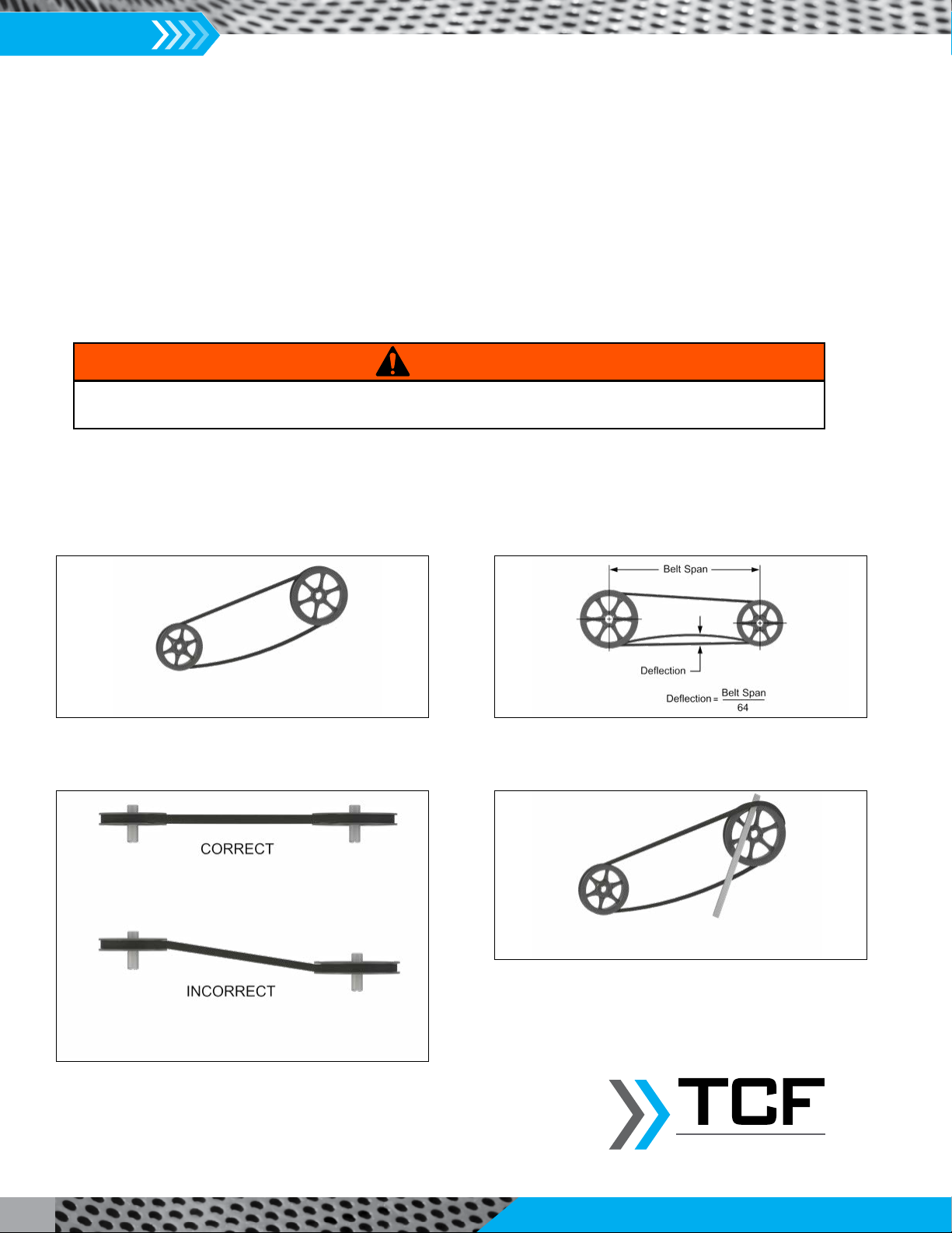
Figure 1. Eliminate Slack Figure 2. Belt Deflection
Figure 3. Alignment Figure 4. Belts
Slack belts wear excessively, cause slippage and deliver less power.
For longest belt life, always provide proper tension.
Mount belts straight. Shafts must be parallel and sheaves in
alignment to prevent unnecessary belt wear.
Do not force belt. Forcing the belt will break the cords and
cause belt failure.
V-Belts (refer to safety section)
V-belts on these belt driven fans are oil, heat and static resistant type and oversized for continuous-duty. With proper installation and
maintenance, years of operating efficiency can be added to the lifespan of the V-belt drive.
The condition of V-belts and the amount of belt tension should be checked prior to start-up (see Figure 1). When it becomes necessary
to adjust belt tension, do not over-tension as bearing damage will occur. Recommended belt tension should permit 1/64" deflection per
inch of span of the belt at the center of the belt span. To find this point, measure halfway between the pulley centerlines as shown in
Figure 2. Extreme care must be exercised when adjusting V-belts as not to misalign the pulleys. Any misalignment will cause a sharp
reduction in belt life and will also produce squeaky, annoying noises (see Figure 3).
1. Always loosen tension adjustment enough to place belts on sheaves without running belts over the edge of either sheave. A new
belt may be seriously damaged internally by careless handling (see Figure 4).
2. Fan speed can be increased by closing the adjustable motor pulley or decreased by opening it. Always check the load on the motor
when increasing the fan speed.
When removing or installing belts, never force belts over pulleys without loosening the idler pulley or auto belt tensioner first to
relieve belt tension.
WARNING
Twin City Fan

Installation, Operation & Maintenance Manual
IM-5500
13
Maintenance (refer to safety section)
Installation and maintenance are to be performed only by
qualified personnel who are familiar with local codes and
regulations and experienced with this type of equipment.
Preventive maintenance is the best way to avoid unnecessary
expense and inconvenience. Start-up and routine maintenance
should cover the following items:
a. Tighten all set screws, bolts and wire connections.
b. Cleaning of unit, impeller and damper (if present).
All motors containing ball bearings are permanently
lubricated from the factory. No additional maintenance is
required.
1. Before performing any maintenance on the fan, be sure power is turned off and locked in the OFF position at the service entrance.
2. Ventilators should be carefully checked at least once a year. For critical or rugged applications, a routine check every two or three
months is suggested.
3. All motors supplied with Twin City Fan & Blower ventilators carry a one-year limited warranty from date of shipment. For repairs
within the warranty period, the motor must be taken to the motor manufacturer’s authorized service dealer. Contact your
representative for additional warranty details.
4. A periodic motor check should consist of spinning the motor shaft with the power off to be sure the motor turns freely and the
bearings run smoothly.
5. The rotating impeller requires particular attention since materials in the air being handled can build up on the blades to cause
destructive vibration or weaken the structure of the impeller by corroding and/or eroding the blade metal. Regular inspection and
corrective action at intervals determined by the severity of each application are essential to good service life and safety.
Sharp edges and screws are a potential injury hazard. Avoid them.
CAUTION
Hazardous moving parts. Unit may contain protected fan motor
that may start automatically and cause injury. Allow time for
reset. Disconnect power before servicing.
WARNING
Twin City Fan
IM-5500
Installation, Operation & Maintenance Manual
14
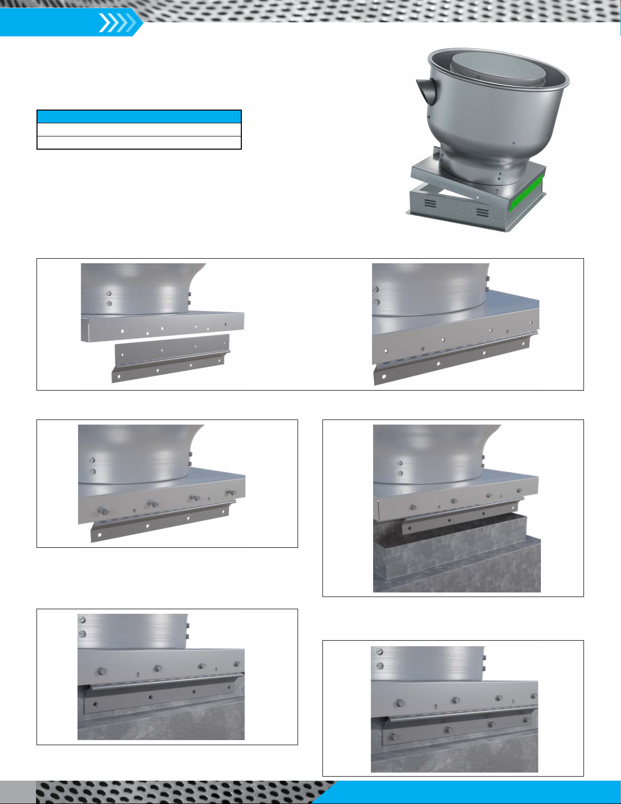
Curb Hinge Installation
Parts Included
Curb Hinge
1/4-20 x 0.50" Lg Self-Tap Screw (Qty 8, 10 or 12)
Step 1: Align the holes on the curb hinge to the holes on the curb cap. This should be on the opposite side of the drain.
A. B.
Step 2: Insert provided screws to affix the hinge to the curb cap. Step 3: Place and install fan onto the roof curb.
Step 4: Properly align the fan with the roof curb. Pre-drill
holes for securing hardware.
Step 5: Fasten hinge to roof curb with customer provided
hardware.
Installation, Operation & Maintenance Manual
IM-5500
15
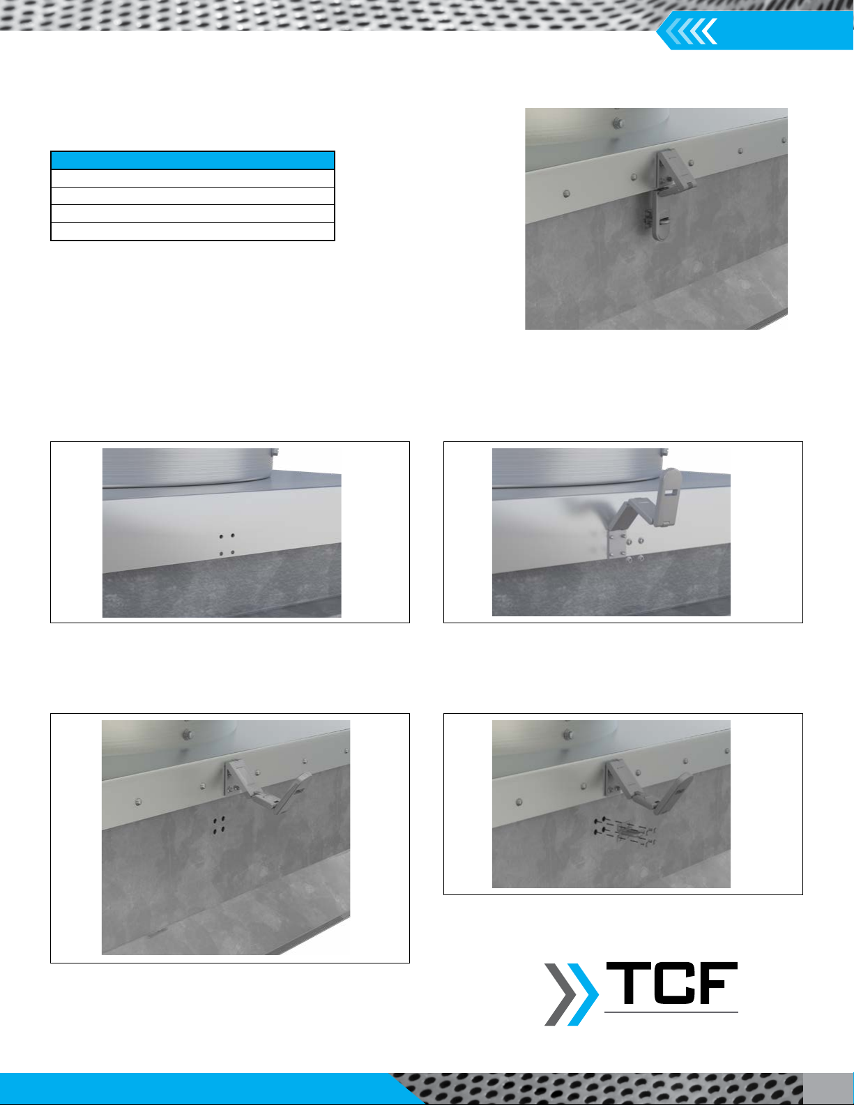
Security Hasp Installation
Parts Included
10-32 x 3/4", Bolt, Hex (4)
#10 , Star Washer (4)
#10 , Nut Hex (4)
Security Hasp, Hinged
Step 1: Drill (4) 0.19 holes on center curb cap from either
corner.
Step 2: Attach the hasp to the curb cap by using the included
#10 hardware.
Step 3: Drill (4) 0.19 holes on center of roof curb, 2" from
curb cap edge to top edge of staple. Step 4: Fasten staple with screws on roof curb.
Twin City Fan
Properly mated security hasp

IM-5500
Installation, Operation & Maintenance Manual
16
Retaining Chain Installation
Step 1: Drill two 1/4" diameter holes, one each corner of
curb base.
Step 2: Attach chain to outside of curb base with bolt head
on inside of curb base.
Step 3: Use one flat washer under bolt head and one on top
of chain.
Step 4: Use remaining fasteners to attach other end of chain
to anchor point.
Twin City Fan
Parts Included
Chain, 42" (2)
1/4-20 x 3/4" Bolt (4)
1/4-20 Nylon Hex Nut (4)
1/2" Washer (8)
Installation, Operation & Maintenance Manual
IM-5500
17
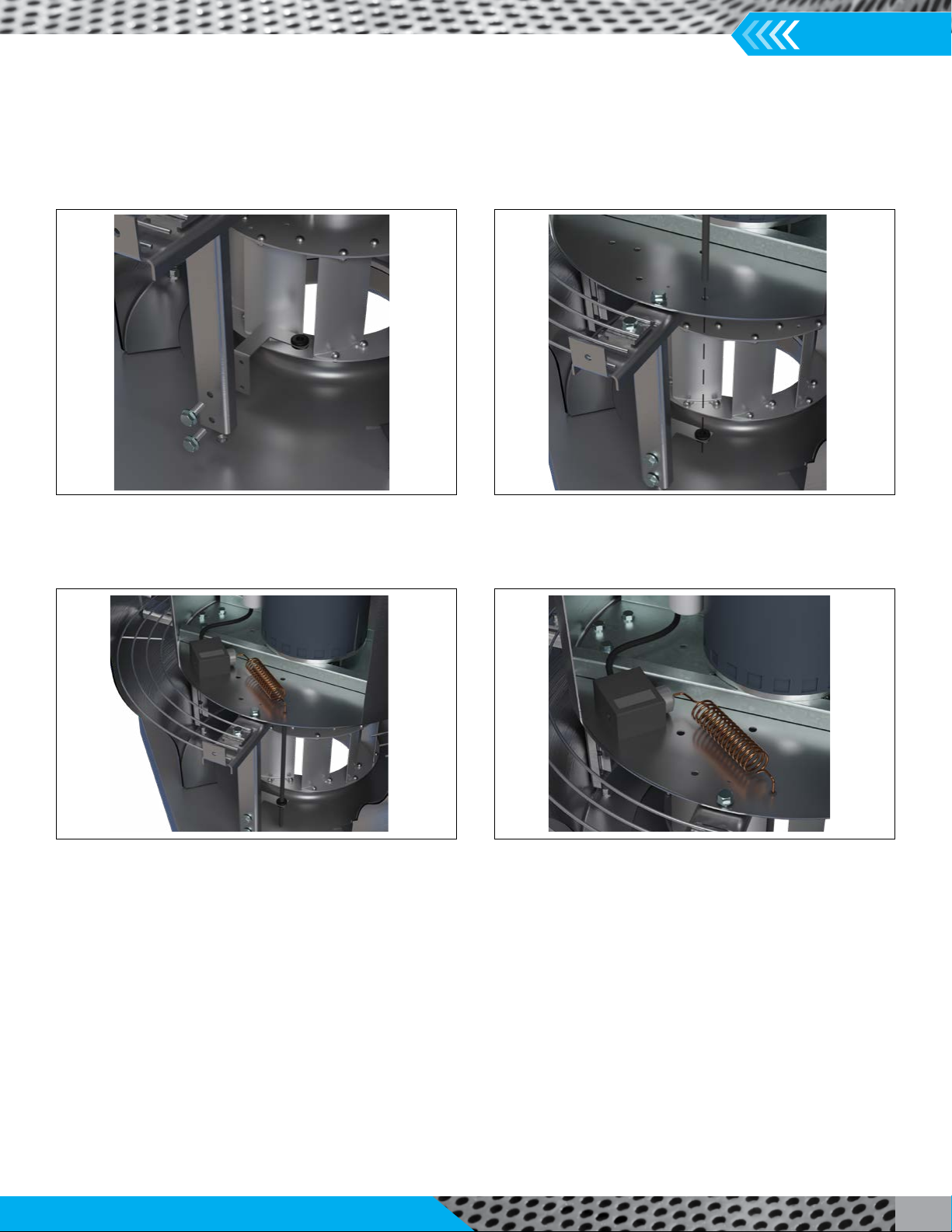
Firestat Installation
Step 1: Attach the bracket provided to the motor housing
support using the self-tapping screws that are fastened to the
support post.
Step 2: Drill holes and install firestat. Holes must be near a
support post. Note: The hole drilled in the motor housing must
be close to in line with the hole in the bracket provided.
Step 3: Cable tie sensing bulb to the nearest vertical support
post.
Step 4: Wire the firestat to the disconnect switch and motor.
IM-5500
Installation, Operation & Maintenance Manual
18
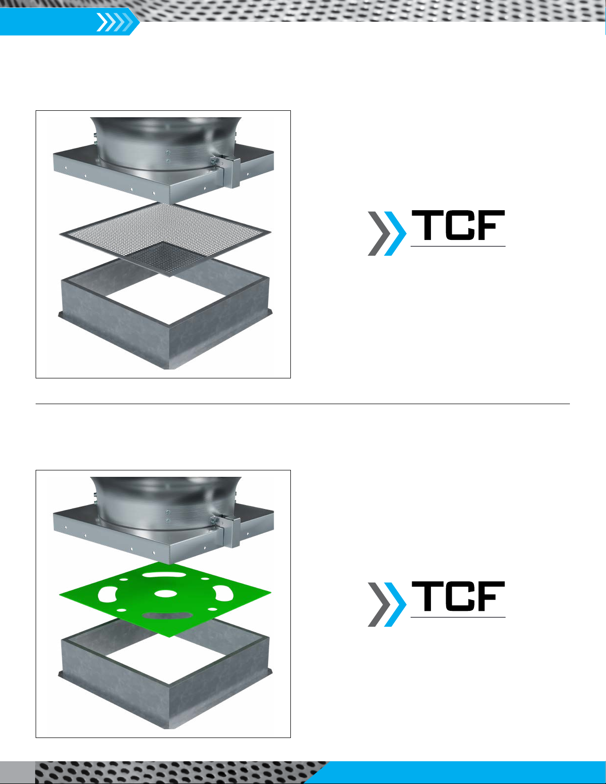
Insect Screen Installation
Step 1: Place the insect screen between the fan inlet and the roof or roof curb. Fasten with screws or nails, if desired.
Twin City Fan
Performance Baffle Installation
Step 1: Place the performance baffle between the fan inlet and the roof or roof curb. Fasten with screws or nails, if desired.
Twin City Fan

Installation, Operation & Maintenance Manual
IM-5500
19
Damper Installation
Step 1: Attach using sheet metal screws. (Roof curbs come with damper trays.)
Grease Box Installation
Step 1: Fasten the grease box to the curb cap under the drain, using supplied hardware.
Parts Included
Grease Box
Cover
Grease Pad
1/4-20 x 5/8" Lg Hex Bolt
1/4-20 Hex Nut
Washer, Flat, 1/4"
Twin City Fan
Twin City Fan
IM-5500
Installation, Operation & Maintenance Manual
20
Troubleshooting Guidelines
Use current safety practices when investigating fan or system
performance problems. General safe practices and performance
troubleshooting guidelines can be found in AMCA Publications
410 and 202, respectively. Fan application and field measurement
procedures can be found in AMCA Publications 201 and 203.
Below is a list of possible areas to check when air or sound values
do not match expectations. Most fan problems can be pinpointed
to one of these common causes.
Air Capacity Problems
1. Resistance of the system is not at design rating. If resistance is
lower than expected, both airflow and horsepower may be up.
If resistance is higher than anticipated, air volume will be down.
2. Fan speed is not at design speed.
3. Air density is not at the design value. Also check air performance
measurement techniques/procedures.
4. Devices for air modulation are closed or plugged. Also check
filters.
5. Impeller mounted improperly or is rotating in reverse.
6. Parts of the system or fan have been damaged or need cleaning.
Noise Problems
1. Air performance is incorrect and the fan is not at design point
of operation. Fan is being forced to operate in an unstable flow
region near peak or to the left of the peak of the curve.
2. Supply voltage high or inconsistent supply frequency. Adjustable
frequency controllers can generate motor noise.
3. Objects, including flow sensors, that are installed in a high
velocity airstream can generate noise.
4. Poor fan inlet conditions.
5. Acoustics or sound measurement procedure incorrect.
Vibration Problems
1. Poor foundation or mounting structure (resonances).
2. Foreign material attached to rotating components.
3. Damaged rotating components (bearings, shaft, fan, impeller,
sheaves).
4. Broken, loose or missing set screws.
5. Loose hardware.
6. Vibration transmitted by another source.
7. Fan is operating in stall or unstable flow region.
Motor Problems
1. Incorrect wiring.
2. Speed of fan too high.
3. Parts improperly installed; binding.
4. WR2capability of motor too low for application.
5. Protection devices may be improperly sized.
6. VFD compatible electrically? Effective shaft grounding?
7. Is cabling and grounding correct?
Vibration Guidelines
Condition
Fan
Applicaon
Category
Rigidly Mounted
mm/s (in./s)
Flexibly Mounted
mm/s (in./s)
Start-up
BV-3 6.4 (0.25) 8.8 (0.35)
BV-4 4.1 (0.16) 6.4 (0.25)
Alarm
BV-3 10.2 (0.40) 16.5 (0.65)
BV-4 6.4 (0.25) 10.2 (0.40)
Shutdown
BV-3 12.7 (0.50) 17.8 (0.70)
BV-4 10.2 (0.40) 15.2 (0.60)
Values shown are peak velocity, mm/s (inches/s), Filter out. Table taken from ANSI/AMCA
Standard 204-05, Table 6.3. AMCA defines BV-3 for applications up to 400 HP; BV-4 for
applications over 400 HP.
All fans manufactured by Twin City Fan & Blower are factory
balanced prior to shipment. Installation variables, handling and
movement of the fan during shipment may cause the rotating
assembly to shift. Balance should be checked once the fan is
installed. If a final trim balance is required, it is the end user's
responsibility to bring the fan back to factory specifications. Final
trim balancing is not the responsibility of Twin City Fan & Blower.
Refer to the Vibration Guidelines table below.
NOTICE
Twin City Fan
Table of contents
Popular Ventilation Hood manuals by other brands

Pkm
Pkm S7-60 ABTH instruction manual

NuTone
NuTone Elite EW4830SS Installation use and care manual

Hanseatic
Hanseatic SY-103A6-P1-C59-600 user manual

hestan
hestan KVI Installation use and care manual

KOBE
KOBE RA2230SQF Installation instructions and operation manual

ROBINHOOD
ROBINHOOD RHCV9G VETRO WALL installation instructions


