TCi MotorShield MSD0009A300 User manual

High Performance Output
Sine Wave Filter
Installation, Operation, and Maintenance Manual
TCI, LLC
W132 N10611 Grant Drive
Germantown, WI 53022
Phone: 414-357-4480
Fax: 414-357-4484
Helpline: 800-TCI-8282
www.transcoil.com
©2019 TCI, LLC All right reserved
Product No: 29343
Effective 10/15/19 Version F


Table of Contents
1.0 Safety .........................................................................................................................1
Safety Instructions Overview .................................................................................................................1
Warnings and Cautions .........................................................................................................................1
Warnings............................................................................................................................................... 1
Cautions................................................................................................................................................ 1
General Safety Instructions ...................................................................................................................2
2.0 General Information ..................................................................................................3
Intended Audience.................................................................................................................................3
Installation Checklist..............................................................................................................................3
Receiving Inspection .............................................................................................................................3
TCI Limited Warranty Policy ..................................................................................................................4
Storage Instructions...............................................................................................................................4
Product Description ...............................................................................................................................5
Filter Configuration ................................................................................................................................6
Nameplate Data.....................................................................................................................................8
Part Number Encoding ..........................................................................................................................9
Standard Product Ratings and Dimension Tables ................................................................................9
Product Technical Specifications ........................................................................................................11
3.0 Pre-installation Planning ........................................................................................12
Verify the Application...........................................................................................................................12
Variable Frequency Drive Settings ..................................................................................................... 12
Environment........................................................................................................................................ 12
Working Space ....................................................................................................................................12
Power Wiring .......................................................................................................................................12
Thermal Switch ....................................................................................................................................13
Optional Features ................................................................................................................................13
4.0 Installation Guidelines............................................................................................14
Wiring...................................................................................................................................................14
Before Connecting ...............................................................................................................................14
Over Temperature Switch....................................................................................................................14
Field Wiring Connection Terminals .....................................................................................................14
Connection Diagram ............................................................................................................................16
Grounding ............................................................................................................................................16
Power Wiring .......................................................................................................................................16
5.0 Operation .................................................................................................................17
Variable Frequency Drive Settings ..................................................................................................... 17
Start Up (Commissioning) ...................................................................................................................17
Before Applying Power for the First Time............................................................................................17
Before Operating the VFD for the First Time.......................................................................................17
6.0 Maintenance and Service .......................................................................................18
Reliability and Service Life ..................................................................................................................18
Periodic Maintenance ..........................................................................................................................18
Reactor and Capacitor Temperature Switches ...................................................................................19
Evaluating MotorShield™Performance ...............................................................................................19
Replacement Parts ..............................................................................................................................20
Factory Contacts and Tech Support....................................................................................................20

Revision
Description
Date
A
Release
5/14/15
B
Updates to Section 4
5/29/15
C Add UL information
Added 362A, 420A, 480A
Updated wire size / torques
8/19/15
D Updates to drawings in Section 6 6/16/17
E Updates to Product Ratings and Dimensions Table
Updates to Installation Checklist
9/18/17
F Revision of technical specifications and overall reformat 1015/19
We strive to provide the most up to date and accurate documentation available at the time of
printing. Please visit www.transcoil.com for the most recent revision of this manual.

MSD Manual 1.0 Safety
1
1.0 Safety
Safety Instructions Overview
This section provides the safety instructions which must be followed when installing, operating
and servicing the MotorShield™Filter. If neglected, physical injury or death may follow, or damage
may occur to the MotorShield™or equipment connected to the MotorShield™. The material in this
chapter must be read and understood before attempting any work on, or with, the product.
The MotorShield™is intended to be connected to the output terminals of a variable frequency
drive (VFD). An AC motor is connected to the output terminals of the MotorShield™and receives
power from the VFD through the MotorShield™. The instructions, and particularly the safety
instructions, for the VFD, motor and any other related equipment must be read, understood and
followed when working on any of the equipment.
Warnings and Cautions
This manual provides two types of safety instructions.
Warnings caution readers about conditions, which can, if proper steps are not taken, lead to a
serious fault condition, physical injury, or death.
Cautions are used to draw attention to instructions. Failure to properly follow such instructions
may lead to a malfunction and possible equipment damage.
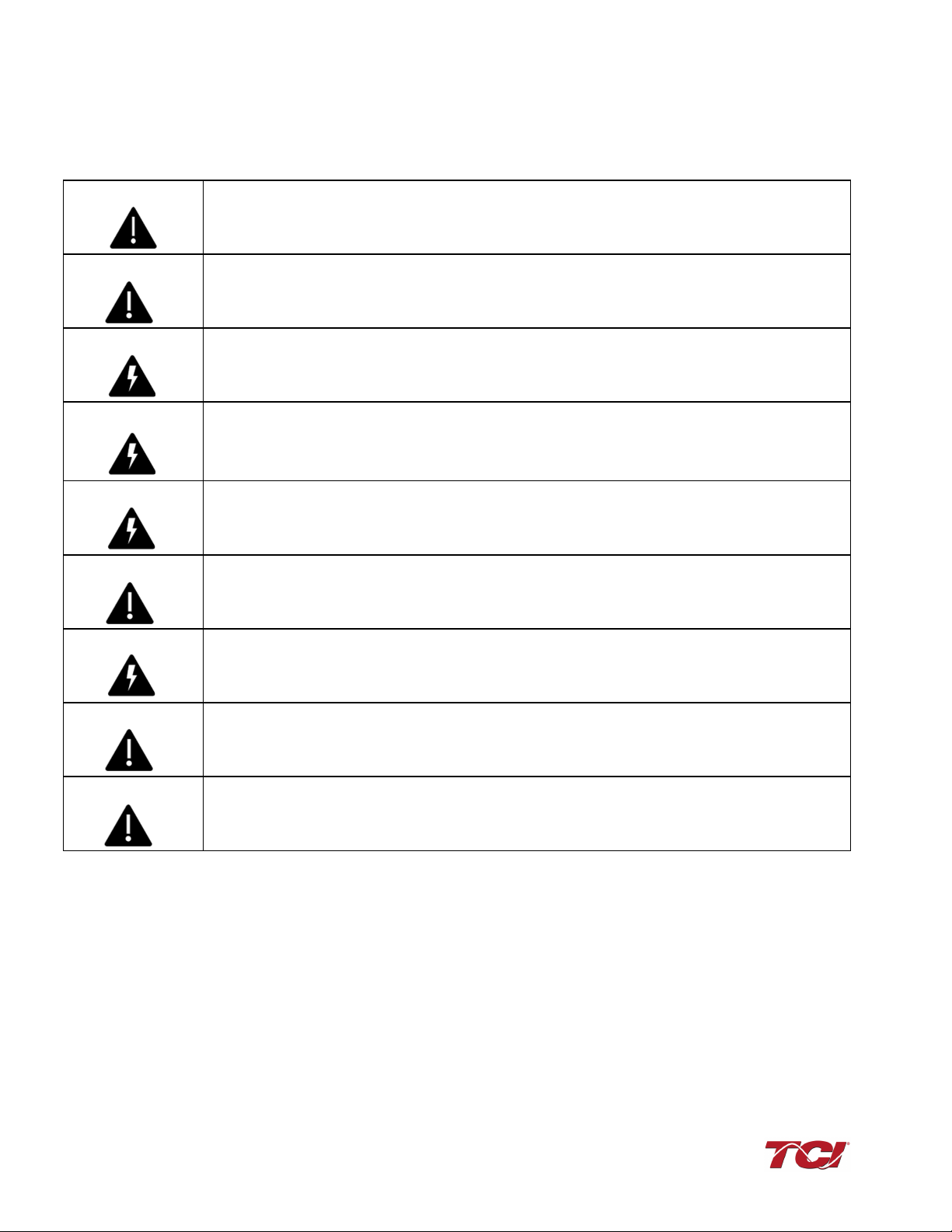
Warnings
Readers are informed of situations that can result in serious physical injury and/or serious
damage to equipment with warning statements marked with the following symbols:
Warning
Dangerous Voltage Warning: warns of situations in which a high voltage can cause physical
injury and/or damage equipment. The text next to this symbol describes ways to avoid the
danger.
Warning General Warning: warns of situations that can cause physical injury and/or damage
equipment by means other than electrical. The text next to this symbol describes ways to
avoid the danger.
Cautions
Readers are informed of situations that can lead to a malfunction and possible equipment
damage with caution statements:
Caution
General Caution: Identifies situations that can lead to a malfunction and possible equipment
damage. The text describes ways to avoid the situation.
MSD Manual 1.0 Safety
2
General Safety Instructions
These safety instructions are intended for all work on the MotorShield™. Additional safety
instructions are provided at appropriate points on other sections of this manual.
Warning
Be sure to read, understand, and follow all safety instructions.
Warning Dangerous Voltage is used in the operation of the MotorShield™. Only qualified electricians
should carry out all electrical installation and maintenance work on the MotorShield™.
Warning Do not attempt any work on a powered MotorShield™.
All sources of power must be disconnected before working on the MotorShield™.
Warning
After removing power, always allow 5 minutes for the capacitors in the MotorShield™ and in
the drive to discharge before working on the MotorShield™, the drive, the motor, or
connecting wiring. Verify with a voltmeter to make sure that all sources of power have been
disconnected and that all capacitors have discharged before beginning work.
Caution The drive output terminals, MotorShield™ and the motor cables are at a dangerously high
voltage when power is applied to the drive regardless of motor operation.
Warning All wiring must be in accordance with the National Electrical Code (NEC) and/or any other
codes that apply to the installation site.
Caution Visually inspect and secure all loose electrical connections before applying power to the
filter. Failure to do so may result in filter damage or diminished filter performance.
Warning The MotorShield™, drive, motor, and other connected equipment must be properly
grounded.
Warning
Prior to operation, confirm the drive operation mode is set to Volts per Hertz mode prior to
operation. Consult the drive manufacturer for proper configuration parameters. Failure to
properly configure the drive could result in drive failure or filter component failure.

MSD Manual 2.0 General Information
3
2.0 General Information
Thank you for selecting the MotorShield™High Performance Sine Wave Filter. TCI has produced
this filter for use in many PWM variable frequency drive (VFD) applications that require low-
distortion sine wave output power. This manual describes how to install, operate, and maintain
the MotorShield™filter.
Intended Audience
This manual is intended for use by all personnel responsible for the installation, operation, and
maintenance of the MotorShield™. Such personnel are expected to have knowledge of electrical
wiring practices, electronic components, and electrical schematic symbols.
Caution
This manual provides general information describing your MotorShield™ filter. More specific
information is provided by the drawings shipped with the unit. Be sure to carefully review the
information provided by these drawings. Information provided by the drawings shipped with
the unit takes precedence over the information provided in this manual.
The ratings, dimensions, and weights given in this manual are approximate and should not
be used for any purpose requiring exact
data. Contact the factory in situations where certified
data is required. All data is subject to change without notice.
Installation Checklist
Adhere to the following installation checklist for a successful installation. These points are
explained in detail in the subsequent sections of this manual.
Receiving Inspection
The MotorShield™has been thoroughly inspected, functionally tested at the factory and carefully
packaged for shipment. When you receive the unit, you should immediately inspect the shipping
•Make sure that the installation location is appropriate for the enclosure type
selected.
•Select a mounting area that will allow adequate cooling air and maintenance access.
•Make sure that all wiring conforms to the requirements of the National Electrical
Code (NEC) and/or other applicable electrical codes.
•Connect the MotorShield™equipment grounding lug to the system ground of the
premises wiring system. Use a properly sized grounding conductor.
•Wire the output power terminals of the VFD, T1(U), T2(V), & T3(W) to the input
terminals of the MotorShield™, U, V, & W.
•Wire the output power terminals, of the MotorShield
™
, T1, T2, & T3 to the motor.
•Connect reactor and capacitor temperature switches to the appropriate fault
monitoring circuit.
•Check the MotorShield™nameplate to ensure rated voltage is appropriate for the
power, drive and motor voltage.
•Make sure that the VFD is set for operating modes and ranges that are compatible
with the MotorShield™.
•Confirm the drive operation mode is set to Volts per Hertz mode prior to operation.
Consult the drive manufacturer for compatibility settings for use with sine wave
filters.
•Check the installation thoroughly before operating the equipment.

MSD Manual 2.0 General Information
4
container and report any damage to the carrier that delivered the unit. Verify that the part number
of the unit you received is the same as the part number listed on your purchase order.
TCI Limited Warranty Policy
TCI, LLC (“TCI”) warrants to the original purchaser only that its products will be free from defects
in materials and workmanship under normal use and service for a period originating on the date
of shipment from TCI and expiring after one (1) year of useful service, not to exceed eighteen
(18) months from the date of shipment.
The foregoing limited warranty is TCI’s sole warranty with respect to its products and TCI makes
no other warranty, representation or promise as to the quality or performance of TCI’s products.
THIS EXPRESS LIMITED WARRANTY IS GIVEN IN LIEU OF AND EXCLUDES ANY AND ALL
EXPRESSED OR IMPLIED WARRANTIES INCLUDING, WITHOUT LIMITATION, ANY IMPLIED
WARRANTY OF MERCHANTABILITY OR FITNESS FOR A PARTICULAR PURPOSE.
This warranty shall not apply if the product was:
a) Altered or repaired by anyone other than TCI;
b) Applied or used for situations other than those originally specified; or
c) Subjected to negligence, accident, or damage by circumstances beyond TCI’s control,
including but not limited to, improper storage, installation, operation or maintenance.
If, within the warranty period, any product shall be found in TCI’s reasonable judgment to be
defective, TCI’s liability and the Buyer’s exclusive remedy under this warranty is expressly limited,
at TCI’s option, to (i) repair or replacement of that product, or (ii) return of the product and refund
of the purchase price. Such remedy shall be Buyer’s sole and exclusive remedy. TCI SHALL
NOT, IN ANY EVENT, BE LIABLE FOR INCIDENTAL DAMAGES OR FOR CONSEQUENTIAL
DAMAGES INCLUDING, BUT NOT LIMITED TO, LOSS OF INCOME, LOSS OF TIME, LOST
SALES, INJURY TO PERSONAL PROPERTY, LIABILITY BUYER INCURS WITH RESPECT TO
ANY OTHER PERSON, LOSS OF USE OF THE PRODUCT OR FOR ANY OTHER TYPE OR
FORM OF CONSEQUENTIAL DAMAGE OR ECONOMIC LOSS.
The foregoing warranties do not cover reimbursement for removal, transportation, reinstallation,
or any other expenses that may be incurred in connection with the repair or replacement of the
TCI product.
The employees and sales agents of TCI are not authorized to make additional warranties about
TCI’s products. TCI’s employees and sales agents’ oral statements do not constitute warranties,
shall not be relied upon by the Buyer and are not part of any contract for sale. All warranties of
TCI embodied in this writing and no other warranties are given beyond those set forth herein.
TCI will not accept the return of any product without its prior written approval. Please consult TCI
Customer Service for instructions on the Return Authorization Procedure.
Storage Instructions
If the MotorShield™is to be stored before use, be sure that it is stored in a location that conforms
to published storage humidity and temperature specifications stated in this manual. Store the unit
in its original packaging.
In the case of long-term storage, defined as any period greater than eighteen (18) months, TCI
Technical Support must be contacted prior to applying power.

MSD Manual 2.0 General Information
5
Product Description
The MotorShield™ is a 3-phase low-pass sine wave filter designed and developed by TCI to
deliver conditioned power to motor loads driven by PWM drives with switching frequencies from 2
kHz to 16 kHz. Any drive control parameter which has the effect of reducing the carrier or
switching frequency below 2 kHz at any time must be disabled. Some sine wave or long lead
mode drive parameters or operating modes can have this effect. This filter is suitable for VFD
drives configured to Volts per Hz modes only. Available for three phase voltage systems up to
460/480 Volts, the MotorShield™ is a passive LC filter connected in series with the output
terminals of the variable frequency drive. This design removes the carrier frequency distortion
from the output voltage waveform resulting in a nearly pure sine wave voltage profile.
The MotorShield™ sine wave filter reduces the effects of the reflected wave phenomenon (dV/dt),
which can cause motor heating, insulation damage, and excessive audible noise. The reduction
of high frequency VFD output currents extends the life of motors and transformers and eliminates
the need for special motor cables. The MotorShield™ reduces VFD ground fault problems and
noise interference in transducer signals caused by stray high frequency harmonic currents.
The MotorShield™ is available in a UL Open Type and Type 1 and Type 3R enclosures which
can be mounted adjacent to the VFD.
The MotorShield™ consists of the following standard features and components:
•An L-C power filter circuit with:
•A TCI 3-phase reactor
•High-endurance, harmonic-rated capacitors
•Compression terminals for ease and integrity of all power wiring
•Thermal switches on reactor and capacitor
•Suitable for all lead lengths extending up to 15,000 feet
MSD Manual 2.0 General Information
6
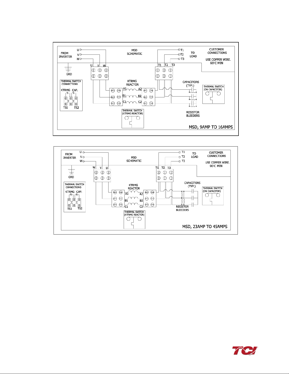
Filter Configuration
Typical Configuration* for MSD 480 V 9A to 16A
Typical Configuration* for MSD 480 V 23A to 45A
Figure 1 - Typical Configurations for the MotorShield™Filter
*These drawings are for general reference only. Use the drawings supplied with the unit for
installation.

MSD Manual 2.0 General Information
7
Typical Configuration* for MSD 480 V 55A
Typical Configuration* for MSD 480 V 65A and up
Figure 2: Typical Configurations for the MotorShield™Filter
*These drawings are for general reference only. Use the drawings supplied with the unit for
installation.
MSD Manual 2.0 General Information
8
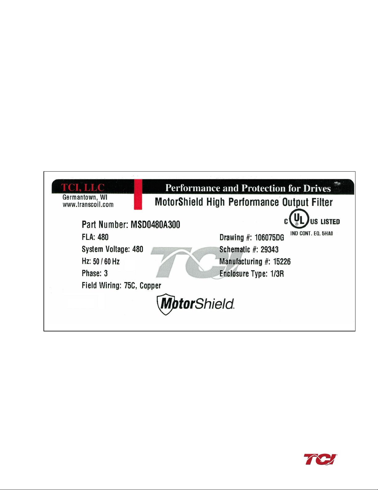
Nameplate Data
Figure 3 shows an example of a MotorShield™nameplate. The following information is marked on
the nameplate:
Part number: encoded model number explained on the following page
FLA: the rated continuous operating current (RMS amps)
System Voltage: the maximum VFD output voltage (fundamental)
Hz: the maximum VFD output frequency (fundamental)
Phase: 3 – The MotorShield™is designed for use only with 3-phase loads.
Drawing and Schematic #: outline and mounting dimension of filter with schematic diagram
Manufacturing #: for TCI internal use
Enclosure Type: UL Type 1 / 3R
Figure 3 – Example of MotorShield™Nameplate
MSD Manual 2.0 General Information
9
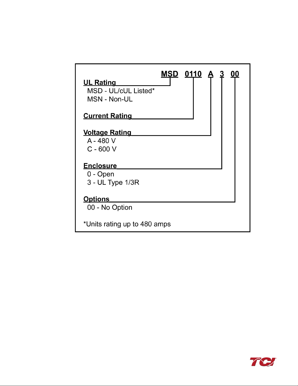
Part Number Encoding
Figure 4 identifies the significance of each character in the MotorShield™model number. The
example model number, MSD0110A300 designates a MotorShield™that is rated 110 Amps, 480
V.
Figure 4 – MotorShield™Model Number Encoding
The MotorShield™has a current rating rather than a horsepower rating. The rating and dimension
tables in the following section list the nominal horsepower ratings corresponding to the current
ratings of the standard models.
Standard Product Ratings and Dimension Tables
The following table lists the ratings and dimensions of the standard MotorShield™ models:

MSD Manual 2.0 General Information
10
Table 1– MSD 480 Volt Models in UL Type 1/3R Enclosures
Model
Number
Horsepower Current
Rating (Amps)
Weight Height
(in.)
Width
(in.)
Depth
(in.)
Watts
Loss
MSD0009A300 5 9
57 lbs
(25.9 Kg)
19.13 in
(49 cm)
15.50 in
(39 cm)
19.50 in
(50 cm)
102
MSD0012A300 7.5 12
58 lbs
(26.3 Kg)
19.13 in
(49 cm)
15.50 in
(39 cm)
19.50 in
(50 cm)
116
MSD0016A300 10 16 58 lbs
(26.3 Kg)
19.13 in
(49 cm)
15.50 in
(39 cm)
19.50 in
(50 cm)
145
MSD0023A300 15 23 75 lbs
(34.0 Kg)
19.13 in
(49 cm)
15.50 in
(39 cm)
19.50 in
(50 cm)
210
MSD0030A300 20 30
75 lbs
(34.0 Kg)
19.13 in
(49 cm)
15.50 in
(39 cm)
19.50 in
(50 cm)
244
MSD0035A300 25 35
75 lbs
(34.0 Kg)
19.13 in
(49 cm)
15.50 in
(39 cm)
19.50 in
(50 cm)
303
MSD0045A300 30 45
90 lbs
(40.8 Kg)
19.13 in
(49 cm)
15.50 in
(39 cm)
19.50 in
(50 cm)
304
MSD0055A300 40 55
105 lbs
(47.6 Kg)
19.13 in
(49 cm)
15.50 in
(39 cm)
19.50 in
(50 cm)
350
MSD0065A300 50 65
144 lbs
(65 Kg)
22.13 in
(56 cm)
20.43 in
(52 cm)
28.50 in
(72 cm)
374
MSD0080A300 60 80
162 lbs
(73 Kg)
22.13 in
(56 cm)
20.43 in
(52 cm)
28.50 in
(72 cm)
546
MSD0110A300 75 110
177 lbs
(80 Kg)
22.13 in
(56 cm)
20.43 in
(52 cm)
28.50 in
(72 cm)
645
MSD0130A300 100 130
187 lbs
(85 Kg)
22.13 in
(56 cm)
20.43 in
(52 cm)
28.50 in
(72 cm)
827
MSD0160A300 125 160 340 lbs
(154 Kg)
36.00 in
(91 cm)
28.40 in
(72 cm)
36.86 in
(94 cm)
683
MSD0200A300 150 200 425 lbs
(193 Kg)
36.00 in
(91 cm)
28.40 in
(72 cm)
36.86 in
(94 cm)
1025
MSD0250A300 200 250
450 lbs
(204 Kg)
36.00 in
(91 cm)
28.40 in
(72 cm)
36.86 in
(94 cm)
1153
MSD0305A300 250 305
460 lbs
(209 Kg)
36.00 in
(91 cm)
28.40 in
(72 cm)
36.86 in
(94 cm)
1290
MSD0362A300 300 362
470 lbs
(213 Kg)
36.00 in
(91 cm)
28.40 in
(72 cm)
36.86 in
(94 cm)
1415
MSD0420A300 350 420
575 lbs
(261 Kg)
36.00 in
(91 cm)
28.40 in
(72 cm)
36.86 in
(94 cm)
1210
MSD0480A300 400 480
630 lbs
(286 Kg)
36.00 in
(91 cm)
28.40 in
(72 cm)
36.86 in
(94 cm)
1460
MSN0540A300 450 540
700 lbs
(318 Kg)
63.95 in
(163 cm)
24.58 in
(62 cm)
44.00 in
(112 cm)
1610
MSN0600A300 500 600
713 lbs
(323 Kg)
63.95 in
(163 cm)
24.58 in
(62 cm)
44.00 in
(112 cm)
1715
MSN0750A300 600 750
805 lbs
(365 Kg)
63.95 in
(163 cm)
24.58 in
(62 cm)
44.00 in
(112 cm)
1805
MSN0850A300 700 850 850 lbs
(386 Kg)
63.95 in
(163 cm)
24.58 in
(62 cm)
44.00 in
(112 cm)
2065
MSN0960A300 800 960
875 lbs
(340 Kg)
63.95 in
(163 cm)
24.58 in
(62 cm)
44.00 in
(112 cm)
2195
MSN1080A300 900 1080
980 lbs
(445 Kg)
63.95 in
(163 cm)
24.58 in
(62 cm)
44.00 in
(112 cm)
2570
MSN0600A300
500
600
64.00
24.17
45.00
2500
MSN0750A300
600
750

MSD Manual 2.0 General Information
11
Product Technical Specifications
Table 2 lists the major technical specifications for the MotorShield™.
Table 2 – MotorShield™Technical Specifications
Current Ratings
240 V: 5 – 248 Amps
480 V: 5 – 1080 Amps
600 V: 8 – 500 Amps
Intermittent overload current of 150% for 1 minute out of every
60 minutes
VFD Output Voltage 240 V, 480 V and 600 V, 3-phase, at fundamental base
frequency configured to Volts per Hz
VFD Output Frequency Up to 80 Hz
VFD Carrier Frequency 2 kHz to 16 kHz
Filter Performance
Maximum peak voltage of output waveform
480 V models: 1000 V,
600 V models: 1,500 V
Maximum dV/dt of output waveform
480 V models: 500 V/μs;
600 V models: 1,500 V/μs
Environmental Conditions
Maximum Elevation 6,600 feet (2,000 m), derating required for operation above this
level
Ambient Operating
Temperature Range
-30°C (-22°F) to 40°C (104°F)
Cooling provisions required for operation above this
temperature
Ambient Storage
Temperature Range -40°C (-40°F) to 50 °C (122 °F)
Maximum Humidity 95%, non-condensing
Reference Technical Standards
Enclosure Options UL Open, Type 1/3R enclosure
Voltage Drop 3% at nominal voltage, frequency and rated current
Capacitors High endurance design (no PCBs)
Agency Approvals UL & cULus Listed (up to 480 amps)
MSD Manual 3.0 Pre-Installation Planning
12
3.0 Pre-installation Planning
Verify the Application
Make sure that the MotorShield™is correct for the application. The voltage and current ratings of the
MotorShield™must match the output voltage and current ratings of the connected variable frequency
drive as it is configured for use with the connected motor. Follow NEC and local electrical codes and
regulations for selection and placement of drive and load cables.
Variable Frequency Drive Settings
Make sure that the variable frequency drive will be set for operation modes and ranges that are
compatible with the MotorShield Kit:
•Maximum output frequency: 80 Hz
•PWM switching frequency between 2 kHz and 12 kHz, ideally 4kHz to 8kHz
•Mode of operation: “scalar” or “V/Hz” without DC braking unless the drive application has been
confirmed by TCI Technical Support
•Consult VFD manual for other drive specific recommendations for use with sinewave filters,
specific instructions may include but are not limited to: Disable any variable PWM switching
frequency options and set drive to continuous 3-phase modulation.
Environment
Locating the MotorShield™in a suitable environment will help ensure proper performance and a
normal operating life.
Warning Unless specifically labeled as approved for such use, this equipment is not suitable for use in
an explosive atmosphere or in a "Hazardous (Classified) Location" as defined in article 500
of the National Electrical Code (NEC).
Make sure that the installation location will not be exposed to corrosive or combustible airborne
contaminants, excessive dirt of liquids. The unit must be installed in an environment where it will
not be exposed to:
•Corrosive liquids or gasses
•Explosive or combustible gases or dust
•Excessive airborne dirt and dust
•Excessive vibration [0.152 mm (0.006 in) displacement, 1G peak]
Working Space
Provide sufficient access and working space around the unit to permit ready and safe installation,
operation and maintenance. Make sure that the installation conforms to all working space and
clearance requirements of the National Electrical Code (NEC) and/or any other applicable codes.
Provide sufficient unobstructed space to allow cooling air to flow through the unit.
The widest or deepest portion of the unit enclosure having ventilation openings must be a
minimum of six inches from adjacent walls or other equipment. Any enclosure sides that do not
have ventilation openings should be a minimum of three inches from adjacent walls or other
equipment.
Power Wiring
The conduit and wiring from the output of the variable frequency drive to the motor must be
routed to the MotorShield™and then to the motor. When selecting a mounting location for the
MotorShield™, plan for the routing of the power wiring.
MSD Manual 3.0 Pre-Installation Planning
13
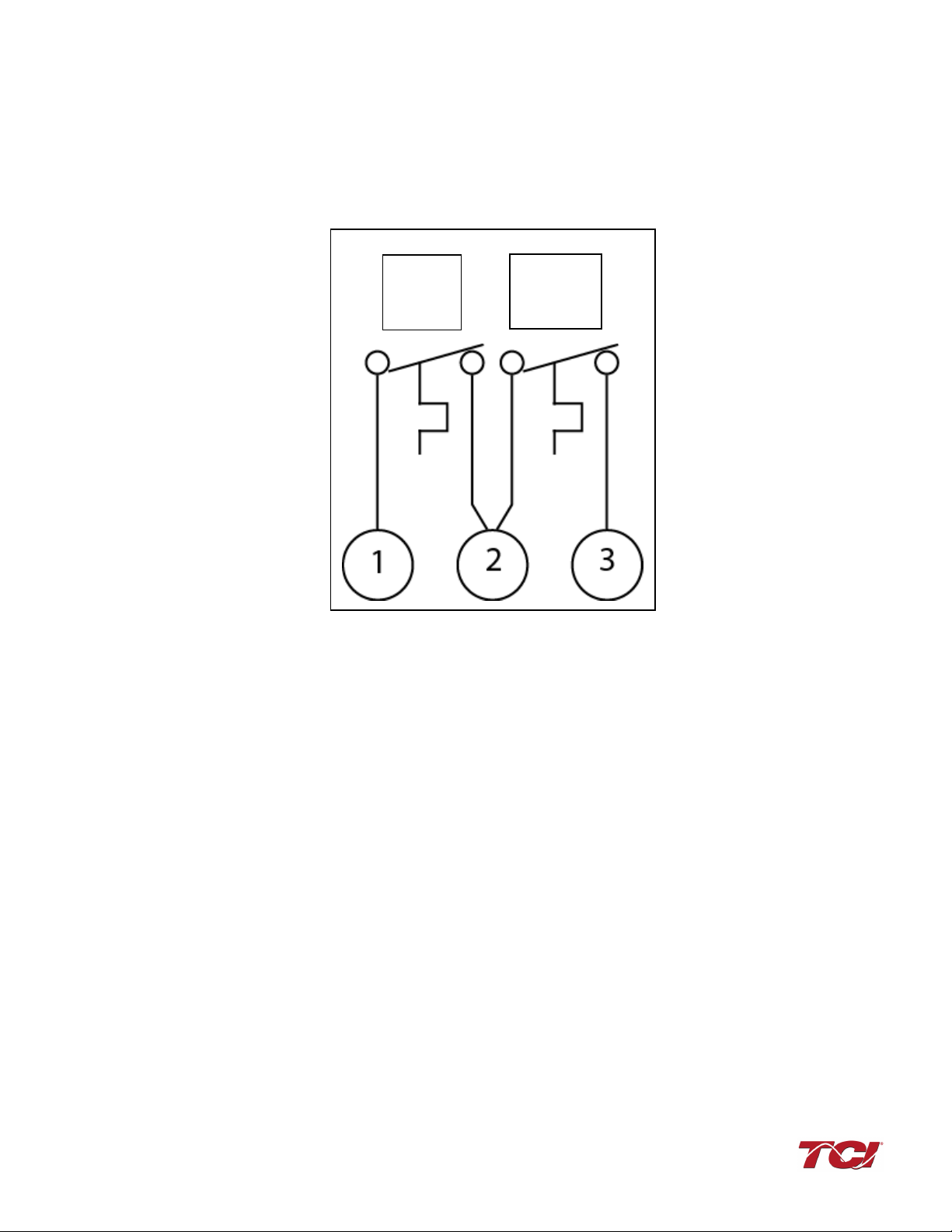
Thermal Switch
Two normally closed thermal switches wired in series. One opens if the filter reactor overheats,
the second opens if the filter capacitors overheat. Connect these switches to monitoring
equipment.
Figure 5: Thermal Switches
Optional Features
Additional wiring requirements may apply to MotorShield™units that are equipped with optional
features. For instructions covering these additional requirements, refer to drawings and/or other
supplemental information furnished with the unit.
Reactor
Thermal
Switch
Capacitor
Thermal
Switch
MSD Manual 4.0 Installation Guidelines
14
4.0 Installation Guidelines
Warning Be sure to read, understand, and follow all safety instructions provided in this manual prior to
beginning work.
Warning
Dangerous Voltage is used in the operation of the MotorShield™. Only qualified electricians
should carry out all electrical installation and maintenance work on the MotorShield™.
Warning All wiring must be performed in accordance with the National Electrical Code (NEC) and/or
any other codes that apply to the installation site.
Wiring
Typical wiring diagrams for filters mounted in UL Type 1 / 3R enclosures can be found in Figure
6.
Before Connecting
Always consult the drive manufacturer’s safety, installation and operation instructions prior to
connecting the MotorShield™to the drive.
Warning
Avoid contact with line voltage when checking for power.
Failure to follow the safety instructions set forth in this manual can result in serious injury or
death.
Warning
Exercise caution when connecting the filter to the drive. Internal filter components may carry
dangerous voltage which can cause death or serious injury upon contact.
Over Temperature Switch
A set of over temperature switches is supplied to prevent damage to the filter in the rare case of
overheating due to abnormal conditions. One switch measures capacitor case temperature, the
other switch measures reactor core temperature.
Table 3: Over Temperature NC Switch
NC Switch opens on over-temperature
Current Amps
Voltage
Contact Load
6
120 AC
Non-Inductive (UL)
4
240 VAC
Non-Inductive (UL)
8
12 VDC
Resistive loads (UL)
4
24 VDC
Resistive loads (UL)
1
120 VDC
Non-Inductive (CSA)
0.7
240 VAC
Non-Inductive (CSA)
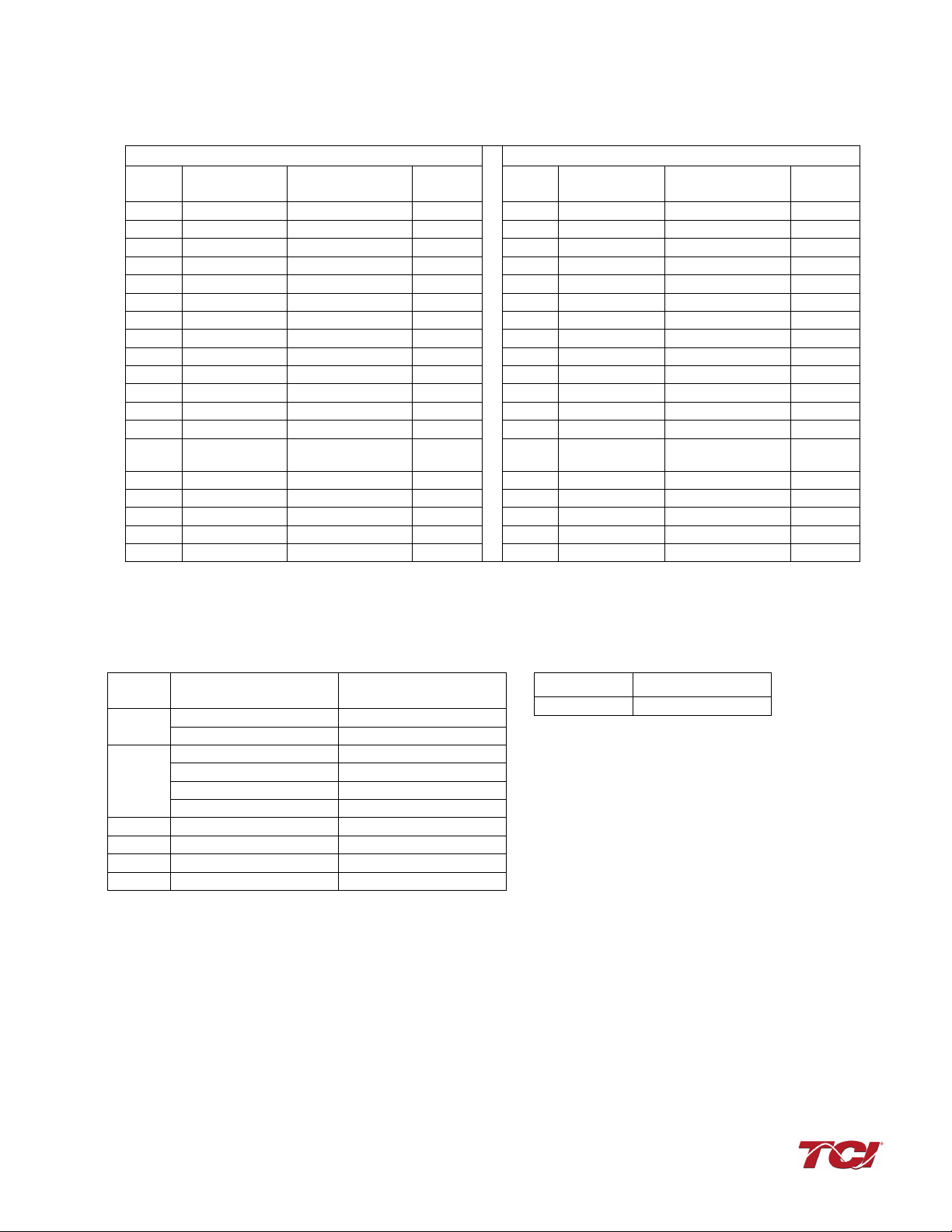
Field Wiring Connection Terminals
Compression type terminals are provided for all field wiring connections. The wire size capacity
ranges and tightening torque for the grounding and power terminals are listed in Tables 4, 5 and
6.
MSD Manual 4.0 Installation Guidelines
15
Table 4 – Motor Power Terminal Wire Size Capacity Range and Tightening Torque (Cu)
Table 5 – Wire Range Table
Wire range Torque
lb.-in
A
1-4 AWG
35 lb.-in (4.0 N-m)
6-14 AWG
30 lb.-in (3.4 N-m)
1/0-3 AWG
50 lb.-in (5.7 N-m)
B
4-6 AWG
45 lb.-in (5.1 N-m)
8 AWG
40 lb.-in (4.5 N-m)
10-14 AWG
35 lb.-in (4.0 N-m)
C
2/0 -3 AWG
50 lb.-in (5.7 N-m)
D
250 kcmil - 4/0 AWG
375 lb.-in (42 N-m)
E
350 kcmil – 1 AWG
375 lb.-in (42 N-m)
F
600 kcmil – 4 AWG
500 lb.-in (57 N-m)
Tab
le 6 – Thermal Switch Block
Wire range Torque (lb.-in)
22-12 AWG
5 lb.-in (0.56 N-m)
Line/Load
Ground
Amps Min*
Wire
Torque
lb.-in
Refer to
Table 5
Amps Min*
Wire
Torque
lb.-in
Refer to
Table 5
9
14 AWG
30 lb.-in (3.4 N-m)
A
9
14 AWG
35 lb.-in (4.0 N-m)
B
12
14 AWG
30 lb.-in (3.4 N-m)
A
12
14 AWG
35 lb.-in (4.0 N-m)
B
16
12 AWG
30 lb.-in (3.4 N-m)
A
16
12 AWG
35 lb.-in (4.0 N-m)
B
23
10 AWG
30 lb.-in (3.4 N-m)
A
23
10 AWG
35 lb.-in (4.0 N-m)
B
30
10 AWG
30 lb.-in (3.4 N-m)
A
30
10 AWG
40 lb.-in (4.5 N-m)
B
35
8 AWG
30 lb.-in (3.4 N-m)
A
35
8 AWG
40 lb.-in (4.5 N-m)
B
45
8 AWG
30 lb.-in (3.4 N-m)
A
45
8 AWG
45 lb.-in (5.1 N-m)
B
55
6 AWG
35 lb.-in (4.0 N-m)
A
55
6 AWG
45 lb.-in (5.1 N-m)
C
65
6 AWG
45 lb.-in (5.1 N-m)
C
65
6 AWG
45 lb.-in (5.1 N-m)
C
80
4 AWG
50 lb.-in (5.7 N-m)
C
80
4 AWG
50 lb.-in (5.7 N-m)
C
110
2 AWG
50 lb.-in (5.7 N-m)
C
110
2 AWG
50 lb.-in (5.7 N-m)
C
130
1 AWG
50 lb.-in (5.7 N-m)
D
130
1 AWG
375 lb.-in (42 N-m)
D
160
2/0 AWG
375 lb.-in (42 N-m)
D
160
2/0 AWG
375 lb.-in (42 N-m)
D
200
3/0
(Two 1/0 AWG)
375 lb.-in (42 N-m)
E
200
3/0
(Two 1/0 AWG)
375 lb.-in (42 N-m)
E
250
Two 1/0 AWG
375 lb.-in (42 N-m)
E
250
Two 1/0 AWG
375 lb.-in (42 N-m)
E
305
Two 2/0 AWG
375 lb.-in (42 N-m)
E
305
Two 2/0 AWG
375 lb.-in (42 N-m)
E
362
Two 4/0 AWG
375 lb.-in (42 N-m)
E
362
Two 4/0 AWG
375 lb.-in (42 N-m)
E
420
Two 300 kcmil
500 lb.-in (57 N-m)
F
420
Two 300 kcmil
500 lb.-in (57 N-m)
F
480
Two 350 kcmil
500 lb.-in (57 N-m)
F
480
Two 350 kcmil
500 lb.-in (57 N-m)
F
* A larger wire can be used. See referenced table for wire range and torque.
600
600
750
750

MSD Manual 4.0 Installation Guidelines
16
Connection Diagram
Figure 6 shows the typical wiring connections between the MotorShield™and the VFD and motor.
Refer to the instructions for the VFD or other equipment to which the fault contact is connected.
To prevent damage due to abnormal over temperature conditions, the use of an optional thermal
interlock circuit with thermal switch is recommended to shut down the drive if internal reactor
temperatures exceed its temperature rating.
Figure 6 – Typical Connection Diagram
Grounding
The MotorShield™panel equipment grounding lug must be connected to the ground of the
premises wiring system. The equipment grounding connection must conform to the requirements
of the National Electrical Code (NEC) and/or any other codes that apply to the installation site.
The ground connection must be made using a wire conductor. Metallic conduit is not a suitable
grounding conductor. The integrity of all ground connections should be periodically checked.
Power Wiring
Connect the output of the VFD, terminals T1(U), T2(V), & T3(W), to the input of the MotorShield™,
terminals U, V, & W. Connect the motor to the output of the MotorShield™, terminals T1, T2, & T3.
Caution
Use wire that is appropriate for the voltage and current rating of the motor.
Use copper wire with an insulation temperature rating of 90°C or higher.
The wire size and the voltage ratings must conform to the requirements of the National
Electrical Code (NEC) and/or other applicable electrical codes.
Be sure to also follow the motor wiring instructions provided in the instruction manual for the
VFD.
This manual suits for next models
24
Table of contents
Popular Industrial Electrical manuals by other brands


Murata
Murata GRM033R61C223KE84 Series Reference sheet

Murata
Murata GRM0335C1H7R0DA01 Series Reference sheet

Murata
Murata GRM21BR71C475KA73 Series Reference sheet

Eaton
Eaton HALO E7 ICAT New Construction Series instructions

Murata
Murata GRM31MR61E106MA12 Series Reference sheet

Assa Abloy
Assa Abloy 118 Series Installation and assembly instructions

Murata
Murata GCM188R72A102KA37 Series Reference sheet

Murata
Murata GRM1555C1H821GA01 Series Reference sheet

Murata
Murata GRM31CR60J157ME11 Series Reference sheet

Murata
Murata GRM0225C1E2R4BA03 Series Reference sheet

Altronix
Altronix TROVE T3MK75F16V installation guide

OEZ
OEZ CS-BC-B014 Instructions for use