TCL L39D30 User manual

TCL
SERVICE MANUAL
39D30 06A$3
1. Caution…………………………………………………………………………2
2. specification……………………………………………………………………6
3. Alignment Procedure…………………………………………………………7
4.Block diagram…………………………………………………………………1
5.Scheme Diagram ……………………………………………………………
5. Troubleshooting………………………………………………………………2
6. PCB Layout …………………………………………………………………3
([SORGHGUDZLQJ
8. BOM list .............................................................................................................34
This m anual i s t he l atest at t he t ime of pr inting, and doe s not
include the modification which may be made after the printing, by
the constant improvement of product

CA UTION: TO RE DUCE THE RIS K OF
ELECTR ICA L SHOCK, DO NOT RE MOVE
COVER (OR BACK). NO USER SERVICEABLE
PAR TS INSIDE . RE FE R SER VIC ING TO
QUALIFIED SERVICE PERSONNEL.
The lighting flash with arrowhead symbol, with an equilateral triangle is intended to
alert the user to the presence of uninsulated voltage within the products
enclosure that may be of sufficient magnitude to constitute a risk of electric shock to
the person.
The exclamation point within an equilateral triangle is intended to alert the user to the
presence of important operating and maintenance (servicing) instructions in the
literature accompanying the appliance.
CAUTION:
Use of controls, adjustments or procedures other than those specified herein may result in
hazardous radiation exposure.
CA U T ION
RISK
RISK OF
ELECTRI
ELECTRIC
SHOCK
SHOCK DO
NOT
NOT
OPEN.
OPEN.
2
dangerous
WARNING: TO REDUCE RISK OF FIRE OR ELECTRIC SHOCK, DO NOT
EXPOSE THIS APPLIANCE TO RAIN OR MOISTURE.
SCHNEIDER ELECTRONICS GMBH-GERMANY
1. CAUTION
2

1. When the power cord or plug is damaged or frayed, unplug this television set from the wall outlet and refer servicing to
qualified service personnel.
2. Do not overload wall outlets and extension cords as this can result in fire or electric shock.
3. Do not allow anything to rest on or roll over the power cord, and do not place the TV where power cord is subject to
traffic or abuse. This may result in a shock or fire hazard.
4. Do not attempt to service this television set yourself as opening or removing covers may expose you to dangerous
voltage or other hazards. Refer all servicing to qualified service personnel.
5. Never push objects of any kind into this television set through cabinet slots as they may touch dangerous voltage
points or short out parts that could result in a fire or electric shock. Never spill liquid of any kind on the television set.
6. If the television set has been dropped or the cabinet has been damaged, unplug this television set from the wall outlet
and refer servicing to qualified service personnel.
7. If liquid has been spilled into the television set, unplug this television set from the wall outlet and refer servicing to
qualified service personnel.
8. Do not subject your television set to impact of any kind. Be particularly careful not to damage the picture tube surface.
9. Unplug this television set from the wall outlet before cleaning. Do not use liquid cleaners or aerosol cleaners. Use a
damp cloth for cleaning.
10.1. Do not place this television set on an unstable cart, stand, or table. The television set may fall, causing serious injury
to a child or an adult, and serious damage to the appliance. Use only with a cart or stand recommended by the
manufacturer, or sold with the television set. Wall or shelf mounting should follow the manufacturer s instructions, and
should use a mounting kit approved by the manufacturer.
10.2. An appliance and cart combination should be moved with care. Quick stops, excessive force, and uneven surfaces
may cause the appliance and cart combination to overturn.
CAUTION:
Read all of these instructions. Sa ve these instructions for later use . Follo w all Warnings and
Instructions marked on the audio equipment.
1. Read Instructions-All the safety and operatinginstructionsshouldbe read before the productis operated.
2. Retain Instructions- The safety and operating instructions should be retained for future reference.
3. Heed Warnings- All warnings on the product and in the operating instructions should be adhered to.
4. Follow Instructions- All operating and use instructions should be followed.
3
SCHNEIDER ELECTRONICS GMBH-GERMANY
IMPORTANT SAFETY INSTRUCTIONS
FOR YOUR PERSONAL SAFETY
3

11. Do not use this television set near water ... for example, near a bathtub, washbowl, kitchen sink, or laundry tub, in a
wet basement, or near a swimming pool, etc.
Never expose the set to rain or water. If the set has been exposed to rain or water, unplug the set from the wall
outlet and refer servicing to qualified service personnel.
12. Choose a place where light (artificial or sunlight) does not shine directly on the screen.
13. Avoid dusty places, since piling up of dust inside TV chassis may cause failure of the set when high humidity persists.
14. The set has slots, or openings in the cabinet for ventilation purposes, to provide reliable operation of the receiver, to
protect it from overheating. These openings must not be blocked or covered.
Never cover the slots or openings with cloth or other material.
Never block the bottom ventilation slots of the set by placing it on a bed, sofa, rug, etc.
Never place the set near or over a radiator or heat register.
Never place the set in enclosure, unless proper ventilation is provided.
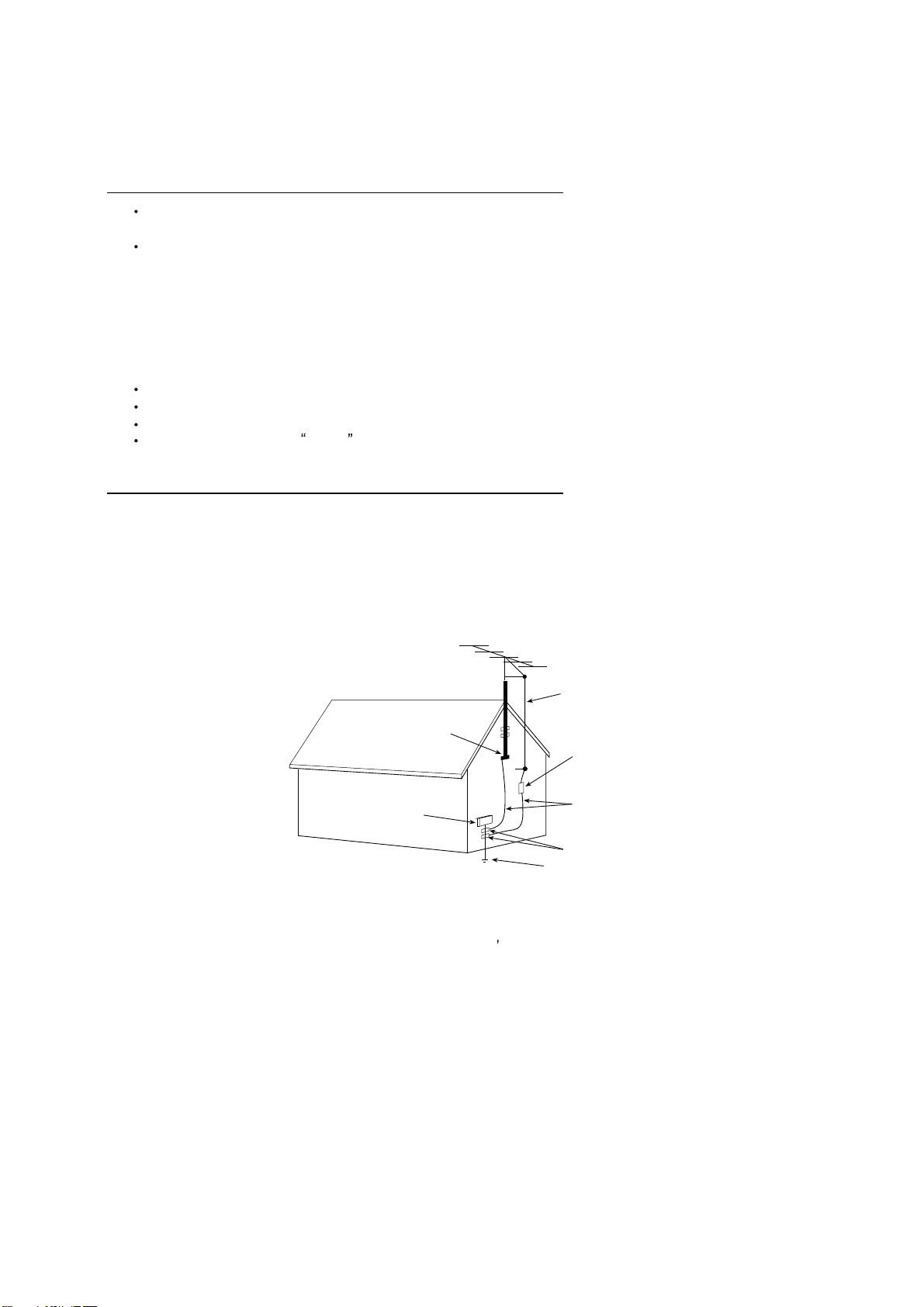
15.1. If an outside antenna is connected to the television set, be sure the antenna system is grounded so as to provide some
protection against voltage surges and built up static charges, Section 810 of the National Electrical Code, NFPA No.
70-1975, provides information with respect to proper grounding of the mast and supporting structure, grounding of the
lead-in wire to an antenna discharge unit, size of grounding conductors, location of antenna discharge unit, connection
to grounding electrode, and requirements for the grounding electrode.
15.2. Note to CATV system installer : (Only for the television set with CATV reception)
This reminder is provided to call the CATV system attention to Article 820-40 of the NEC that provides
guidelines for proper grounding and, in particular, specifies that the cable ground shall be connected to the grounding
system of the building, as close to the point of cable entry as practical.
16. An outside antenna system should not be located in the vicinity of overhead power lines or other electric lights or power
circuits, or where it can fall into such power lines or circuits. When installing an outside antenna system, extreme care
should be taken to keep from touching such power lines or circuits as contact with them might be fatal.
17. For added protection for this television set during a lightning storm, or when it is left unattended and unused for long
periods of time, unplug it from the wall outlet and disconnect the antenna. This will prevent damage due to lightning
and power-line surges.
ANTENNA
LEAD- IN WIRE
ANTENNA DISCHARGE
UNIT (NEC SECTION
810-20)
GROUNDING
CONDUCTORS
(NEC SECTION810-21)
GROUND CLAMPS
POWER SERVICE GROUNDING
ELECTRODE SYSTEM
(NEC ART 250. PART H)
ELECTRIC SERVICE
EQUIPMENT
GROUND CLAMP
NEC-NATIONAL ELECTRICAL CODE
EXAMPLE OF ANTENNA GROUNDING AS PER
NATIONAL ELECTRICAL CODE
EXAMPLE OF ANTENNA GROUNDING AS PER NATIONAL ELECTRICAL CODE INSTRUCTIONS
a built-in
installer s
4
SCHNEIDER ELECTRONICS GMBH-GERMANY
PROTECTION AND LOCATION OF YOUR SET
4

18.
This television set should be operated only from the type of power source indicated on the marking label.If you are not
sure of the type of power supply at your home, consult your television dealer or local power company. For television
sets designed to operate from battery power, refer to the operating instructions.
19. If the television set does not operate normally by following the operating instructions, unplug this television set from the
wall outlet and refer servicing to qualified service personnel. Adjust only those controls that are covered in the operating
instructions as improper adjustment of other controls may result in damage and will often require extensive work by a
qualified technician to restore the television set to normal operation.
20. When going on a holiday : If your television set is to remain unused for a period of time, for instance, when you go on
a holiday, turn the television set and unplug the television set from the wall outlet.
21. If you are unable to restore normal operation by following the detailedprocedurein your operatinginstructions,
do not attempt any further adjustment. Unplug the set and call your dealer or service technician.
22. Whenever the television set is damaged or fails, or a distinct change in performance indicates a need for
service, unplug the set and have it checked by a professional service technician.
23. It is normal for some TV sets to make occasional snapping or popping sounds, particularly when being
turned on or off. If the snapping or popping is continuous or frequent, unplug the set and consult your
dealer or service technician.
24. Do not use attachments not recommendedby the television set manufacturer as they may cause hazards.
25. When replacementparts are required, be sure the service technicianhas used replacementparts specified
by the manufacturer that have the same characteristics as the original part. Unauthorized substitutions
may result in fire, electric shock, or other hazards.
26. Upon completion of any service or repairs to the television set, ask the service technician to perform
routine safety checks to determine that the television is in safe operating condition.
off
5
SCHNEIDER ELECTRONICS GMBH-GERMANY
OPERATION OF YOUR SET
IF THE SET DOES NOT OPERATE PROPERLY
FOR SERVICE AND MODIFICATION
5

TCL MULTIMEDIA
FTV PRODUCT MANAGEMENT DEPT.
SPECIFICATION RELEASE
Version: V1.0 Issued Date: 2012.03.16
PICTURE
Category LED TV
Naturalight Technology
Yes (Dynamic Backlight II)
Dynamic Contrast Yes
Color Temperature Warm / Normal / Cold SIGNAL FORMAT CAPABILITY
Backlight Adjustable Yes Component Video Format Y,Pb/Cb,Pr/Cr:up to 1080P
Scaler Mode Full, Subtitle, Wide screen ,4:3, Nature,Original DVI Video Format Up to XGA for HDMI-PC
Picture Effect Standard, Bright, Soft and Personal HDMI Video Format up to 1080P
Film Mode (3:2 pull down) AUTO PC Compatibility Up to SXGA
VGA Dot to Dot Display Yes (Nature) TERMINALS
Audio/CVBS Input (Composite) 2 R/L+2 Video: AV1, AV2(Side)
S-Video Input X
Audio Input for S-Video X
Comb Filter 3D YPbPr Input 1
Dynamic Noise Reduction 3D Audio Input for YPbPr 1
Adaptive Deinterlacing 3D YCbCr Input Share with "YPbPr"
Blue Stretch Yes Audio Input for YCbCr Share with Audio for "YPbPr"
Black Stretch Yes VGA Input(RGB) 1 (D-Sub,15 Pins)
Motion Compensation Yes Audio Input for RGB Share with Audio for "YPbPr"
DLTI Yes DVI Share with "HDMI" PORT
DCTI Yes Audio Input for DVI Share with Audio for "YPbPr"
Dynamic Skin Correction Yes HDMI 1 (HDMI1)
Audio/CVBS Output (Composite) 1 (R/L+CVBS)
PANEL SPECIFICATION SPDIF Output X
Back light Unit LED Headphone Output X
Panel supplier CMC RF Input(Antenna) 1 (IEC Type)
Aspect Ratio 16:9 USB 1(at side)
Panel Size (inch) 39 BASIC INFO.
Display Resolution 1920*1080 TV System PAL/SECAM B/G.D/K,PAL-I ;NTSC-M
Brightness (cd/m2) 350 AV System PAL,NTSC,SECAM
Contrast Ratio
5000:1 Channels 199(1~199)
Response Time 8.5ms (G to G) Chassis MS82-AP
Viewing Angle (H/V) 178°/178° Certification CB/3C
Life Time 50000hrs (Typ.) Power Supply AC 110V-240V 50/60Hz
Color 16.7M Power Consumption-TV on 90W
SOUND Power Consumption-Standby
<1W
Speakers Integrated speakers (Two mediant) Default Color of Front Cabinet Black
Audio Power Output 2×8W Keyboard Position on the left side
Base Stand Detachable Yes
Sound Effect Stereo, Music, Movie, News,Personal Unpackaged Dimension for Main Body (L*H*D) (mm)
Sound Control Balance, Sound EQ Adjust; With Base Stand (mm) 913*231*603mm
Without Base Stand (mm) 913*78*571mm
Packaged Dimension (L*H*D) 1040*177*672mm
Main Body (mm)
Speaker Box --
FUNCTION Base Stand Packaged with ALL
OSD Language English/Vietnam/French/Russian/Thai/Arabian/Persian Net Weight (Kg) 12.5
OSD Features Motion Bmp Style Gross Weight (Kg) 14.5
Source in OSD Source Bmp Icon Selecting Container Loading
Teletext X 20 feet 229
Clock/Sleep Timers Yes 40 feet 475
Wake up/Turn off time Yes 40 feet high 543
Wake up Source/Chanel Yes ACCESSORIES
Watch Time Limit Yes Operation Manual English(Default)
Startup Setting Yes(User can set a picture for turning on Logo display) Remote Control RC200 B (with two batteries)
Smart Switch(AIS) Yes(Signal Auto Detecting and Changing Source) Base Stand Integrated Packaging
Picture Freeze Yes Speaker Box Integrated
Movie Show:Support H.264、RM/RMVB、Wall Mount Optional
VC1、MPEG4、MPEG2;Others AC Power cord
Photo Show: Suppor JPEG、BMP、PNG;
Music Show: support MP3、WMA;
Hotel In factory mode
Design and specifications are subject to change without notice!
Model: L39D30/MS82-AP
Drafted by: Huangdq
Picture Enhancement
Approved by:
USB Connection

第1页共 11 页
CRT 事业部
CRT 设计中心
Alignment Procedure
(MODEL):MS82/MS82A Series
VERSION:V1.0
PREPARED BY : HAN CHUNYU DATE : 2011-10-31
APPROVEDBY: DATE:
文件编号:CRT/SJ/FK02-2010
序号:

第2页共 11 页
History Description of major changes Release Date
V1.0 2011-09-08
1.Overview
MS82/MS82A chassis is designed for Asia Pacific/South America market.
Both Full HD panel and HD panel can be compatible. The signal sources
include TV,AV,YPBPR/YCBCR,VGA,HDMI and USB. For YPBPR,HDMI
source ,Format up to 1080p can be supported; USB support image, audio and
video(up to H.264)playing; SPDIF and AV output is available too. The whole
process of alignment includes ADC calibration and White Balance
adjustments.
2.Factory Menu
1、Methods of Entering
Method 1:Using the remote ,enter the “Picture” submenu in the OSD;
choosing the “contrast” item and press the 9,7,3 and 5 in series,
Factory Menu will appear in the left top of screen
Method 2:Press RETURN button when FACTORY HOTKEY is enabled(ON).
2. General introduction
FACTORY MENU
ITEMS Default
Setting
Description Status
1-FAC HOTKEY OFF Factory hotkey Switch (OFF/ON).Should be OFF
after factory alignment
OK
2-WARM UP OFF OFF:The set would enter standby mode after 15
minutes without input signal;
ON:Aging mode. Aging time will display on the
left bottom of screen.
OK
3-ADC ADC calibration(refer as follow) OK
4-WHITE
BALANCE
White Balance data adjustment(refer as follow)
The balance data is set by PE before the mass
production. Do not need adjust.
OK

第3页共 11 页
5-SHOP DO Reset the set after production alignment;(This
operation will remove all unnecessary factory
value; The factory hotkey will be turn off)
OK
6-NVM reset DO System initialization. Restore all data except
the White Balance and ADC data ;Only for R&D.
OK
7-SET FAC CH DO Preset specific factory channels for specific
factory. Press left and right button to select
the factory, and then press OK to confirm.
OK
8-POWER ON
LAST ON: Always turns on TV when AC power on
STB:Always goes to standby mode when AC power
on
LAST:Restore the status before the last AC power
off
OK
9-USB UPDATE USB update,(refer as follow) OK
Note: Below the factory menu, some model information are showed, including
software version, Project Name, SIACP Version, and SW release time.
ADC Submenu:
ITEMS Default
Setting
Description Status
Source RGB/YPbP
r
(HD)
Sources need calibration. RGB means PC and
YPbPr(HD) means YPbPr
OK
R-GAIN 128 R-OFFSET OK
G-GAIN 128 G-OFFSET OK
B-GAIN 128 B-OFFSET OK
R-OFFSET 128 R-GAIN OK
G-OFFSET 128 G-GAIN OK
B-OFFSET 128 B-GAIN OK
AUTO ADC WAIT/OK With appropriate pattern (mentioned below)
inputted, press left or right key to start auto
calibration.
OK
WHITE BALANCE Submenu
ITEMS Default
Setting
Description Statu
s

第4页共 11 页
Source Current
Source
Current Source( TV,AV1/AV2/YPbPr, HDMI need
adjustment)
OK
COLOR TEMP NORMAL NORMAL/COOL/WARM OK
R-GAIN 128 R-GAIN OK
G-GAIN 128 G-GAIN OK
B-GAIN 128 B-GAIN OK
R-OFFSET 128 R-OFFSET OK
G-OFFSET 128 G-OFFSET OK
B-OFFSET 128 B-OFFSET OK
WB INIT DO ONLY FOR TCL R&D OK
The first step is to adjust HDMI.
3.Design Menu
1、Methods of Entering:
Method 1:Using the remote, enter the “Picture” submenu in the OSD; choosing
the “contrast” item and press the 1,9,5,and 0 in series ,Design Menu will
appear in the left top of screen.
Method 2: Press RETURN button when DESIGN HOTKEY is enabled (ON).
2、General introduction
DESIGN MENU
ITEMS Default
Setting
Description Status
1-DESIGN
HOTKEY
OFF ON/OFF OK
2-FACTORY
MENU
ON/OFF OK
3-SHOP INIT Default setting submenu after production
alignment refer to **
OK
4-OTHER Other set .Only for TCL R&D OK
5-SERVICE
MENU
After service menu description OK

第5页共 11 页
6-PARAM
SETTING
Parameter setting submenu OK
7-HOTEL
MENU
Hotel submenu OK
8-LANGUAGE
MENU
Language switch OK
SHOP INIT submenu
ITEMS Default
Setting
Description Status
Volume 30 0-100 adjustable OK
PIC MODE STANDARD STANDARD/BRIGHT/SOFT/PERSONAL OK
SOUND MODE STEREO STEREO/MUSIC/MOVIE/NEWS/PESONAL OK
Channel 199 0-199 adjustable OK
Language English Up to 7 languages optional OK
COLOR SYS AUTO AUTO、PAL、 NTSC、SECAM OK
SOUND SYS DK DK、BG、I、M OK
PRESET CH 1 0-199 adjustable OK
COLOR TEMP NORMAL NORMAL、WARM、COOL OK
Other
ITEMS Default
Setting
Description Status
VIF1 VIF adjust OK
VIF2 VIF adjust OK
VIF3 VIF adjust OK
QMAP
ADJUST
PQ debug OK
SSC SSC adjust OK
DBC ENABLE DBC adjust OK
BP OK
CP OK
DBC MODE OK
MIU DQS0
MIU DQS1
TELETEXT ON TELETEXT SWITCH (only for MS82A series) OK

第6页共 11 页
NICAM ON NICAM SWITCH (only for MS82A series) OK
PARAM SET SETTING
ITEMS Default
Setting
Description Status
Brightness
Curve Brightness curve. Exclusively used by R&D OK
Contrast
Curve Contrast curve. Exclusively used by R&D OK
Saturation
Curve Saturation curve. Exclusively used by R&D OK
Hue Curve Hue curve. Exclusively used by R&D OK
Sharpness
Curve Sharpness curve. Exclusively used by R&D OK
Volume Curve Volume curve. Exclusively used by R&D OK
BackLight
Curve BackLight curve. Exclusively used by R&D OK
LANGUAGE MENU SETTING
ITEMS Default
Setting
Description Status
1-FRENCH: On FRENCH OK
1-VIETNAMESE: On VIETNAMESE OK
1-RUSSIAN: On RUSSIAN OK
1-ARABIC: On ARABIC OK
1-FARSI: On FARSI OK
1-THAI: On THAI OK
4、Service Menu
1、Methods of Entering
Using the remote, enter the “Picture” submenu in the OSD; choosing the
“contrast” item and press the 9,7,0 and 5 in series, Service Menu will appear in
the left top of screen
SERVICE MENU:
ITEM Default
Setting
Description Status
SW NO Software Version OK

第7页共 11 页
DATE Date and time of software releasing OK
Project Name Module name OK
SIACP
VERSION
SIACP VERSION OK
Chassis MS82 Chassis name OK
PANEL P/N of panel OK
NG
PROJECT ID Project Select submenu OK
PWON_MUSIC ON Power on music
USB UPDATE USB UPDATE ok
HOTEL ENABLE OFF HOTEL MENU SWITCH ok
ERROR CODE OFF Error prompt OK
POWER_LOGO TCL/HYUDNA
I
Select the logo of customer 0K
LOGO_LIGHT ON LOGO LIGHT SWITCH OK
TCL_SHOW ON TCL SHOW SWITCH OK
5. Debugging
5.1. General Steps of debugging
According to the requirement of the order, below steps are needed for
appropriate setting.
1) Enter the Factory Menu, enable FAC HOTKEY.
2) Check Project ID and the version of software, release date displayed
at the bottom of Factory Menu.
3) Enter Design Menu, choose SERVICE MENU->Project ID, choose
corresponding Project ID number of the product (Refer to the
“V6-PROJECT -ID0**”in the BOM list).
4) Return to Factory Menu, check the Product model.
5) Choose Factory Menu->NVM RESET and press the right button of the
remote and wait until prompt OK appears.
6) Restart the set
7) According to the requirement of the order, Set the items of SHOP
INIT and Hotel Menu etc.
8) After aging under normal temperature, calibrate ADC and adjust
white balance.
9) Choose Factory Menu ->SHOP and press the button of remote to
initialize the set.

第8页共 11 页
Note: After step 9, Hotel Menu will be disabled by default. Therefore,
if the order requires hotel function, it is necessary to enable hotel
function by set Design MENU->Service Menu->HOTEL ENABLE to ON.
5.2. Equipments
·Color Analyzer CA-210.
·Video Pattern Generator Chroma2329.
·Color TV Pattern Generator PM5418/Fluke5418.
·VGA cable , AV(RCA) cable ,YPBPB (RCA) cable, HDMI cable etc.
5.3. ADC Calibration
5.3.1. Signal and generator
PC: Chroma2329 Pattern 42,Timing 14(1024X768@60Hz 5 MOSAIC)
YPBPR: Chroma2329 pattern 103, Timing 79(100% Color Bar,720p)
5.3.2. Steps of Calibration:
1). Access to the Factory menu->ADC
2). select RGB source and see the 5 MOSAIC appear on the screen
3). Select AUTO ADC , Press the right button on the your remote to calibrate
the ADC automatically.
4). Select YPBPR source and Repeat step 5.3 .
When the OK appears the calibration has been finished successfully.

第9页共 11 页
5.4. White Balance adjustments (Manual)
Before adjustment ,you must make sure the ADC status(only PC and YPbPr)
is “success”and Color Analyzer has been calibrated .Only
AV1,YPbPr,PC,HDMI1 need to be adjusted. HDMI1 should be the first.
5.4.1. Signal and generator
The pattern of the signal should be used are White (Chroma2329 pattern
113) and Grey (pattern 114).
The format of signal are respectively 720P for HDMI1 (Chroma2329
Timing 69),PAL (Chroma2329 Timing38) for AV1,1024X768@60Hz(Chroma2329
Timing14) for VGA and 720P(Chroma2329 Timing79) for YPbPr.
5.4.2. Steps of adjustment
1).Enter the factory menu-> White Balance, select source HDMI 1 and
Normal Temperature.
2).Input grey signal in 720p format.
3).Change R-OFFSET and B-OFFSET to make sure the value of color
coordination equal to (X=0.280 +/-0.015;Y=0.290 +/-0.015).
4).Input white signal in 720p format.
5). Change R-GAIN and B-GAIN to make sure the value of color
coordination equal to (X=0.280 +/-0.015;Y=0.290 +/-0.015).
6).Repeat step 2—5 until both of the value of color coordination of
white and grey equal to (X=0.280 +/-0.015;Y=0.290 +/-0.015).
For COOL and WARM color temperature, just repeat step 2—5.The color
coordination we recommend for COOL and WARM color temperature is
respectively(X=0.270 +/-0.015;Y=0.270 +/-0.015) and
(X=0.300 +/-0.015;Y=0.305 +/-0.015).

第10 页共 11 页
After the adjustment of HDMI1, you can switch to other source AV1,
PC and YPbPr and repeat step 1—6 to do the WB adjustment.
Note: For some small size LED panel,the color coordination of
specifications is not X=0.280/Y=0.290,and we recommend you adopt the
values from panel specifications.
5.5. ADC Calibration and White Balance Adjustment (automatic)
The process of adjusting ADC and White Balance automatically is out
of the range of this file, Please refer to the relevant technical file
of HuiZhou factory of TCL.
6.Chip list of software programming before SMT
Following chips must be programmed before SMT by tools
Position Chip type Software description
U204 M24C64 System Software
U203 EN25Q32 HDMI HDCP Key
7.Software update
Method of SW update:
1, Download the bin file “MS82UP.bin”to the root directory of your USB
device (DO not change the file name); Then insert the USB device to USB
interface of TV set.
2,using the remote, enter the “Picture” submenu of the OSD; choosing
the “contrast” item and press 9,7,3 and 5 in series, Factory Menu will
appear in the left top of screen.
3,Select the “USB UPDATE” item , press left or right key to enter the
update box;
4,Select “YES” of the dialog box and press OK button to start the update,
you will see a progress box on the screen.
5,After updating , the set will reset automatically.
8, Project ID selecting
1) Press the Menu button of remote control, then select Contrast item
of Picture submenu; press 1,9,5,0 consecutively, there you go the
Design Menu.
2) Select the SERVICE MENU item, press OK and RIGHT button of the remote
to enter submenu,
3) Select the PROJECT ID item, press OK or RIGHT button of the remote
to enter the submenu;

第11 页共 11 页
4) Press the right or left button of the remote to select the ID you want;
5) After ID selection, press MENU button of the remote to exit DESIGN
MENU.
6) Finally, do AC power on/off.

MS82 POWER
DIMMING
33V
BL_ON/OFF
P_ON/OFF +3V3_SBY/5VMST +3_3VSTB
5V
0(R881)
3
.
3V
172MA
MP2127(U803)
V 1V28 680MA
AS1117_3.3(U801)
5V
电
MP2127(U803)
V
_
1V28
680MA
AS1117S18(U808) +1V8(DDR)469MA
源板 +24/12v +2V5 250MA
AS1117_2.5(U802)
RT8110B 5VAIN ASZ1117_3.3(U800) +3V3 110MA
兼容电源无开
关Q800 +12
PMK65XP
屏
ON_PANEL
+5V OR +12V
R806 /R807可选择屏
是5V还是12V供电
MP1593DZ
+24/12v +12v
屏

DGND
DGND
T
DGND
DGND
DGND
DGND
DGND
T
DGND
DGND
DGND
DGND
DGND
DGND
DGND
DGND
DGND
DGND
DGND
DGND
DGND
DGND DGND
DGND
DGND
DGND
DGND
DGND
DGND
T
T
DGND
T
T
T
T
TTT
T
T
T
DGND
DGND
T
SDA
SCL
WC
VCC
VSS
E2/NC
E1/NC
E0/NC
DGND
T
DGND
DGND
T
DGND
DGND
DGND
TT
DGND
T
DGND
T
TT
T
DGND
DGND
DGND
DGND
DGND
DGND
DGND
DGND DGND
TT
T
T
DGND
DGND
T
T
T
DGND
DGND
DGND
DI
CLK
HOLD#
VCC
VSS
WP#
DO
CS#
T
T
DGND
DGND
DGND
DGND DGND
DGND
T
DGND
DGND
RESET
HOTPLUGB
RXCN_B
RXCP_B
RX0N_B
RX0P_B
AVDD_DVI_3.3V
RX1N_B
RX1P_B
DDCDB_DA
RX2N_B
RX2P_B
DDCDB_CK
RXCN_A
RXCP_A
RX0N_A
RX0P_A
DDCDA_DA
RX1N_A
RX1P_A
DDCDA_CK
RX2N_A
RX2P_A
VDDC
HSYNC0
BIN0P
SOGIN0
GIN0P
GIN0M
RIN0P
VSYNC0
AVDD1P2
AVDD2P5_ADC
BIN2P
SOGIN2
GIN2P
GIN2M
RIN2P
AVDD3P3_ADC
CVBS4
CVBS3
CVBS2
CVBS1
CVBS0
VCOM
CVBS_OUT1
LINEIN_L0
LINEIN_R0
LINEIN_L1
LINEIN_R1
VRM
VRP
VAG
AVDD_AU25
LINEIN_L3
LINEIN_R3
LINEIN_L4
LINEIN_R4
LINEIN_L5
LINEIN_R5
AVDD_AU33
LINEOUT_L3
LINEOUT_R3
LINEOUT_L0
LINEOUT_R0
EARPHONE_OUTL
EARPHONE_OUTR
AVDD_EAR33
XTAL_IN
XTAL_OUT
AVDD_DMPLL
AVDD25_REF
AVSS_PGA
VIFM
VIFP
AVDD25_PGA
SIFP
SIFM
TAGC
GPIO39/I2S_OUT_WS/RX2
GPIO40/I2S_OUT_SD/TX2
GPIO41/TUNER_SCL
GPIO42/TUNER_SDA
GPIO43/SPDIF_IN/RX1/PWM3
GPIO75/SPDIF_OUT
VDDC1
VDDP_1
GPIO44
GPIO46/I2S_OUT_MCK
GPIO48/I2S_OUT_BCK
GPIO52
GPIO53
GPIO54
DM_P2
DP_P2
GPIO21/TX1/PWM2
AVDD_DVI_C
B_ODD0/RXE4+
B_ODD1/RXE4-
B_ODD2/RXE3+
B_ODD3/RXE3-
B_ODD4/RXEC+
B_ODD5/RXEC-
B_ODD6/RXE2+
B_ODD7/RXE2-
G_ODD0/RXE1+
G_ODD1/RXE1-
AVDD2P5_MOD
G_ODD2/RXE0+
G_ODD3/RXE0-
G_ODD4/RXO4+
G_ODD5/RXO4-
G_ODD6/RXO3+
G_ODD7/RXO3-
R_ODD0/RXOC+
R_ODD1/RXOC-
R_ODD2/RXO2+
R_ODD3/RXO2-
R_ODD4/RXO1+
R_ODD5/RXO1-
R_ODD6/RXO0+
R_ODD7/RXO0-
VDDC2
AVDD2P5_MOD1
AVDD_LPLL
GPIO133/I2S_IN_WS/PWM4/RX3/LCK
GPIO134/I2S_IN_SD/PWM5/TX3/LDE
GPIO135/I2S_IN_BCK/PWM2/LHSYNC
GPIO136/I2S_OUT_MUTE/PWM3/LVSYNC
VDDP_2
GPIO34/PWM0
GPIO35/PWM1
VDDC3
A_DDR2_A12
A_DDR2_A9
A_DDR2_A7
A_DDR2_A5
A_DDR2_A3
A_DDR2_A10
A_DDR2_A1
A_DDR2_BA2
AVDDIO_1.8V
A_DDR2_BA0
A_DDR2_BA1
A_DDR2_CLK
A_DDR2_WEZ
A_DDR2_DQ[4]
AVDDIO_1.8V1
A_DDR2_DQ[3]
A_DDR2_DQ[1]
A_DDR2_DQ[6]
A_DDR2_DQ[11]
AVDDIO_1.8V2
A_DDR2_DQ[12]
A_DDR2_DQ[9]
A_DDR2_DQ[14]
A_DDR2_DQMU
A_DDR2_DQML
AVDDIO_1.8V3
A_DDR2_DQSL
A_DDR2_DQSLZ
DVDD_DDR_1.2V
AVDD_PLL
A_DDR2_DQSU
A_DDR2_DQSUZ
A_DDR2_DQ[15]
A_DDR2_DQ[8]
AVDDIO_1.8V4
A_DDR2_DQ[10]
A_DDR2_DQ[13]
A_DDR2_DQ[7]
A_DDR2_DQ[0]
A_MVREF
A_DDR2_DQ[2]
AVDDIO_1.8V5
A_DDR2_DQ[5]
A_DDR2_MCLK
AVDDIO_1.8V6
A_DDR2_MCLKZ
A_DDR2_ODT
A_DDR2_RASZ
A_DDR2_CASZ
A_DDR2_A0
A_DDR2_A2
AVDDIO_1.8V7
A_DDR2_A4
A_DDR2_A6
A_DDR2_A8
A_DDR2_A11
A_DDR2_A13
VDDC4
DDCR_DA
VDDP_3
DDCR_CK
TESTPIN
DM_P0
DP_P0
AVDD_NODIE
DVDD_NODIE
GND_EFUSE
SPI_CK
SPI_DI
SPI_DO
SPI_CZ
GPIO22/SAR0
GPIO23/SAR1
GPIO24/SAR2
HOTPLUGA
DDCA_CK
DDCA_DA
GPIO6/PM1/TX
GPIO7/PM4/POWER_ON
GPIO8/PM5/RX
GPIO9/PM6/CS1
IRIN
CEC
E-PAD
Data & Addr
PM UART SARx3 SPI I2CMUSB0 DDR2
CVBSx5
Audio-Outx3 VIF & SIF I2S Out & GPIO
Audio-Inx5
HDMIB
HDMIA
RGBx2
USB2
10Bit
LVDSx2
NC6
DQ0
DQ1
DQ2
DQ3
LDQSP
LDQSN
DQ4
DQ5
DQ6
DQ7
LDM
CKE
CKP
CKN
ODT
DQ8
DQ9
DQ10
DQ11
UDQSP
UDQSN
DQ12
DQ13
DQ14
DQ15
UDMWEN
CASN
RASN
CSN
NC1
BA1
BA0
A12
A11
A10
A9
A8
A7
A6
A5
A4
A3
A2
A1
A0
VDDQVSSQ
VDDVSS
VSSQ1
VSSQ2
VSSQ3
VSSQ4
VSSQ5
VSSQ6
VSSQ7
VSSQ8
VSSQ9
VDDQ1
VDDQ2
VDDQ3
VDDQ4
VDDQ5
VDDQ6
VDDQ7
VDDQ8
VDDQ9
VSS1
VSS2
VSS3
VSS4
VDD1
VDD2
VDD3
VDD4
VDDDL
NC4
NC3
NC2
VSSDL VREF
NC5
DGND
CORE POWER
R313/R314/R315 FOR MEMC
CONFIG & 0 WITH POWER ON
HD NEED NC 3V3
PANEL R218 R317 VALUE
FULL-HD NC NEED 0
120Hz-FULL_HD NEED NEED 2V2
P204
0.1U
C298
NC
+3_3VSTB
R212
10K
R214
33R
LED
4K7
R232
NC
R236
4K7
NC
R218
4K7
R317
10K
NC
C333
100U
16V
C314 10P
PWM_LOGO
0.1U
C294
NC
1
2
3
4
5
6
7
P203
NC
0R
R313 NC
R893
0R
NC +3_3V-STB
+3_3V-STB
R209 0R
HD-R
HD-L
EEPROM-WP
USB2_D-
AMP_MUTE
RXE4+
RXE4-
RXE3-
RXEC+
RXEC-
RXE2-
RXE2+
RXE1+
RXE1-
RXE0+
RXE0-
RXO4+
RXO4-
RXO3+
RXO3-
RXOC+
RXOC-
RXO2+
RXO2-
RXO1-
RXO0+
RXO0-
A_MDQSUZ
A_MDQSU
A_MDQMU
A_MDQSL
A_MDQSLZ
A_MDQML
A_MWEZ
A_MCASZ
A_MRASZ
A_MODT
A_MCKE
A_MBADR1
A_MBADR2
A_MBADR0
A_MDATA14
A_MDATA15
A_MDATA12
A_MDATA13
A_MDATA11
A_MDATA10
A_MDATA9
A_MDATA8
A_MDATA7
A_MDATA6
A_MDATA5
A_MDATA4
A_MDATA3
A_MDATA2
A_MDATA0
A_MDATA1
E2
G8
G2
H7
H3
F7
E8
H1
H9
F1
F9
F3
K2
J8
K8
K9
C8
C2
D7
D3
B7
A8
D1
D9
B1
B9
B3K3
L7
K7
L8
L1
L3
L2
R2
P7
M2
P3
P8
P2
N7
N3
N8
N2
M7
M3
M8
A9A7
A1A3
B2
B8
D2
D8
E7
F2
F8
H2
H8
C1
C3
C7
C9
E9
G1
G3
G7
G9
E3
J3
N1
P9
E1
J9
M9
R1
J1
R8
R3
R7
J7 J2
A2
U202
H5PS5162FFR
A_MADR13
A_MADR12
A_MADR10
A_MADR11
A_MADR9
A_MADR7
A_MADR8
A_MADR5
A_MADR6
A_MADR4
A_MADR3
A_MADR2
A_MADR1
A_MADR0
A_MCLKZ
A_MCLK
MDDR_VREF
R206 0R
R252 68R
GPIO37
GPIO134
GPIO133
ON/OFF_PBACK
100R
R243 UART-RX
KEY1-SAR1
SW_GAIN
100R R298
IRIN
I2S-BCLK
LED
R304 100R
PWR_DET USB2_D+
POWER_ON/OFF
1
2
3
4
5
6
7
8
9
10
11
12
13
14
15
16
17
18
19
20
21
22
23
24
25
26
27
28
29
30
31
32
33
34
35
36
37
38
39
40
41
42
43
44
45
46
47
48
49
50
51
52
53
54
55
56
57
58
59
60
61
62
63
64
65
66
67
68
69
70
71
72
73
74
75
76
77
78
79
80
81
82
83
84
85
86
87
88
89
90
91
92
93
94
95
96
97
98
99
100
101
102
103
104
105
106
107
108
109
110
111
112
113
114
115
116
117
118
119
120
121
122
123
124
125
126
127
128
129
130
131
132
133
134
135
136
137
138
139
140
141
142
143
144
145
146
147
148
149
150
151
152
153
154
155
156
157
158
159
160
161
162
163
164
165
166
167
168
169
170
171
172
173
174
175
176
177
178
179
180
181
182
183
184
185
186
187
188
189
190
191
192
193
194
195
196
197
198
199
200
201
202
203
204
205
206
207
208
209
210
211
212
213
214
215
216
217
U200
MST6M48RXS
100R
R244 NC
SPDIF_OUT
AMP_AUOUTR0
AMP_AUOUTL0
AV-OUTR
HDMI2_ARC
HDMI2-SCL
VIFP
VIFM
ADC2P5_3
TAGC
VDDC-1V28-24
L219 120R
ADC2P5_3
ADC2P5_3
ADC2P5
ADC2P5_2
ADC2P5_1
0.1U
C263
0R
R200
ADC2P5_2
L217 120R
0.1U
C262
C261 0.1U
ADC2P5_1
ADC2P5
AUVAG
0R
R203
C247 2U2
VDDC-1V28-24
VDDC-1V28-191
VDDC-1V28-86
VDDC-1V28
VDD33-87
VDDC-1V28
220R
L215
L214 220R
220R
L213
220R
L216
C232 0.1U
R248
220R
R202
0R
10R
R207 NC
R210
4K7
NC
L_SENSOR/NC
R321 4K7 NC
10R
R320 NC
5V 5VAIN
LOGO
4K7
R216
C301
0.1U
KEY1-SAR1
R215
4K7
0R
R246
10UC348
C209 2U2
Z216
C346 18P
18P
C345
C344 18P
C215 22P
47P
C245
KEY0-SAR0
R245
0R
0R
R247
AVSS_PGA
C212 0.1U
PWM1
BRI_ADJ-PWM0
I2S-BCLK
I2S-MCLK
1 2
4
6
8
12
14
16
18
20
10
22
24
26
28
3
5
7
9
11
13
15
17
19
21
23
25
27
29 30
32
34
36
38
40
31
33
35
37
39
P202
R319 100R
SAR0 KEY0-SAR0
100R
R242
SPI-CZ1
SPI-SDO
SPI-SDI
SPI-SCK
+3_3VSTB
10K
R288
NC
1
2
3
4
P200
R306 0R NC
R295
1K
C217 2U2
C219 2U2
C220 2U2
2U2C218
5VAIN
LED_G
IR-IN
DGND
MCU_RESET R238
1K
R239
100K0.47U
C206
+3_3VSTB
Z208
PWM_LOGO
DCR
0.1U
C225
C224 2U2
33R
R226
1
2
3
4
8
7
6
5
EN25B32
U203
SPI_FLASH_SCK
SPI_FLASH_SDI
C228
0.1U
SPI_CZ1 SPI_SDO
100K
R217
Z215
MI2C-SDA
MI2C-SCL
R315
0R NC
0R
R314 NC
ON_PANEL
MI2C-SDA
+3V3
R268 4K7 NC
VCC-PANEL
2U2
C202
RXE4-
RXE3-
RXEC-
RXE2-
RXE1-
RXE0-
BIT_SEL
VBR_OUT
RXO4-
RXO3-
RXOC-
RXO2-
RXO1-
RXO0-
ODSEL
VBR_EXT
Z209
Z210
DCR
Z211 Z213
0R
R272
33R
R228
R227 33R
1K
R230 R231
1K
0.1U
C248
HDMI2-5V-CHECK
BRI_ADJ-PWM0
PWM1
100R
R266
33R
R225
R221
10K
NC
SPI_WP0N
10K
R312
C246
NC
1000P
5VAIN
R287
4K7
NC
AVSS_PGA
XTALO
AVDD_DMPLL
0.1UC334
XTALI
68R
R251 RIN2+
GIN2P+
SOGIN2
BIN2+ BIN2+
AVDD_ADC
BIN2
GIN2P
R250 68R VGA-VS
RIN+ C280 0.047U
C281 0.047U
SO-GIN0
0.047U
C279
C278 1000P
C277 0.047U
VGA-HS
AVDD_ADC
UART-TX
SPI_WP0N
HDMI-CEC
R241 100R
C214
1U
8
63
1
2 7
4 5
22R
R301
AVDD_ADC
A_MDQSU
A_MDATA15
A_MDATA8
A_MDATA13
VDD33
VDDC-1V28-191
A_MADR4
VDD33
100R
R297 NC
0R
R234
R233 0R
C227
0.1U
SPI_WP0N
10K
R286
4K7
R296
0R
R305
100K
R237
C211 0.1U C272 0.1U
AV2 AV2
0.1U
C341
NC
C287 0.047U
10PC331
+3_3VSTB
C342
10U
NC
0.1U
C299
NC
KEY0-IN
Z201
Z200
5VAIN
5VAIN
Z202
0.1U
C297
Z204
C295
100P
Z203
Z205
F201
4K7
R267
0.1U
C296
+3_3VSTB
Z207
+3_3V-STB +3_3VSTB
F200 0.1U
C300
A_MCLKZ
A_MCLK
C343
22P
L212
120R
VCC_SPI +3_3VSTB
R222
4K7
+1V8
1V8-DDR2
5
6
7
8
4
3
2
1
U204
M24C64
100R
R276
NC
4K7
R271
0R
R274
C339 2U2
DVDD_DDR_1.2V
Z214
R205
1M
22P
C216
R273 0R NC
R275 0R NC
R270 4K7 NC
NC
4K7
R269
R220
1K
1%
C338
2P2
NC
R229
4K7
R240
10K
C200 10U
0R
R204
C226 0.1U
C283 0.047U
1000PC282
2U2C223
C289 0.047U
0.047UC288
ON_PANEL 100R R299
+3_3VSTB
R223
4K7
NC
NC
4K7
R224
C244
47P
C308 10P
C271 0.1U
1%
1K
R219
R277 100R
2U2C203
0R
R201
GIN+
AVDD_DMPLL
1V8-DDR2
AVDD_DDR_1V8
MI2C-SDA
MI2C-SCL
EEPROM-WP
+3V3
SPI_SDI
SPI_FLASH_SDO
SPI_SCK
ISP-TXD
GND1
ISP-TXD
ISP-RXD
BIT_SEL
Z212
C306 10P
C213 0.1U
C229 0.1U
0.1U
C276
4U7
C207
C204
4U7
0.1U
C270
C268 0.1U
0.1U
C266
C265 0.1U
C243 0.1U
C235 0.1U
C236 0.1U
0.1U
C237
C238 0.1U
0.1U
C239
C242 0.1U
0.1U
C241
C335
0.01U
VBR_OUT
4
3
2
1
P201
NC
10U
C201
HD-R
HD-L
RIN+
AV1 AV1
RIN2+
SOGIN2
GIN2P+
SOGIN0
GIN+
BIN+
0.047UC284
X24M
24M
+2V5
+3V3
UART-RX
VDDC-1V28
+3_3VSTB
C205
2U2
UART-TX
1V8-DDR2
+3_3VSTB
C330 10P
10PC329
10PC328
C327 10P
10PC326
C325 10P
10PC324
C323 10P
10PC322
C321 10P
C320 10P
10PC319
C318 10P
10PC317
C316 10P 10PC315
10PC313
C312 10P
10PC311
C310 10P
10PC309
10PC307
10PC305
C304 10P
C303 10P
10PC302
+3_3VSTB
132
D200
0BAV99
B
E
C
BT3906
Q201
RXE4-
RXE3-
RXEC-
RXE2-
RXE1-
RXE0-
LVDS_SEL
VBR_OUT
RXO4-
RXO3-
RXOC-
RXO2-
RXO1-
RXO0-
BIT_SEL
RXE4+
RXE3+
RXEC+
RXE2+
RXE1+
RXE0+
DCR
VBR_EXT
RXO4+
RXO3+
RXOC+
RXO2+
RXO1+
RXO0+
ODSEL
RXO0+
RXO1+
RXO2+
RXOC+
RXO3+
RXO4+
RXE0+
RXE1+
RXEC+
RXE3+
RXE4+
RXE2+
XTALI
0.047U
C286
0.047UC285
SOGIN0
BIN+
AVR2
AVL2
AVL1
AVR1
0.1U
C234
0.1U
C267
C269 0.1U
0.1U
C233
0.1U
C254
C252 0.1U
0.1U
C249
C250 0.1U
0.1U
C251
C253 0.1U
0.1U
C231
0.1U
C240
0.1U
C230
C275 0.1U
0.1U
C273
C274 0.1U
C210 0.1U
0.1U
C260
C264 0.1U
2U2C208
C259 0.1U
0.1U
C255
C257 0.1U
0.1U
C258
C256 0.1U
ISP-RXD
MI2C-SCL
1V8-DDR2
0.1U
C340
A-MVREF
GPIO133
GPIO134
R293
4K74K7
R294
EEPROM-WP
+3_3VSTB
XTALO
AVDD_DDR_1V8
DGND
HDMI2-5V
R310
4K7
R311 33R
IR-IN
SPI_FLASH_CZ1
SPI_FLASH_SDO
SPI_FLASH_SDI
SPI_FLASH_SCK
DVDD_DDR_1.2V
A_MDQSLZ
A_MDQSL
AVDD_DDR_1V8
A_MDQML
A_MDQMU
A_MDATA14
A_MDATA9
A_MDATA12
AVDD_DDR_1V8
A_MDATA11
A_MDATA6
A_MDATA1
A_MDATA3
AVDD_DDR_1V8
A_MDATA4
A_MWEZ
A_MCKE
A_MBADR1
A_MBADR0
AVDD_DDR_1V8
A_MBADR2
A_MADR1
A_MADR10
A_MADR3
A_MADR5
A_MADR7
A_MADR9
A_MADR12
VDDC-1V28
VDD33
VDD33
ADC2P5
VDDC-1V28
RXO1+
ADC2P5
RXE3+
I2S-MCLK
VDD33-87
VDDC-1V28-86
TUNER-SDA
TUNER-SCL
I2S-DATA
I2S-LRCLK
AV-OUTL
AVDD_ADC
CVBS_OUT
HDMI2-RX2P
HDMI2-RX2N
HDMI2-SDA
HDMI2-RX1P
HDMI2-RX1N
HDMI2-RX0P
HDMI2-RX0N
HDMI2-CLKP
HDMI2-CLKN
HDMI_HP2
SYS_RESET
AUVRP
AUVRM
AUR0
AUL0
VCOM0
AV2P
AV1P
RIN2
GIN2M
SO-GIN2
RIN0
GIN0M
GIN0P
BIN0
AUL3
AUR3
AUL4
AUR4
DVDD_NODIE_1.2V
MI2C-SCL
MI2C-SDA
A_MADR13
A_MADR11
A_MADR8
A_MADR6
AVDD_DDR_1V8
A_MADR2
A_MADR0
A_MCASZ
A_MRASZ
A_MODT
A_MCLKZ
AVDD_DDR_1V8
A_MCLK
A_MDATA5
AVDD_DDR_1V8
A_MDATA2
A_MDATA0
A_MDATA7
A_MDATA10
AVDD_DDR_1V8
A_MDQSUZ
LVDS_SEL
BIT_SEL
DCR
LVDS_SEL
SPI_FLASH_CZ1
SYS_RESET
18P
C347
STBY_3_3V
AVDD_ADC
AVDD_DMPLL
LOGO
VDD33
C332
10U
ADC2P5
ADC2P5
L218
120R
HDMI2-5V-CHECK
LED_G

H7-XD30N7M-ID0
LED39D30/MS82-AP/CM2/TT E1
parent child description
BOM text
H7-XD30N7M-ID0 T8-39D307M-RC1 ASS'Y - REAR CABINET
T8-39D307M-RC1 63-B4015T-BF5G SCREW-ST 4MM 15MM ISO 19 R=Y
MOUNT POWER
SUPPORT&RC
T8-39D307M-RC1 63-B4015T-BF5G SCREW-ST 4MM 15MM ISO 19 R=Y
MOUNT FC&RC
T8-39D307M-RC1 63-F3012T-BF5G SCREW-ST 3MM 12MM ISO R=Y
MOUNT REAR AV&RC
T8-39D307M-RC1 T8-39D307M-RC1Z ASS'Y - REAR CABINET(ART)
T8-39D307M-RC1Z 56-937900-0HL6R DEC SUPPORT SIDE AV BRACKET -- -- -- R=N
T8-39D307M-RC1Z 58-39C600-16021 PRI OVERLAY P50P620 WHITE WORDS ON BLACK
T8-39D307M-RC1Z 58-902401-6UI RAW OVERLAY L39D10P/MS82 -- 00 00 00 R=Y
STICK RC
T8-39D307M-RC1Z 62-834130-0HG6R TV DEC BRACKET VESA LCD42E77 -- 00 00 R=
MOUNT VESA SCREW
POLE ON RC
T8-39D307M-RC1Z 55-944610-0HN6R DEC BACKCOVER -- A8252 01 00 00 R=N
T8-39D307M-RC1 54-114000-00X TV RAW FELT PAPER 150MMX19MMX0.3MM BK 01
FOR R.CAB
H7-XD30N7M-ID0 T8-39D307M-PA6 ASS'Y - PACKING
T8-39D307M-PA6 51-DC0160-0CR0HG POWER CORD 1600MM DTIII-2P-03/DTIII-2P-0
T8-39D307M-PA6 74-004006-12C RAW PACKING BAG 60X40X0.08MM - R=Y
PACK VESA BOSS
T8-39D307M-PA6 74-004006-12C RAW PACKING BAG 60X40X0.08MM - R=Y
PACK SCREW FOR MTG
BASE&TV
T8-39D307M-PA6 75-948660-EC0 RAW POLYFOAM LL L39D30 -- 00 00 R=Y
T8-39D307M-PA6 75-948661-EC0 RAW POLYFOAM LM L39D30 -- 00 00 R=Y
T8-39D307M-PA6 75-948662-EC0 RAW POLYFOAM LR L39D30 -- 00 00 R=Y
T8-39D307M-PA6 75-948663-EC0 RAW POLYFOAM UL L39D30 -- 00 00 R=Y
T8-39D307M-PA6 75-948664-EC0 RAW POLYFOAM UM L39D30 -- 00 00 R=Y
T8-39D307M-PA6 75-948665-EC0 RAW POLYFOAM UR L39D30 -- 00 00 R=Y
T8-39D307M-PA6 T8-39D307M-PA6Z ASS'Y - PACKING(ART)
T8-39D307M-PA6Z 72-HD3082-C0003 PRI P50P620 IB P50P620 TCL CHS R=Y
T8-39D307M-PA6Z 74-022032-6WEEM PRI PACKING BAG - RED 186C 01 00 00 R=N
T8-39D307M-PA6Z 74-120080-50HEM DEC BAG -- R=N
PACK WHOLE UNIT
T8-39D307M-PA6Z 76-948670-0AT RAW CARTON-BOX L39D30 1040MM 177MM 672MM
T8-39D307M-PA6 66-950540-0E4 NUT-HEXAGON R=Y
H7-XD30N7M-ID0 T8-39D307M-BS1 ASS'Y - BASE
T8-39D307M-BS1 63-B4020T-BF5G SCREW-ST 4MM 20MM ISO R=Y
MOUNT STAND GLASS
TO STAND NECK
T8-39D307M-BS1 64-B40120-304G SCREW B4X12
MOUNT STAND BASE
TO BC
T8-39D307M-BS1 89-604800-JZ0 PROTECTING LABEL 65mm
FOR BASE NECK
T8-39D307M-BS1 T8-39D307M-BS1Z ASS'Y - BASE OF ART
T8-39D307M-BS1Z 56-944620-0HA6R DEC STAND BASE PLATE -- 00 00 00 R=N
T8-39D307M-BS1Z 68-S39D30-0006BEM DEC STAND BASE -- 00 00 00 R=Y
T8-39D307M-BS1 89-604810-JZ0 PROTECTING LABEL 60mm
FOR BASE NECK
H7-XD30N7M-ID0 T8-39AP7M-MA1 ASS'Y - MAIN BD
T8-39AP7M-MA1 07-380FI5-NFHG TUNER A PAL 38HZ IEC BACK TDQ-3CB
TU2
T8-39AP7M-MA1 09-0BAV99-ATX D,SMD 70.0V 200MI0_A 855MI0V 4N 0.25W SO
D200
T8-39AP7M-MA1 09-0CMS06-STX D-BR,SMD 30V 2A 0.37V M-FLAT CMS06
D502
T8-39AP7M-MA1 09-55C9V1-DTX SMD.DIODE BZV55-C9V1
D700
T8-39AP7M-MA1 09-LL4148-ATX SMD. SWITCHING DIODE LL4148
D600
T8-39AP7M-MA1 09-LL4148-ATX SMD. SWITCHING DIODE LL4148
D811
T8-39AP7M-MA1 09-LL4148-ATX SMD. SWITCHING DIODE LL4148
D602
T8-39AP7M-MA1 12-13N03L-0BX MOSFET-SMD N 30V 10.4AA 3.57W SO8 PHKD13
Q816
T8-39AP7M-MA1 12-BT3904-0BX TR-SMD NPN 40VV 200MA_A 300HZ 0.25W SOT2
Q809
T8-39AP7M-MA1 12-BT3904-0BX TR-SMD NPN 40VV 200MA_A 300HZ 0.25W SOT2
Q806
This manual suits for next models
2
Other TCL TV manuals

TCL
TCL 21F1 NX56E-LA User manual

TCL
TCL L40E5800US User manual

TCL
TCL L32HDM61 User manual

TCL
TCL 21K8US User manual

TCL
TCL 65C825 User manual

TCL
TCL S446 User manual

TCL
TCL 65X925 User manual

TCL
TCL C32E320-MT10L-LA User manual

TCL
TCL Roku TV RP630 Series User manual

TCL
TCL Roku TV 4-Series Specification sheet