TCS QD3041 User manual

2800 Laura Lane • Middleton, WI 53562 | 800.288.9383 | www.tcsbasys.com 202112
|Installation Manual
The QD3041 BACnet Building Manager connects
the local site BACnet controller network with
Ubiquity Cloud.
QD3041
BACnet Building Manager
BACnet® is a registered
trademark of ASHRAE.

2800 Laura Lane • Middleton, WI 53562 | 800.288.9383 | www.tcsbasys.com
23
23
Installation..........................................................................................................3
Introduction ...........................................................................................................................................3
Material List.............................................................................................................................................3
Mounting.................................................................................................................................................3
Input Connections.................................................................................................................................3
QD3041 Power and Communication Connections ........................................................................4
RS-485 Network Wiring .......................................................................................................................4
Three-Wire Network Wiring.......................................................................................................................................... 5
Startup .....................................................................................................................................................6
Troubleshooting ....................................................................................................................................6
Power LED Does Not Light Up ...................................................................................................................................... 6
No Communications with Controllers on the Network .......................................................................................... 6
No LAN Link to the Internet .......................................................................................................................................... 6
No Communication with RS-485 Ports (COM 1 and 2), Ubiquity Time-out, or No Data................................... 7
Conguration ......................................................................................................8
Introduction .....................................................................................................................................................................8
QD3041 Configuration via Laptop............................................................................................................................... 8
QD3041 Configuration via Command Line Interface (CLI) ................................................................................... 13
Appendices.......................................................................................................16
Appendix A: Local Management Port ..............................................................................................16
Connection Setup ......................................................................................................................................................... 16
Appendix B: Revert Back to DHCP Settings....................................................................................22
Appendix C: Monitor and Keyboard ................................................................................................25
Connection Setup .........................................................................................................................................................25
Contents

2800 Laura Lane • Middleton, WI 53562 | 800.288.9383 | www.tcsbasys.com
33
Introduction
Congratulations on choosing the TCS QD3041 BACnet Building Manager! The QD3041 is a compact, versatile network
controller that seamlessly connects with Ubiquity Cloud™ via BACnet.
This manual includes all the information you will need to properly install and set up your QD3041. As most units ship
precongured, you will most likely only need to read the Installation section of this manual and you can skip the Congura-
tion section. However, some customers do order their units without preconguration; for those customers, we include the
comprehensive “Conguration” section which contains essential information they will need to set up the unit.
If you have any questions regarding your QD3041 or your network, do not hesitate to contact TCS Technical Support at
800-288-9383, ext. 2.
Material List
• QD3041 BACnet Building Manager
• External Power Supply
• Wall Mounting Bracket
• Two 120 Ω terminating resistors for RS-485 network
Mounting
The QD3041 is designed to be hung on a wall via the mounting screw holes in each unit. It may also be set on a shelf or
table. If mounting on a wall, do not allow the mounting screws to contact the circuit board inside the enclosure.
When selecting a location to mount the QD3041, be sure to allow space for cable connections. Locate the QD3041 away
from excessive dust, heat sources, moisture or direct sunlight. The ideal environment is a server room. The temperature of
the room should not exceed 77ºF (25ºC); proper ventilation is mandatory.
Input Connections
Refer to the “QD3041 Power and Communication Connections” on page 4for the following input connections:
Power: Connect the included power supply to the back of the QD3041 and insert the power plug into a 120 VAC socket. A
blue light will show on the front of the unit, indicating it is powered up. If the unit does not automatically power up, press
the Power button on the front of the unit once.
Ethernet: Connect an Ethernet cable from your network port to the device’s Ethernet LAN port (C). Do NOT connect to port
L, which is reserved for Admin only. If you are using a cellular modem, connect an Ethernet cable from the QD3041 Ether-
net LAN port (C) to the Ethernet port on the Cellular Modem.
RS-485 Network: Connect an RS-485 network to one of the COM ports.
NOTE: The remaining ports on the QD3041 are unused or reserved for Admin only.
Installation

2800 Laura Lane • Middleton, WI 53562 | 800.288.9383 | www.tcsbasys.com
45
45
Installation
QD3041 Power and Communication Connections
Power and Communication Connections
RS-485 Network Wiring
All controllers connected to the network must be programmed with the same communication baud rate as well as a
unique MS/TP communication address from 0 to 127.
Use 22 AWG, twisted shielded three-conductor cable for network wiring. Network wiring should start at one controller and
go to the next and then go to the next, until the nal controller is reached. Wiring is such that all “A” wires are connected to
“A” wires, all “B” wires are connected to “B” wires, and all “REF” wires are connected to “REF” wires.
NOTE: “A" refers to the negative (–) RS-485 connection and “B” refers to the positive (+) RS-485 connection.
Place a 120 Ω terminating resistor at each of the two ends of the network directly across the “A” and “B” wires.
• If the QD3041 will be at one end of the network, hard-wire a 120 Ω terminating resistor across the “A” and “B” termi-
nals of the QD3041 (See “Three-Wire Network Wiring” on page 5).
• If the QD3041 will be in the middle of the network, do not wire in the terminating resistor on the QD3041 terminal
block.
Connect one end (ideally the furthest end from the QD3041) of the shield wire of the network wiring to earth ground.
NOTE: If you encounter issues with your network wiring or communications, contact TCS Technical Support (800-288-
9383, ext. 2).
Rx/Tx Activity LEDs
To Controllers
Not Used
USB PORT 2
USB PORT 1
USB PORT 4
USB PORT 3
L
C
ETHERNET 2
ETHERNET 1
POWER
(12VDC)
HDMIDP
REF REF
BA
B
COM 1 COM 2
A
Not UsedNot Used Local
Mgmt. Port
(Admin Only)
Monitor Ports
(Admin Only)
ETHERNET
CABLE
To Network Port or Cellular Modem
POWER
CORD
To Wall Outlet

2800 Laura Lane • Middleton, WI 53562 | 800.288.9383 | www.tcsbasys.com
55
Installation
Three-Wire Network Wiring
Follow this wiring diagram for all three-wire systems.
NOTES: In the middle of the network, all network wiring shields should be twisted together and taped off to prevent acci-
dental grounding. More than one ground on the network wiring can result in communication failure.
A maximum of two terminating resistors can be used.
Three-Wire Diagram
QD3041 at end of the network.
QD3041 in the middle of the
network.
1 3
2
Shielded, twisted three-conductor com-
munications wiring with one end earth
grounded. (120 Ω terminating resistors
provided.)
Shielded, twisted three-conductor com-
munications wiring with one end earth
grounded. (120 Ωterminating resistors
provided.)
4
NOTE: Each controller must use
the same baud rate and be as-
signed a unique BACnet MS/TP
address and device ID.
A
B
REF
Shield
A
B
REF
A
B
REF
Earth Ground
Only at one end
Drain
Wire
Last in Daisy Chain
120Ω
Terminating
Resistor
COM 1
REF AB
Drain
Wire
120Ω
Terminating
Resistor
A
B
REF
A
B
REF
A
B
REF
Last in Daisy Chain
Shield
Last in Daisy Chain
Earth Ground
Only at one end
120Ω
Terminating
Resistor
A
B
REF
A
B
REF
A
B
REF
Shield
Drain
Wire
COM 1
REF REF
AA
BB
120Ω
Terminating
Resistor
12
3
3
4
44
COM 1
REF A
B
COM 1
REF A
B

2800 Laura Lane • Middleton, WI 53562 | 800.288.9383 | www.tcsbasys.com
67
67
Installation
Startup
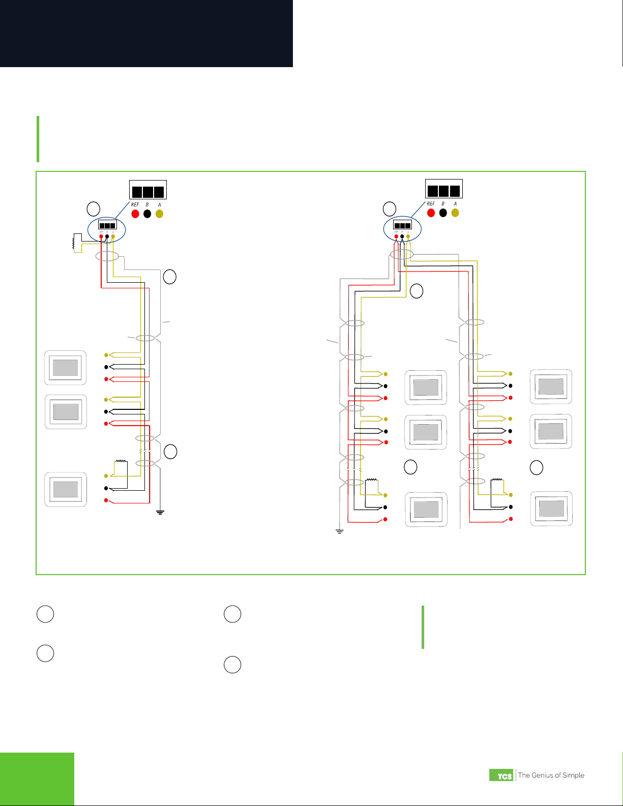
1. Verify all RS-485 connections from the controller network to the QD3041 are complete.
NOTE: Refer to “QD3041 Power and Communication Connections” on page 4 for steps 2 through 5 below.
2. Verify that all 24V power wiring to the controller network has been completed; all controllers are powered on and
each controller has been programmed with a unique BACnet MS/TP address and device ID.
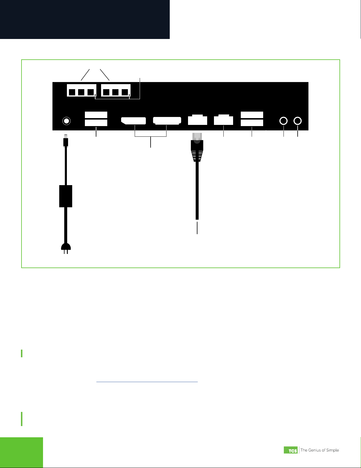
3. Connect one end of the Ethernet cable to the Ethernet port (C) on the QD3041, and the other end to the network port
provided by the customer, or to a cell modem (if utilized).
4. Connect the power source to the QD3041 and apply power. If your QD3041 shipped precongured, it will automatical-
ly go online and contact Ubiquity Cloud.
5. You MUST call TCS Technical Support (800-288-9383 ext. 2) to verify connection and activate the unit.
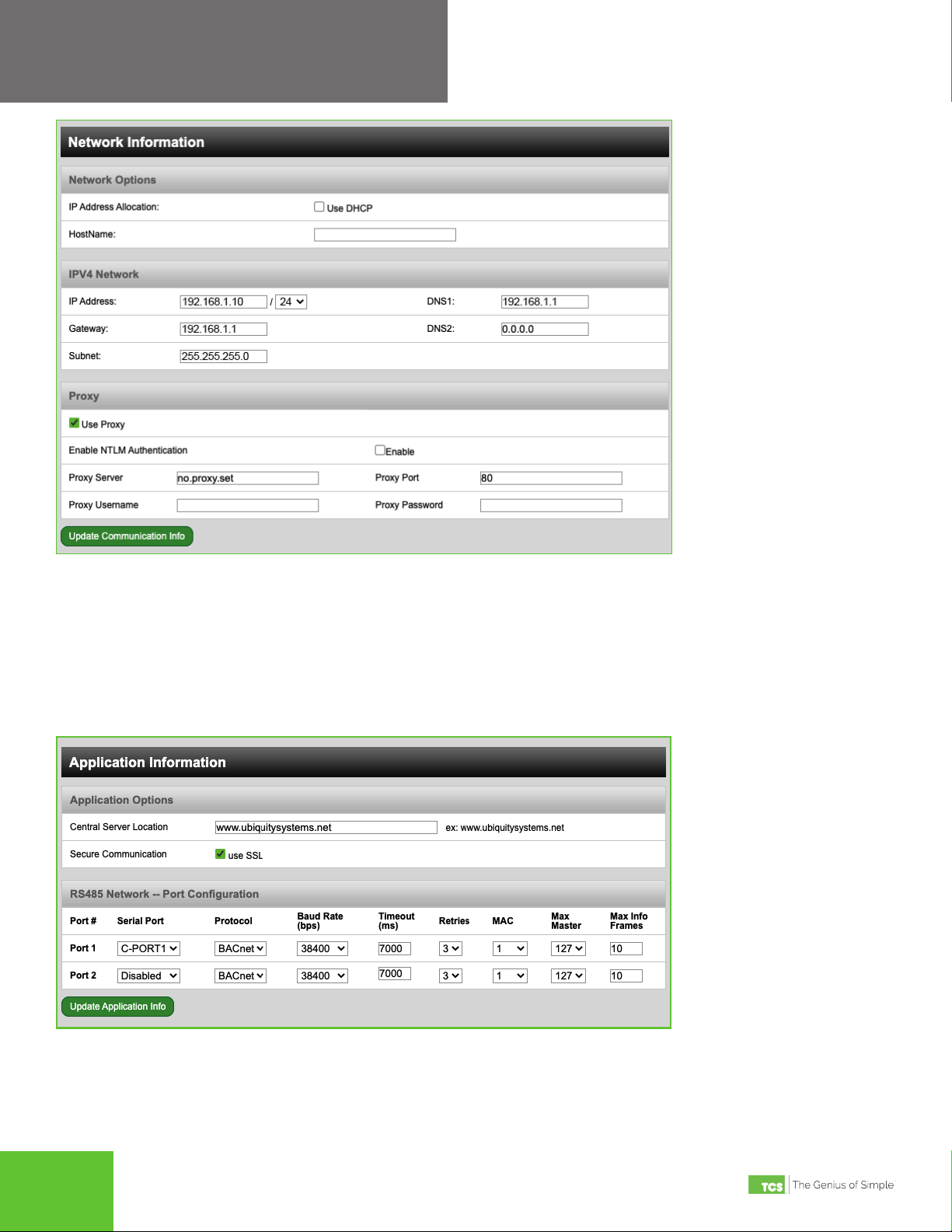
6. If your QD3041 was not ordered precongured: You can congure it at this time. See the Conguration Section on
page 8.
Troubleshooting
Power LED Does Not Light Up
Be sure that the power supply module included with the QD3041 is plugged in to a 120VAC outlet that has power and
the 12V, 5A tip positive barrrel socket is plugged into the unit. Press the power button on the front of the unit; a blue light
should come on, indicating the unit ispowereed up.
No Communications with Controllers on the Network
Make sure the baud rate selection for the QD3041 is set to match the baud rate of all the controllers on the network. All
controllers on the network must have a unique MS/TP address and BACnet Device ID. Each port must be properly cong-
ured.
Check the network wiring, making sure to follow polarity; the wire that goes to A must go to A in all devices, as well as the
wire that goes to B and REF.
No LAN Link to the Internet
Verify the network cable is connected correctly and make sure the LEDs next to the Ethernet jack are properly illuminat-
ed. For example, a solid green LED at the RJ-45 LAN connector usually indicates that the QD3041 is either connected or
receiving a signal. If the green light is ashing, this is an indication of data being sent or received.
If there are no lights, the QD3041 may not be connected properly, or may not be receiving a signal from the network. If,
after checking the connections, the LED indicators are still off, the network adapter, port, or cable may be defective.
If there are lights but there is still no communication, this could be because the network communication is not set proper-
ly or there is a bad rewall proxy setting. Contact your IT department for support, or contact TCS Technical Support (800-
288-9383, ext. 2) for assistance.

2800 Laura Lane • Middleton, WI 53562 | 800.288.9383 | www.tcsbasys.com
77
Installation
No Communication with RS-485 Ports (COM 1 and 2), Ubiquity Time-out, or No Data
Verify each port on the QD3041 has the proper biasing resistors. Verify each port is also optically isolated, which cleans
up the signal and protects the unit from taking stray voltage off the RS-485 lines.
A set of LEDs on each of the RS-485 ports in the QD3041 allow the building occupant to view operational status of the
serial communication integrated board:
• GREEN – blinking indicates transmitting (Tx)
• YELLOW – blinking indicates receiving (Rx)
If neither of these lights are functioning, there could be a bad connection, a bad cable, a bad ground, or a bad component.
This could also be a conguration issue. Contact TCS Technical Support (800-288-9383, ext. 2) for assistance.

2800 Laura Lane • Middleton, WI 53562 | 800.288.9383 | www.tcsbasys.com
89
89
ConfigurationConfiguration
Introduction
The QD3041 utilizes an internal Gateway to communicate with Ubiquity Cloud and the attached device networks. This
Gateway can be congured locally by connecting a laptop directly to the unit, or by connecting a monitor and keyboard.
When using a laptop, you can congure the Gateway through the QD3041’s internal web page. When using a monitor and
keyboard, you can congure the Gateway via the text-based Command Line Interface (CLI).
NOTE: All Ubiquity Cloud services are accessed by logging into the Ubiquity Cloud Server (www.ubiquitysystems.net),
not by using the internal web page.
The QD3041 has a default Gateway login and password, which is supplied to customers upon request. It is the custom-
er’s responsibility to congure a custom login and password. Contact TCS Technical Support (800-288-9383, ext. 2) for
information on managing login credentials.
QD3041 Conguration via Laptop
Once you have made a connection and have logged in (see “Appendix A: Local Management Port” on page 16) you can
congure the operation of the unit.
If you are unable to access the configuration page, contact TCS Technical Support (800-288-9383, ext. 2) for assistance.
Installation Information
The BACnet Device Properties section contains unit-related information used to uniquely identify the unit when it is being
serviced in the eld. It also contains software/application-related information such as the software version and patch
level.
Installation Information
IMPORTANT: If you ordered your QD3041 preconfigured, which is typical, you can skip this section!
The Configuration section is for those who need to configure or reconfigure their unit.

2800 Laura Lane • Middleton, WI 53562 | 800.288.9383 | www.tcsbasys.com
99
Configuration
Device ID: The Device ID is a BACnet address that identies the unit on the BACnet network (similar to an IP address).
This number must a unique number. Once you have assigned a unique number to the unit, click the Update Device Info
button to save the number.
The Site Time section is used by the local network and the QD3041 until the Ubiquity Cloud Server performs a time syn-
chronization with the site.
Enter the timezone information in this section and click the Update Time Info button to save the setting.
Network Information
This section contains settings which control how the QD3041 connects to the Internet. All of these settings are deter-
mined by your local network administrator or IT department.
Network Information – Use DHCP
Network Options
The QD3041 supports both static IP and Dynamic Host Conguration Protocol (DHCP) IP address allocations. When utiliz-
ing DHCP addressing, the IP address settings are automatically assigned when communication is established. Enter host
name if needed (typically left blank).
IPV4 Network
If you are using a static IP address, deselect “Use DHCP” and ll in the static IP address information (IP Address, Gateway,
Subnet, DNS1 and DNS2 settings) established by the LAN/ WAN network administrator prior to installation.

2800 Laura Lane • Middleton, WI 53562 | 800.288.9383 | www.tcsbasys.com
10 11
10 11
Configuration
Network Information – Static IP Conguration
Proxy
If a proxy is required, select the “Use Proxy” check box and enter all the related details in the elds that appear. When you
are nished entering information in this section, click the Update Communication Info button.
Application Information
This section contains settings which dene how the QD3041 interacts with the controller network, and how it communi-
cates the data to Ubiquity Cloud.
Application Information

2800 Laura Lane • Middleton, WI 53562 | 800.288.9383 | www.tcsbasys.com
1111
Configuration
Application Options
Central Server Location: Default is set to www.ubiquitysystems.net; do not change this setting.
Secure Communication: Secure Sockets Layer (SSL) Default is selected (SSL MUST be enabled and requires port 443 to
be open).
RS-485 Network - Port Conguration
The two RS-485 communication (COM) ports are congured in this section. While the QD3041 automatically detects the
active COM ports, you must adjust the settings on each active port to ensure proper functioning of the network. You can
also enable or disable either port from the drop-down menu.
Protocol: Select the communications protocol being used on each port. BACnet is selected by default and is the only
protocol available on the QD3041.
Baud Rate: This is the data transmission speed on the network. The Baud Rate must be the same selection for the port
conguration as it is on every device communicating to that port. The default baud rate is 38400. Other available baud
rates are 9600, 19200, 57600 and 115200.
Time-out Period: This is the number of milliseconds the port on the QD3041 will wait for a response from the network
devices before determining that a device is not communicating, or has “timed out.” Select the time-out period for each
port. TCS recommends 7000 ms.
MAC: This is the local MS/TP address. Default is set to 1, which may need to be changed if another device is using that address
.
Max Master: This refers to the upper limit of addresses that the unit will communicate with. This number should always
equal or exceed the highest device MS/TP address.
Max Info Frames: This setting controls how many token passing messages the device can send over MS/TP. TCS recom-
mends not changing this setting. When you are nished entering information in this section, click the Update Application
Info button.
Security Information
This section contains settings which control the security of the QD3041 and whether it can be accessed through the web
interface. This is also where you change the login credentials.
Security Information
Select Remote Access Mode: This controls the kind of remote access you will allow to the QD3041:
• Normal: (Default checked) Allows access via web browser and SSH.
• No Web Interface: Turns off access via a web browser. Device is still congurable via SSH.
• Black Box: Restricts all access. Device is only congurable via the LAN Admin port (L).
Web Interface Username/Password: Use these elds to change the username and password.
NOTE: The QD3041 has a default Gateway login and password, which is supplied to customers upon request. It is the
customer’s responsibility to congure a custom login and password. Contact TCS Technical Support (800-288-9383,
ext. 2) for information on managing login credentials.
Once you are nished entering information in this section, click the Update Security Info button.

2800 Laura Lane • Middleton, WI 53562 | 800.288.9383 | www.tcsbasys.com
12 13
12 13
Configuration
Commissioning Tools
You can access a separate page containing various commissioning tools by clicking the “Commissioning Tools” button at
the bottom of the Security Information page. These tools provide you with access to managing the communication status
of the QD3041 and the controller network connected to it.
Commissioning Tools
Ubiquity Cloud Connection Status
This section displays the status of the connection between the QD3041 and the Ubiquity Cloud Server. You have three
options for the message that will appear here:
1. Error - No Route to Host: The unit does not currently have an Ethernet connection.
2. Connected: The unit is able to communicate to the Ubiquity Cloud Server BUT is not being matched up with a spe-
cic site. Typically this indicates that the site is not initialized on the Ubiquity Cloud Server side yet. Contact TCS
Technical Support (800-288-9383, ext. 2) to assign or initialize the QD3041 to a site.
3. Established: The unit is communicating with the Ubiquity Cloud Server AND is ready to go. All Ubiquity functions
(monitoring, programming, alarming, etc.) should be available through the user interface at this point.
Clicking the Refresh button will refresh the connection status.
Refresh Button

2800 Laura Lane • Middleton, WI 53562 | 800.288.9383 | www.tcsbasys.com
1313
Configuration
Controller View
This section allows you to see what controllers have been found by the QD3041. It also shows addressing and Device ID
information, vendor information and communication status. This information allows the installer to verify that each con-
troller has been found by the QD3041 and is communicating with the local network. Clicking the green Refresh button on
the Controller View title bar will refresh each controller’s status.
System Commands
This section describes how to set up system ags for the QD3041. “Reboot Unit” sets a ag which will reboot the QD3041
within a ve-minute cycle. “Restart Application” will restart the software running on the device. “Check for Update” con-
tacts the Ubiquity Cloud Server for any updates relevant to its particular model number and software version. When an
update has been downloaded, it is automatically applied; the unit will reboot if necessary.
NOTE: The “Check for Update” command requires that the QD3041 have Internet access to retrieve the update patch.
QD3041 Conguration via Command Line Interface (CLI)
When you connect a keyboard and monitor to the QD3041 (See “Appendix C: Monitor and Keyboard” on page 25), you
can congure it for your site by using the built-in CLI.
1. To establish a connection to the CLI, you must enter a login user name and password. If you have not changed the
user name and password, you must enter the default credentials.
NOTE: If you do not have the default credentials for this unit, contact TCS Technical Support at 800-288-9383 ext. 2 for
assistance.)
2. Once logged in, type in “tcssetup.” This will open the CLI (see “Command Line Interface Screens” on page 14).
3. Type the number for the selection you want and press “Enter”.
4. Type in new values on any eld as needed. Pressing “Enter” will save the new value, or keep the current value.
5. When nished with a section, type “0” and press “Enter” to go back to the main menu.
6. After all programming is complete, navigate back to the main menu and type “8” and then press “Enter.” This will
save all changes. Typing “0” and pressing “Enter” at the main menu will exit programming without saving changes.
NOTE: After you have finished configuring the QD3041, you can revert your laptop back to its original DHCP settings, if
desired. See “Appendix B: Revert Back to DHCP Settings” on page 22.

2800 Laura Lane • Middleton, WI 53562 | 800.288.9383 | www.tcsbasys.com
14 15
14 15
Configuration
Command Line Interface Screens
Conguration Screen 1
Device ID
Network Options
Proxy Options

2800 Laura Lane • Middleton, WI 53562 | 800.288.9383 | www.tcsbasys.com
1515
Configuration
Application Options
Serial Options
Security Options
View Device Properties

2800 Laura Lane • Middleton, WI 53562 | 800.288.9383 | www.tcsbasys.com
16 17
16 17
AppendicesAppendices
Appendix A: Local Management Port
The QD3041 can be congured locally at the device using a laptop computer. If using this method of conguration, you
will need:
1. Laptop with a hardwired Network Interface Card (NIC).
2. Ethernet cable.
Connection Setup
Ethernet Cable
Connect one end of the Ethernet cable to the Local Management Ethernet Port on the QD3041 (see “QD3041 Power and
Communication Connections” on page 4) and the other end to the laptop's Ethernet port.
Laptop
The steps below require changing the network settings of the laptop; this is done at your own risk.
Windows 10:
1. Search for Ethernet Settings and click the “Open” link.
Ethernet Settings
2. On the Ethernet Settings panel and click the “Change adapter options” link.

2800 Laura Lane • Middleton, WI 53562 | 800.288.9383 | www.tcsbasys.com
1717
Appendices
Change Adapter Options
3. On the Network Connections panel locate the Ethernet interface that is connected to the cable. Right click on the
item and select “Properties.”
Properties
4. On the Ethernet Properties panel locate the “Internet Protocol Version 4 (TCP/IPv4)”. Select that option, then click on
the “Properties” button.

2800 Laura Lane • Middleton, WI 53562 | 800.288.9383 | www.tcsbasys.com
18 19
18 19
Appendices
TCP/IPv4

2800 Laura Lane • Middleton, WI 53562 | 800.288.9383 | www.tcsbasys.com
1919
Appendices
5. On the Internet Protocol Version 4 (TCP/IPv4) Properties change the IP schema to:
• IP Address: 10.248.248.2
• Subnet Mask: 255.0.0.0
• Default Gateway: 10.248.248.2
• DNS: Blank
6. Click on the “OK” button and close the window.
Port to Static Settings

2800 Laura Lane • Middleton, WI 53562 | 800.288.9383 | www.tcsbasys.com
20 21
20 21
Appendices
7. Launch any web browser and type https://10.248.248.1 in the address eld.
Device Address
8. Depending on your browser’s conguration, you may get the following screen:
Privacy Error Warning Screen
9. Click on the “Advanced” button in the Privacy Error Warning screen.
Table of contents
Other TCS Conference System manuals
Popular Conference System manuals by other brands

Furman
Furman PB-48 owner's manual

COMMUNICATIONS-APPLIED TECHNOLOGY
COMMUNICATIONS-APPLIED TECHNOLOGY ICRI-WFM Setup and operating procedures

Polycom
Polycom QDX 6000 System user guide

Sennheiser
Sennheiser TeamConnect Wireless Set Tray M user guide

Yealink
Yealink RoomCast Zoom Edition user guide

Revolabs
Revolabs FLX2 10-FLX2-200-POTS user manual