TCS AZC41000-0010 User manual

Product information
transponder reader
AZC41000-0010

2

3
Table of contents
Scope of delivery............................................................................................................ 4
Introduction.................................................................................................................... 4
Notes on this product information.................................................................................................................................4
Used symbols and warning notices ..............................................................................................................................4
Further used symbols and designations.......................................................................................................................4
Safety instructions......................................................................................................... 5
General safety regulations............................................................................................................................................5
Requirements to protect against lightning ....................................................................................................................5
Product description ....................................................................................................... 5
Intended use .................................................................................................................................................................5
Short description...........................................................................................................................................................6
Display and control elements........................................................................................................................................6
Device overview............................................................................................................................................................7
Tecnical data.................................................................................................................................................................8
Mounting and installation .............................................................................................. 8
win:clipTM-System..........................................................................................................................................................8
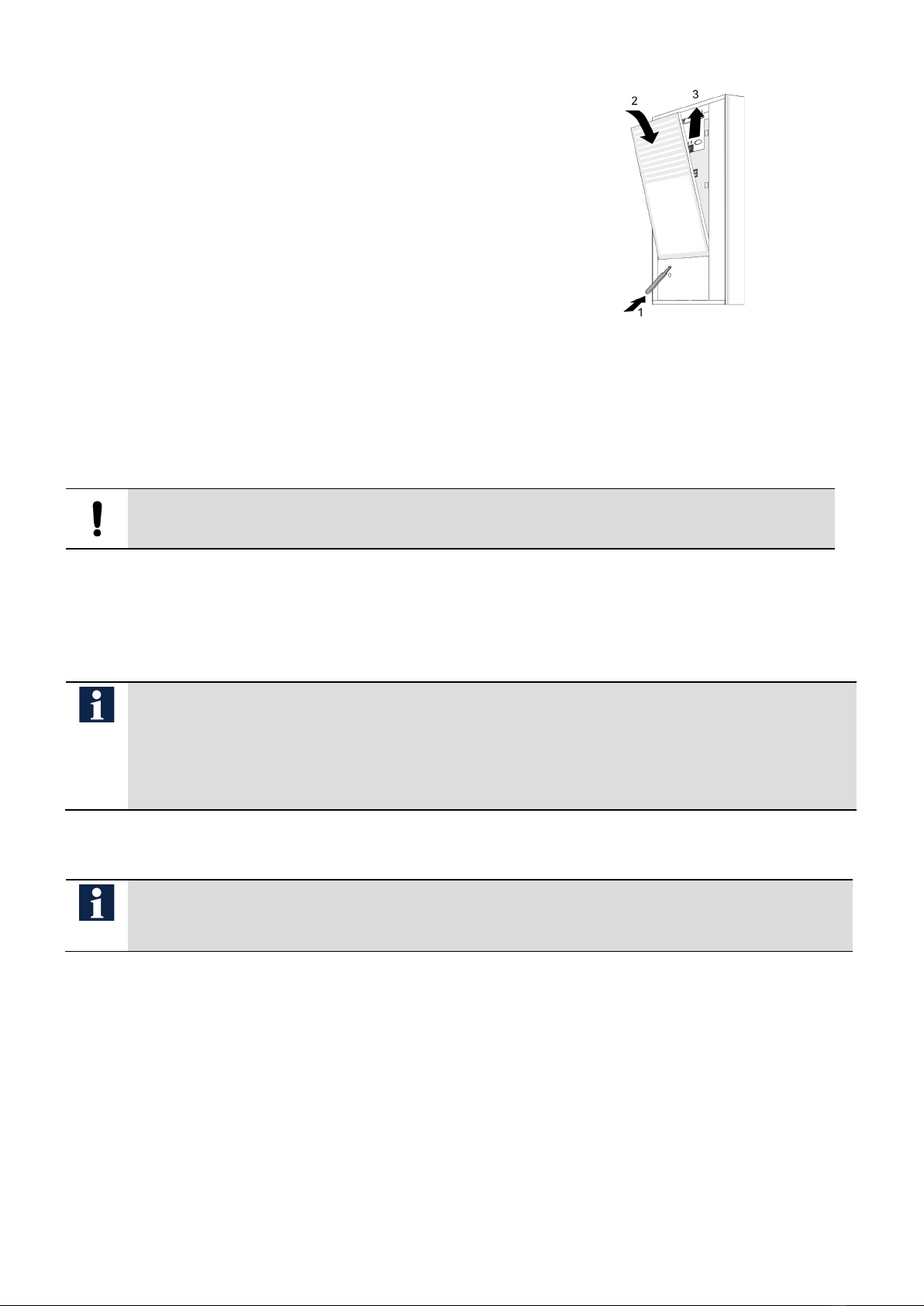
Install the front door station ..........................................................................................................................................9
Connecting the lines .....................................................................................................................................................9
Example circuit 1: TCS:BUS with VBVS05.................................................................................................................10
Example circuit 2: installation with multiple transponder readers..............................................................................10
Example circuit 3: TCS:BUS with BVS20-SG.............................................................................................................11
Door opener in mixed installation ...............................................................................................................................11
Adapting the device ..................................................................................................... 11
Adapting the device ....................................................................................................................................................11
Activate infrared remote control..................................................................................................................................12
Initial operation............................................................................................................ 12
Error detection and indication .....................................................................................................................................12
Settings .......................................................................................................................................................................12
Configuration................................................................................................................ 13
Possible configurations...............................................................................................................................................13
Initial commissioning...................................................................................................................................................14
Legend ........................................................................................................................................................................14
Notices ........................................................................................................................................................................15
Programming with infrared remote control .................................................................................................................15
Programming with master transponder ......................................................................................................................23
Label info sign.............................................................................................................. 26
Operation...................................................................................................................... 26
Infrared remote control change batteries................................................................... 27
Cleaning........................................................................................................................ 27
Conformity .................................................................................................................... 27
Information on disposal ............................................................................................... 27
Warranty ....................................................................................................................... 28
Spare parts, accessory ................................................................................................ 28
Service.......................................................................................................................... 28

4
Scope of delivery
1 x transponder reader
1 x infrared remote control
1 x win:clipTM-key
1 x screwdriver
foil for info tags, empty
product information
key list
Introduction
Notes on this product information
This product information refers exclusively to qualified electricians.
The product information contains important notes on intended use, installation and initial operation.
Please, keep the product information at a suitable place, where it is easily accessible for maintenance
and repair reasons.
All product informations are available in the download area at www.tcsag.de .
Used symbols and warning notices
Symbol
signal word
Explanation
DANGER! The signal word describes an endangering with a high level of risk. Failure to observe
this warning will result in death or very serious injury.
WARNING! The signal word describes an endangering with a medium level of risk. Failure to ob-
serve this warning could result in death or very serious injury.
CAUTION! The signal word describes an endangering with a low level of risk. Failure to observe
this warning could result in a minor or moderate injury.
ATTEN-
TION!
The signal word indicates that damage to equipment, environment and property can
occur.
Further used symbols and designations
important note or important information
►
Step
cross reference for further information on this topic, see source
•
list, list entry 1 level
–
list, list entry 2 level
a)
Explanation

5
Safety instructions
General safety regulations
Assembly, installation, commissioning and repair of electronic devices must be carried out by
qualified electricians.
Observe the latest regulations and standards for system installations.
WARNING!
Danger to life due to electric shock
Observe the safety regulations according to DIN VDE 0100, when working on main power
connections of 230 V.
When installing TCS:BUS systems, the general safety regulations for telecommunication sys-
tems according to VDE 0800 must be observed. Inter alia:
•separated cable routing of high and low voltage lines,
•minimum distance of 10 cm in case of a common cable routing,
•use of separators between high and low voltage lines within shared cable ducts,
•use of standard telecommunication lines, e.g. J-Y (St) Y with 0.8 mm diameter,
•already existing lines (modernization) with deviating cross-sections can be used in compli-
ance with the loop resistance.
Requirements to protect against lightning
CAUTION!
Device damage due to over-voltage
By suitable lightning protection measures it has to be ensured that the electric voltage of 32 V
DC at each connection is not to be exceeded.
Product description
Intended use
The transponder reader is a transponder unit to read transponder keys and cards* without contact. It is a
surface-mounted system, which can be used both indoors and outdoors.
If the installation recognizes the key, it sends a door opener protocol or a freely configurable protocol
and the internal relay is activated. In combination with the power supply and control unit BVS20-SG, it
can be used as a stand-alone system.
The transponder reader can be combined with all TCS:BUS audio and video kits. It can be integrated
into large bus installations with up to 64 external units.
* MIFARE Classic® is a registered trademark of NXP B.V.
For applications, which differ from the intended use or goes beyond it, the manufacturer ac-
cepts no liability.

6
Short description
•Transponder (Mkey, MCard) with MIFARE Classic® 1K / 4K technology
•shatter-proof nameplate glass
•Configuration with configuration software configoTM
•Configuration with infrared remote control (included)
•Password protection against unauthorized configuration
•Key confirmation tone when pressing the infrared remote control
•Setting a master transponder via infrared remote control or with configoTM
•Programming of MIFARE Classic® compatible transponder
– up to 10 per master transponder
– up to 50 per infrared remote control
– up to 250 TCS:BUS installations possible using configoTM
•Visual and acoustic notification when reading the key
•Visual and acoustic error indication
•Operation with 2/3 wires can be switched
•RS485 interface
•Maximum line resistance: 20 or 60 Ω / can be activated
•Door opener function with potential-free relay contact (two-way switch: 24 V DC / 2 A)
•Adjustable door opening time, factory settings at 3 seconds
•Sabotage contact
•Update possible via ISP interface
The device is based on another technology such as the transponder-readers tLeser-GH and
tPAKL-EN. Transponder of types tKey01 and tCard01 cannot be used.
Display and control elements
LED green
•On (3 s): transponder card recognized, access granted
•Blinks slowly: programming in programming mode is possible using infrared
remote control or master transponder
LED red
•On (3 s): transponder card is not recognized
•On (2 min.): blocking time after master code has been entered incorrectly 3 x
using infrared remote control or wrong master transponder was used 3 x, wrong
transponder was used 3 x
•blinks slowly: possible to delete in the programming mode via master tran-
sponder
LED
orange
•On: manual programming mode via master transponder, all memory locations
are assigned
•blinks: manual programming mode via master transponder, one memory loca-
tion still available
•flashes: error indication

7
Device overview
Fig. 1: AZC41000, nameplate partially visible
1
attachment hole 1, 2
7
flush panel
2
cable gland
8
LED (green / red / orange)
3
DIP-switch
9
opening for win:clipTM-key
4
sabotage contact
10
nameplate glass
5
attachment hole 3
11
IR receiver
6
print card
12
connection terminal

8
Tecnical data
supply voltage
+24 V ± 8 % (power supply and control unit)
18 bis 28 V (for stand-alone mode)
input current in resting position
3-wire operation:
I(a) = 0,1 mA, I(P) = 17 mA
maximum input current I(Pmax) = 40 mA
degree of protection IP44
acceptable ambient temperature -25°C ... +55°C
housing
aluminum, anodized nature
dimensions (mm)
H 153 x B 104 x T 16
weight
340 g
RFID-Technology
MIFARE Classic®, carrier 13,56 MHz
relay contact
change-over, 24 V AC / DC / 2 A
Infrared remote control
carrier frequency
37,9 KHz ± 125 Hz
signal range
at least 1 m in open spaces (15 ° deviation from direction
at a distance of 3 m)
operating temperature
-10 to +50 °C,
storage temperature
-20 to +60 °C
remote control batteries
button cell battery CR2025 (DC3.0 V)
Mounting and installation
win:clipTM-System
The device is equipment with the win:clipTM system to open and close the station without using any
screws.
Open the housing
►Push the enclosed win:clip key into the small opening within
the loudspeaker cover.
►Press the key into the opening until stop and keep it in this
position.
►Push the name plate glass slightly upwards until it jumps
out.
►Put out the glass carefully.
►Remove the plug of the name plate illumination.
►Remove the win:clip key.
Fig. 2: win:clip
TM
, open

9
Close the housing
►Connect the plug of the name plate illumination (see instal-
lation).
►Push the enclosed win:clip key into the small opening within
the loudspeaker cover.
►Press the key into the opening until stop and keep it in this
position.
►Push the name plate glass under the loudspeaker
cover.
►Press the name plate glass onto the device. Push it slightly
downwards until it snaps-in.
►Remove the win:clip key.
Fig. 3: win:clip
TM
, close
Install the front door station
►Open the device (see win:clip system)
►Perforate carefully the foam cover on the backside of the device.
ATTENTION!
Damage to the connection wires.
Ensure that the cables from the rear panel do not get clamped.
►Mount the device via the mounting holes onto the wall using suitable screws.
Connecting the lines
Connecting lines
Allowed cross-section (diameter): 0,08 ... 1 mm2(Ø 0.3 ... 1.4 mm)
Max. number of wires per terminal contact: 2 x 0.8 mm or 3 x 0.6 mm
Connect further wires by using auxiliary terminals.
Use only connecting lines made of the same material and with the same diameter within one
terminal contact.
General information
•Use the small slot screwdriver (enclosed in the delivery) to connect the lines. Avoid damag-
ing the device.
•The internal resistance of the door opener shall not exceed 6 Ω.

10
Example circuit 1: TCS:BUS with VBVS05
Fig. 4: example circuit 1
Example circuit 2: installation with multiple transponder readers
Fig. 5: example circuit, door opener with separate power supply
door
opener
door
opener
door
opener
door opener
light

11
Example circuit 3: TCS:BUS with BVS20-SG
Fig. 6: example circuit 3
Door opener in mixed installation
If, in addition to the AZC41000, there are also audio and/or video front-door stations installed,
the function “Switch door release relay with door release protocol” must be activated using
configoTM (is already activated in the delivery state). The same AS-address must be assigned
to the AZC41000 as to the front-door station of the associated door. It is not necessary to con-
nect an FAA11000 or FAA1200 door release relay to the audio/video front-door station.
Adapting the device
Adapting the device
The transponder reader is factory set for systems with loop resistance of ≤ 20 Ohm and operation on the
TCS:BUS (3-wire technique). The adjustment is made at a DIP switch which is secured with a plastic
plate. See device overview, p. 7.
Only remove the self-adhesive plastic plate on the DIP switch if you need to make an adjust-
ment.
Adjust systems without P-wire (2-wire operation)
Requirement: Only one reader can be connected per
power supply and control unit.
For new installations, a P-wire must be provided.
►Remove the plastic plate.
►Set switch 1 to ON if there are only two lines in a system.
Switch 1
2-wire technique
3-wire technique a)
Fig. 7: DIP-switch 1
a) factory preset
door opener
light

12
Adjust length of lines in systems (long lines)
a) factory preset
Activate infrared remote control
►Remove the battery cover on the back of the infrared remote control.
►Remove the foil strips.
►Replace the battery cover.
Initial operation
►Install the devices of the system completely.
►Proof the a-, b- and P-wire against each other on short-circuits.
►Switch on the mains voltage.
Error detection and indication
Errors are signaled acoustically and optically: one error tone and constant flashing of the operation indi-
cation.
The optical error indication stays active until the error is fixed.
error cause
indication
error mode
error tone solution
a- and P-wire interchanged or
short circuited
LED
flashes
orange
change a- and P-wire or remove short-circuit, de-
vice goes into stand-by mode again
a-wire: not connected or not
supplied
connect a-wire or check power supply, device
goes into stand-by mode again
Sabotage contact activated:
control function 199 with own
serial number for “silent alarm”
is sent
insert nameplate correctly
Settings
Sabotage contact
When the sabotage contact is activated, a protocol is sent and an error message is displayed (LED
flashes orange). A control function with its own serial number is sent. If the device is properly closed
again, full functionality is restored.
► Configure the control function number using the configuration software configo™.
Requirement: Front-door stations and power supply
and control units connected to the system, must be
suitable for systems with a loop resistance of up to 60
Ohm.
►Remove the plastic plate.
►Set switch 2 to ON, in order to use a line resistance Zs up to 60
Ohm.
switch 2
lines
long (Zs≤60 Ohm)
normal (Zs≤20 Ohm) a)
Fig. 8: DIP-switch 2

13
Factory settings
The device is equipped with an EEPROM in which the following device settings are stored at the factory:
AS-address for door opening function
0
switching time for relay contact
approx 3 s
programming lock OFF (= 0)
switch relay contact on receipt of a door opener protocol
ON (= 1)
Programming mode can only be switched on at the power supply and
control unit
ON (= 1)
acoustic signaling AN (= 1)
free protocols 1 to 4
00000000 (16 bit)
Master code
Serial number of the device
Master transponder code 00000000 (no master transponder)
TCS:BUS connected
YES
Sabotage contact activated
ON (= 1)
control function in case of sabotage 199
Configuration
Possible configurations
Function
Infrared remote control
Master transponder
configoTM
train transponder
x
(limited to 50)
x
(limited to 10)
x
(limited to 250)
delete transponder
x
(delete individually)
number memory address
must be known
- x
x
(delete simultaneously)
x
(delete simultaneously)
x
set AS-address x - x
set relay switching time x - x
load factory setting
x
-
x
train master transponder
x
-
x
change master code x - x
set programming lock - - x
stand-alone operation
-
-
x
free protocols 1 to 4
-
-
x
control function sabotage - - x

14
Initial commissioning
with infrared remote control
see page 15
with configuration software configoTM
analog see page 15
with user program access control (PCiACC)
see manual PCitACC
with service device TCSK
no programming possible
Legend
Acknowledgement tones
tone symbol meaning
short acknowledgement tone
•Infrared remote control confirms pressing the button with a
short button acknowledgement tone.
positive acknowledgement tone
•Correct entry or correct operation.
negative acknowledgement tone
•Wrong entry or wrong operation.
Legend LED indication
LED status symbol meaning
green
ON (for 3 s)
•Transponder card recognized, access granted.
flashes
•ready for programming in programming mode via infrared remote
control or master transponder
red
ON (for 3 s)
•Transponder card not recognized
ON (for 2 min)
lock wait after:
•triple entry of an incorrect master code via infrared remote control
•triple use of an incorrect master transponder
•triple use of an incorrect transponder
flashes
•delete readiness in programing mode via master transponder
orange
ON
•manual programming mode via master transponder
•all memory addresses are occupied
flashes
•manual programming mode via master transponder
•only one free memory
blinks
•error indication when commissioning
Run/
Prog-
button
ON
•Programming mode of the system is switched OFF.
blinks
•Programming mode of the system is switched ON.

15
Notices
•For programming you need the 6-digit serial number of the transponder reader.
•A transponder contains a unique number that can be assigned to one or more transponder readers.
This number is stored in the transponder reader.
•A transponder (or master transponder) can be allocated to several devices.
•If the entry is correct, a positive acknowledgement tone ( ) sounds.
If the entry of a command sequence … is interrupted for 8 s, the entire command se-
quence is rejected and a negative acknowledgement tone ( ) sounds.
•If the command sequence does not correspond to the specified syntax or if too many parameters
have been entered, the entire command sequence is also rejected and a negative acknowledgement
tone sounds.
•When operating the infrared remote control, always aim the head of the remote control directly at the
front-door station. The range of the infrared remote control is max. 1 m in direct distance.
•Each press of a button on the infrared remote control is confirmed by the transponder reader with a
short acknowledgement tone ( ).
For safety reasons, the master code set ex works should be changed.
Programming with infrared remote control
Keep the device closed during programming to prevent programming errors due to an open
sabotage contact.
In order to program the device with the infrared remote control, you need the infrared remote control in-
cluded in the scope of delivery.
Pressing a key at the remote control is confirmed with a short key acknowledgement tone .

16
Initiate programming
Power supply and con-
trol unit: put tran-
sponder reader in pro-
gramming mode
Switch ON and OFF
the programming
mode of the system
►Shortly press RUN/PROG Button, LED
blinks. You now have 5 min. to pro-
gram.
►Shortly press RUN/PROG Button, LED
is ON.
Authorize via infrared
remote control
Enter master code
Device ready for pro-
gramming
Wrong entry, unknown
master code
No entry
...
Pressing a button is confirmed by the
device with a short button
acknowledgement tone.
►master code (WE*: 6-digit serial num-
ber of the transponder reader)
►
*WE= factory setting
a positive acknowledgement tone sounds,
LED lights green for 3 s,
LED blinks green.
A negative acknowledgement tone sounds
when pressing the #-key.
LED lights red for 3 s,
LED lights green again.
The code entry is blocked for 2 min
after the code has been entered
wrong 3 times.
LED lights red for 2 min., then blinks green
again.
►Then start again.
If after 2 min. no command has been en-
tered, the device will automatically terminate
the programming mode.
The LED switches off.

17
Train transponder
Initiate program-
ming
If not yet done
Enter command
Present transponder
Transponder is trained
Train further tran-
sponders
Only 1 memory address
is free.
All 50 memory addresses
are occupied
Transponder is rejected:
•memory is occupied
•transponder has al-
ready been trained on
another memory ad-
dress
…
►* 0 # SpNr #
SpNr = memory location 0 to 49
►Hold the transponder in front the de-
vice
a positive acknowledgement tone sounds,
LED lights green for 3 s,
LED blinks green again.
►Repeat the steps below.
LED blinks orange.
LED lights orange.
A negative acknowledgement tone sounds
when the transponder is held in front of the
device,
LED lights red for 3 s,
LED lights green again.
►Delete the occupied memory address!
►Or delete the transponder which has
been trained on the wrong memory
address!
Number of transponder which can be trained: max. 50.

18
Delete a transponder
Initiate program-
ming
If not yet done
Enter command
delete occupied memory
Occupied memory has
been deleted
Memory is not occupied
…
►* 3 # SpNr #
SpNr = memory location 0 to 49
a positive acknowledgement tone sounds,
LED lights green for 3 s,
LED blinks green again.
a negative acknowledgement tone sounds,
LED lights red for 3 s,
LED blinks green again.
Delete all transponders
Initiate program-
ming
If not yet done
Enter command
All transponders are
deleted
…
►* 94 # Mastercode # Mastercode #
Mastercode = 6-digit number
a positive acknowledgement tone sounds,
LED lights green for 3 s,
LED blinks green again.
Number of transponder which can be deleted: max. 50.

19
Set switching time for R-terminal
Initiate program-
ming
If not yet done
Enter command
switching time is set
incorrect value has
been entered
…
►* 8 # SpNr #
SpNr = memory location 0 to 49
value = switching time adjustable in 1
s-steps, 0 to 255 s
0 = deactivated, no response
(WE = 3 s)
a positive acknowledgement tone sounds,
LED lights green for 3 s,
LED blinks green again.,
a negative acknowledgement tone sounds,
LED lights red for 3 s,
LED blinks green again.
Set AS-address
Initiate program-
ming
If not yet done
Enter command
AS-address is set
incorrect value has been
entered
…
►* 4 # Wert #
AS-address = 0 bis 63
(WE = 0)
a positive acknowledgement tone sounds,
LED lights green for 3 s,
LED blinks green again.
a negative acknowledgement tone sounds,
LED lights red for 3 s,
LED blinks green again.

20
Define a transponder as master transponder
Initiate program-
ming
If not yet done
Enter command
8 seconds
Present transponder
Master transponder is
saved
time is exceeded: tran-
sponder is rejected
►* 97 #
It must not pass more than 8 s until
presenting the transponder!
►
Shortly hold any transponder in front of
the nameplate glass.
a positive acknowledgement tone sounds,
LED lights green for 3 s,
LED blinks green again.
a negative acknowledgement tone sounds,
LED lights red for 3 s,
LED blinks green again.
When training another transponder as master transponder, the previously trained one
will be overwritten.
We recommend marking the master transponder afterwards.
Table of contents