TCW IBBS-12v-2ah User manual

REV 2.3 © 2012 TCW Technologies, LLC.
1
Integrated Back-up Battery System
Model: IBBS-12v-2ah
The Integrated Back-up Battery System, is an electronic system that combines a
Ni mh battery pack, a charger and switching logic in one convenient package. The
back up battery system has been engineered for use as a source of back up power
for single instrument applications. This unit may also be used to provide back up
power for electronic ignition systems utilized on 4 cylinder and smaller applications.
Integral to the IBBS is a nickel metal hydride battery pack and a matched charging
system to ensure the battery is properly charged and maintained. The system also
includes switching circuitry to provide a stable source of output power during normal
and emergency operations. The IBBS system also provides an output signal to
communicate the operating state of the back up bus as well as the state of the
battery.
The IBBS system connects to the standard aircraft power bus and provides an
output directly to the avionics requiring back up power. The IBBS has a pass through
power feature allowing it to provide normal as well as back up power to connected
equipment. Additionally, the IBBS system provides surge and sag protection for
connected equipment, allowing operation of critical equipment during engine starting.
No other uses of the IBBS system are permitted except for those identified in this
installation manual.
IBBS must be installed using the current aircraft standards and practices as shown
in AC 43.13 2A/1B. The installer/builder is solely responsible for determining the
suitability of the installation and use of this product.

REV 2.3 © 2012 TCW Technologies, LLC.
2
Installation Instructions:
1. IMPORTANT NOTE:
Consult the attached wiring diagrams to identify wiring connections for your
particular installation. The IBBS system may be fed from a bus that remains active
during engine starting, such as the master bus or it may be fed from an avionics
bus that is switched off during engine starting. If you want your avionics to be up
and running during engine cranking, ensure input power is derived from the master
bus.
2. The IBBS 12v 2ah was designed to drive one piece of equipment, such as an EFIS,
Autopilot or an electronics ignition module. The output current limit for this model is
3 amps maximum continuous current. If more load current is required use model
IBBS 12v 4ah. Consult the install manual for detailed specifications.
3. Mount the IBBS in a suitable location in the aircraft. Ensure the mounting points and
fasteners are suitable for the weight of the product, consult the specifications for
details. The IBBS must be mounted inside the aircraft, do not mount the IBBS in the
firewall forward area. Avoid mounting the IBBS unit up under the instrument panel
where significant heat may be trapped. Select an area that is accessible to allow for
future battery servicing. The operating temperature range of the system is 10 C° to
60 C° and the effective charging temperature range is 0 C° to 40 C°. Select an
installation location that will comply with these requirements.
4. Connect the aircraft wiring according to one of the wiring diagrams shown.
The IBBS must be powered through a properly sized circuit breaker or fuse.
ENSURE the proper size wire is utilized for the input feed, output supply and ground
connection. The IBBS has two power inputs, pin1 provides main recharge current
and main bus sensing, pin 6 provides pass through power from the main bus to the
connected load during normal operation. Connect the two input wires together at the
fuse or circuit breaker as shown in the diagrams. The IBBS 12v 2ah has three
output pins, pin 7,8,9, that provide power to the connected load. These three wires
may be paralleled together for added redundancy. The output wires of the IBBS
system are internally protected with a single 8 amp, 5 x 20 mm fuse. No additional
external fusing is required; however, use at least 20 awg wire for the output wires.
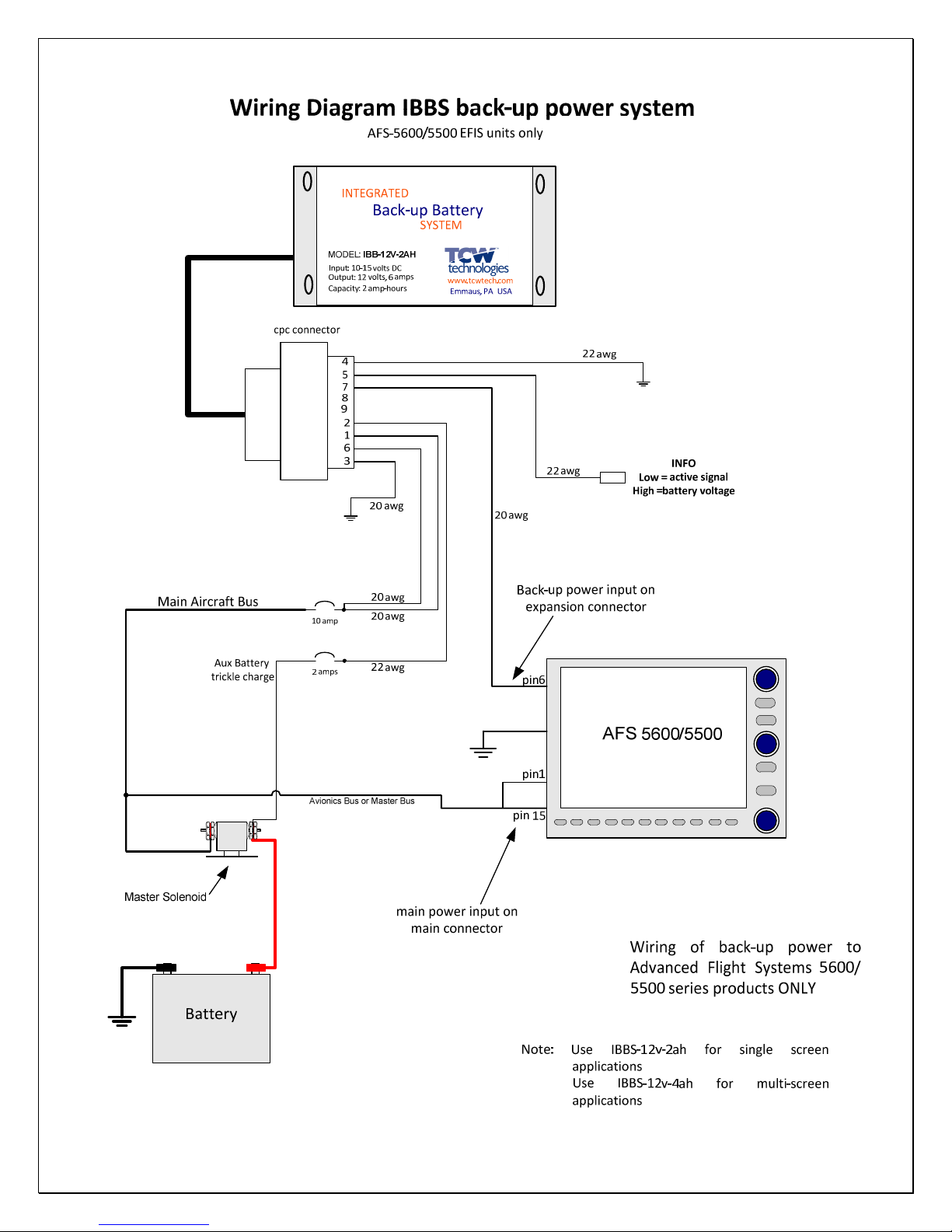
5. The Back up Power Master switch must be utilized to turn the back up battery
system off when not in use, except for installations utilizing ASF EFIS systems and
following the specific wiring diagram for this application. This switch gives the pilot
the ability to turn the back up battery system off. In some installations this may be
the only means to shut down the connected equipment.
6. Complete the installation of the wiring harness and connector prior to attaching the
connector to the IBBS product. This is essential to ensure the wires do not
inadvertently short together during installation. Remember, the IBBS pack is a

REV 2.3 © 2012 TCW Technologies, LLC.
3
back up source of power and is ready to deliver output power even when the aircraft
electrical system is in the off state.
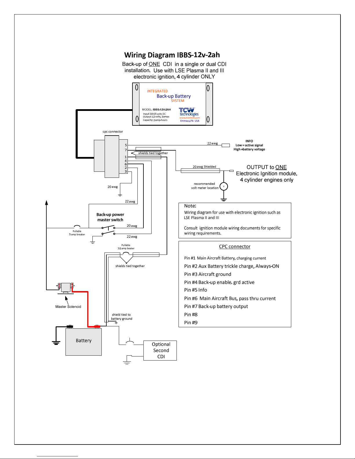
7. When using the IBBS product to provide back up power to an electronic ignition
system it MUST be used to back up one and only one electronic ignition module. Do
not use one IBBS to back up both electronic ignition modules in a dual electronic
ignition system. Follow the wiring diagram for installation with electronic ignition
module; Note, the system connections directly to aircraft battery must be utilized as
shown.
8. When using the IBBS product to provide back up power to an electronic ignition
system (CDI), pullable circuit breakers must be used for over current protection as
shown on page 17.
9. When using the IBBS product to provide back up power to an electronic ignition
system, connect one and only one CDI module to an IBBS unit. DO NOT
CONNECT any other loads to the IBBS. It must only be used to back up the CDI
unit. Follow the wiring diagram on page 17 exactly.
10. The trickle charge wire must be connected as shown in the wiring diagram. This
connection keeps the battery topped off when the aircraft remains unused for
extended periods of time.

REV 2.3 © 2012 TCW Technologies, LLC.
4
Product Details and General Information:
Back-up Po er Master S itch:
The IBBS has one input switch connection as identified in the wiring diagrams: Back up
Power Master. This switch enables back up power from the IBBS system to be
available on the output wires when power on the normal aircraft bus falls into the range
of 10 11 volts.
If the back up power master switch is “ON” and normal aircraft power falls into the
range of 10 11 volts, then the internal back up battery will be connected to the output
and be utilized to supply back up power to the connected load.
If the normal aircraft power bus is above 11 volts, then the outputs are energized with
normal aircraft power and the back up battery remains off line. This pass through
power operation occurs regardless of the state of the Back up Power Master switch.
Having the Back up Master Switch ON allows for automatic transfer of power during the
transition between normal operation and back up operation.
The “Info ire”:
The IBBS includes an “info” wire as shown in the wiring diagram. The “info” wire may
be used in conjunction with other equipment such as EFIS systems or engine monitors
to provide information regarding the state of the back up battery system. When the
IBBS is off line and normal aircraft power is available on the input of the IBBS, the “info”
line may be read to determine the internal battery voltage. A nominal battery with a full
charge will read between 12 and 15 volts. When the IBBS is on line providing back up
power, the “info” line is pulled to a logic low level to signal connected equipment that the
system is currently running on back up power.
Alternately, the “info” wire may be connected to a warning lamp to indicate that the main
aircraft bus is low and the back up bus should be switched on. See wiring diagrams for
LED warning lamp usage.
The Charging System:
The IBBS automatically maintains its internal battery pack. The internal charging circuit
monitors the state of the internal battery and recharges it as necessary when the aircraft
is operational. The maximum input current for battery recharging is 1.8 amps. When
the aircraft power bus is in the off state, a maintenance current of up to 4 milliamps may
be drawn from the aircraft battery to ensure the back up battery remains charged. The
maintenance charge current is drawn from the input wire marked: Aux Battery Trickle
Charge. If the internal battery is fully discharged for any reason it may require up to
two hours of recharge time with the normal aircraft bus on. NOTE: Do not attempt to
recharge the IBBS product by using an external battery charger directly connected to
the input of the IBBS. Battery chargers typically provide pulsating voltages that will
damage the IBBS product if the system is not connected to a typical primary aircraft
battery.

REV 2.3 © 2012 TCW Technologies, LLC.
5
Ground Based Recharging:
To accomplish ground based charging, connect an approved battery charger or power
source to the main aircraft battery and energize the main aircraft power bus by turning
on the master switch, leave all other aircraft loads in their off state. Note, the ground
base source of power must be able to supply the load current of all devices that can not
be turned off in this nominal state, plus the 1.8 amps of IBBS recharge current. Leave
the ground based charging system connected and powered until the IBBS system
completes its recharge cycle of its internal battery, for a fully discharged battery this
may take up to two hours.
Alternately, a ground based charger is available from TCW Technologies LLC, model #
IBBS 12v CHARGER. This charger may be used for recharging the IBBS unit as well
as keeping it topped off during long term product storage. (3 months or longer)
Battery Capacity:
The IBBS, model IBBS 12v 2ah provides an energy capacity of 2.0 amp hours at 12
volts when the system is fully charged and operated at 25 C°. Depending on various
conditions including operating and storage temperature and age of the battery pack, the
capacity of the system will vary. With a fully charged battery, the following average
performance can be expected in terms of operating duration. The operating duration is
for output voltage down to 9.5 volts.
Nominal Current Draw Duration
total connected load
1.5 amps 60 minutes
1.0 amps 100 minutes
0.75 amps 160 minutes
The Ni mh battery in the IBBS system is replaceable, however, the IBBS product must
be returned to TCW Technologies, LLC. for this service. Battery life depends strongly
on many factors including operating and storage temperature, number of discharge
cycles and depth of discharge. The battery capacity should be checked at least
annually for suitable back up power operation of the connected equipment. When the
battery capacity no longer meets the operating criteria of the aircraft it must be replaced.
Contact TCW Technologies, LLC. for battery replacement.
Storage beyond 3 months:
If the IBBS unit is to be stored without connection to the aircraft for a period greater than
3 months it must be connected to a source of DC power to maintain the battery’s
charge. Only connections to the ground terminal and the trickle charge terminal are
required. Connect Pin 2 (trickle charge) and Pin 3 (ground) of the IBBS to any source
of regulated DC power at 12 15 volts with a current capability of 0.1 amps to accomplish
trickle charging. The trickle charge connection may be left connected during the
entire storage period. Charger model IBBS 12v CHARGER is available from TCW

REV 2.3 © 2012 TCW Technologies, LLC.
6
Technologies, LLC. to simplify this requirement, it has the mating connector installed
and performs trickle charging as well as fast charging functions.
Upon completion of installation:
1) The builder/operator is responsible for determining the minimum operating duration
of the back up enabled equipment.
2) The required back up operating time for the connected equipment should be
recorded in the aircraft log book with follow up entries confirming the annual testing
results that indicate that the required operating time is satisfied.
Normal Product Operation:
For normal operation the following is the recommend operating procedure, it is strongly
recommended that this operating procedure be added to the aircraft operating check list
for standard procedures.
Start-up Procedure:
1) Prior to turning on the Aircraft Master Switch, turn ON the Back up Power master
switch.
2) Turn on any equipment that derives back up power from the IBBS product.
3) Ensure the connected equipment successfully boots up and is operating properly.
(During this period of time the equipment is running off of the back up battery in the
IBBS product. This test ensures the transfer circuit and back up battery are properly
working)
4) Turn on the Aircraft Master Switch, ensure the connected equipment remains
energized.
5) Start and operate the aircraft according to normal operating procedures.
Shut-do n Procedure:
1) Shut down aircraft engine using normal procedures.
2) Shut down the Aircraft Master Switch
3) Verify that equipment that derives back up power from the IBBS product remains ON
4) Turn off Back up Power Master switch, ensure that connected equipment powers
down.
(This procedure further ensures the operation of the transfer circuit in the IBBS
product.)

REV 2.3 © 2012 TCW Technologies, LLC.
7
Emergency Procedure for loss of main aircraft electrical po er:
1) Operate the Aircraft Master Power Switch per the Emergency Procedure checklist
already established for the aircraft.
2) Ensure the Back up Master Switch is in the ON position.
3) Land aircraft as soon as practical to resolve the loss of main electrical power.
Requirements for continued air orthiness:
On at least an annual basis the endurance capability of the IBBS system shall be confirmed and
compared against the back up endurance required for the connected equipment.
As an alternate to these tests, the IBBS unit may be returned to TCW Technologies for
a loaded endurance test, contact TCW Technologies for details.
Procedure for endurance testing (all applications except electronic ignition
systems):
1) Turn off the Aircraft Master Switch
2) Turn on the Back up Power Master Switch
3) Turn on all equipment connected to and supplied with back up power from the IBBS
product.
4) Measure and record at least the following information: The time until the first piece of
connected equipment no longer functions or the time until the output of back up
power supply voltage drops to 9.5 volts. AVOID allowing the back up battery voltage
to fall below 9 volts. Allowing the voltage to fall below 9 volts is detrimental to the life
and performance of the battery pack.
5) After completing the endurance test, recharge the IBBS product by operating the
system with the Aircraft Master Switch in the ON position for up to two hours. This
may done by operating the aircraft in conditions known to not require back up power
or by powering the aircraft system on a suitable ground power source as described
in the section: Ground Base Recharging.
6) Record the results of the endurance testing in the aircraft log book.
7) If the IBBS no longer meets the endurance testing requirement, the back up battery
may need replacement.

REV 2.3 © 2012 TCW Technologies, LLC.
8
Requirements for continued air orthiness: Electronic Ignition System Back-up
On at least an annual basis the endurance capability of the IBBS system shall be confirmed and
compared against the back up endurance required for the connected equipment.
As an alternate to these tests the IBBS unit may be returned to TCW Technologies for a
loaded endurance test, contact TCW for details.
Procedure for endurance testing of system providing back-up po er
to electronic ignition systems:
COMPLETE THESE STEPS IN ORDER! Perform these tests with the aircraft properly
secured on the ground, these are not flight test procedures.
1) Start the aircraft using normal starting procedures, including turning ON the Back up
Master switch
2) Select engine operation based on the use of only the electronic ignition module
provided with back up battery power.
3) PULL the 5 amp breaker feeding the Back up Master Switch, confirm engine
continues to run.
4) PULL the 7.5 amp breaker feeding pin 6 of the IBBS, confirm the engine continues to
run.
5) Perform the following; test A or test B:
Test A: abbreviated battery test:
Monitor engine operation and voltmeter reading on any of Pin 7,8,9, back up output
wires. Confirm back up voltage begins above 12.0 volts and for a period of 15
minutes remains above 11.0 volts. If these requirements are met the battery pack is
satisfactory.
Test B: full endurance test:
Operate the engine on the electronic ignition system for the required minimum run
time requirement (typically 60 minutes ) monitor the back up battery voltage on the
voltmeter connected to pin 7, the battery voltage must remain above 10 volts for the
duration of the test. If this requirement is met the battery pack is satisfactory.

REV 2.3 © 2012 TCW Technologies, LLC.
9
6) Turn off the Back up Master Switch and confirm that the engine turns off.
7) IF all these tests pass, the IBBS system is functioning properly, record the results in
the aircraft log book.
8) IF any of these tests fail, the IBBS system is not functioning properly and corrective
action must take place. If the IBBS no longer meets the endurance testing
requirement, the back up battery may need replacement.
9) Return all pullable breakers to the normal ON position and ensure aircraft engine is
properly returned to the off position by following normal run and shut down procedures.
10) After completing these tests, recharge the IBBS product by operating the system
normally for up to two hours. This may be done by operating the aircraft in conditions
known to not require back up power or by powering the aircraft system on a suitable
ground power source as described in the section: Ground Base Recharging.
For service or if you have questions, please contact us.
610 928 3420
www.tcwtech.com
email: suppo[email protected]
TCW Technologies, LLC.
2955 Main Road East
Emmaus, PA 18049

REV 2.3 © 2012 TCW Technologies, LLC.
10
SPECIFICATIONS:
Input Voltage: 10-15 volts DC
Input Current 4.8 amps max continuous
Output Voltage: 10-12 volts DC during back-up operation
Output Current: 3 amps continuous
Battery:
Internal sealed Ni-MH
Charger: Integral high performance fast charger
Surge Protection: 16 volt active clamp, 1500 10/1000uS aveform
Wiring: CPC connector ith Mil-spec machined contacts
Field replaceable inline fuse: AGC-7.5
Enclosure: Cast aluminum
5.8” x 3.7” x 1.3” (including mounting flange)
Weight: 1.5 lbs
Temperature range: Operating -10 C° to 60 C°
Charging 0 C° to 40 C°
Connectors:
AMP type CPC # 206486-2 on product iring harness.
AMP type CPC # 206485-1 is utilized on the aircraft iring
harness.

REV 2.3 © 2012 TCW Technologies, LLC.
11
Wiring harness connector
Amp 206486-2 receptacle on IBBS product
mating CPC connector AMP part # 206485 1 on aircraft harness
PIN
# Description Wire Color (optional harness)
1 Main Aircraft Bus (charge power) Red
2 Aux Battery trickle charge, Always ON Purple/yellow
3 Aircraft ground Black
4 Back up power master switch White/black
5 Info Green/red
6 Main Aircraft Bus (pass thru power) Red
7 Back up battery output White
8 Back up battery output White
9 Back up battery output White
REV 2.3 © 2012 TCW Technologies, LLC.
12
General Wiring Diagram
2 amps
10 amp
Main Aircraft Bus
Aux Battery
trickle charge
Back-up Power Master
cpc connector
Back-up power output
Total combined load on all three output = 3 amps
INFO
Low = active signal
igh =battery voltage
Back-up power output
Back-up power output
20 awg
22 awg
22 awg
20 awg
20 awg
22 awg
20 awg
20 awg
20 awg
www.tcwtech.com
mmaus, PA USA
MODEL: IBBS-12V-2AH
Input: 10-15 volts DC
Output: 12 volts, 3 amps
Capacity:2 amp-hours
INT GRAT D
Back-up Battery
SYST M
Pin #1 Main Aircraft Bus
Pin #2 Aux Battery trickle charge, Always-ON
Pin #3 Aircraft ground
Pin #4 Back-up power master switch
Pin #5 Info
Note: If the main aircraft bus power supply (pins 1,6) is provided through a
single wire to the cpc connector then 18 awg wire must be used.
Pin #7 Back-up battery output
Pin #8 Back-up battery output
Pin #9 Back-up battery output
Pin #6 Main Aircraft Bus
+
-Low Voltage Warning L D

REV 2.3 © 2012 TCW Technologies, LLC.
13
Battery
Master Solenoid
Wiring Diagram IBBS-12v-2ah
Equipment being
powered via IBBS
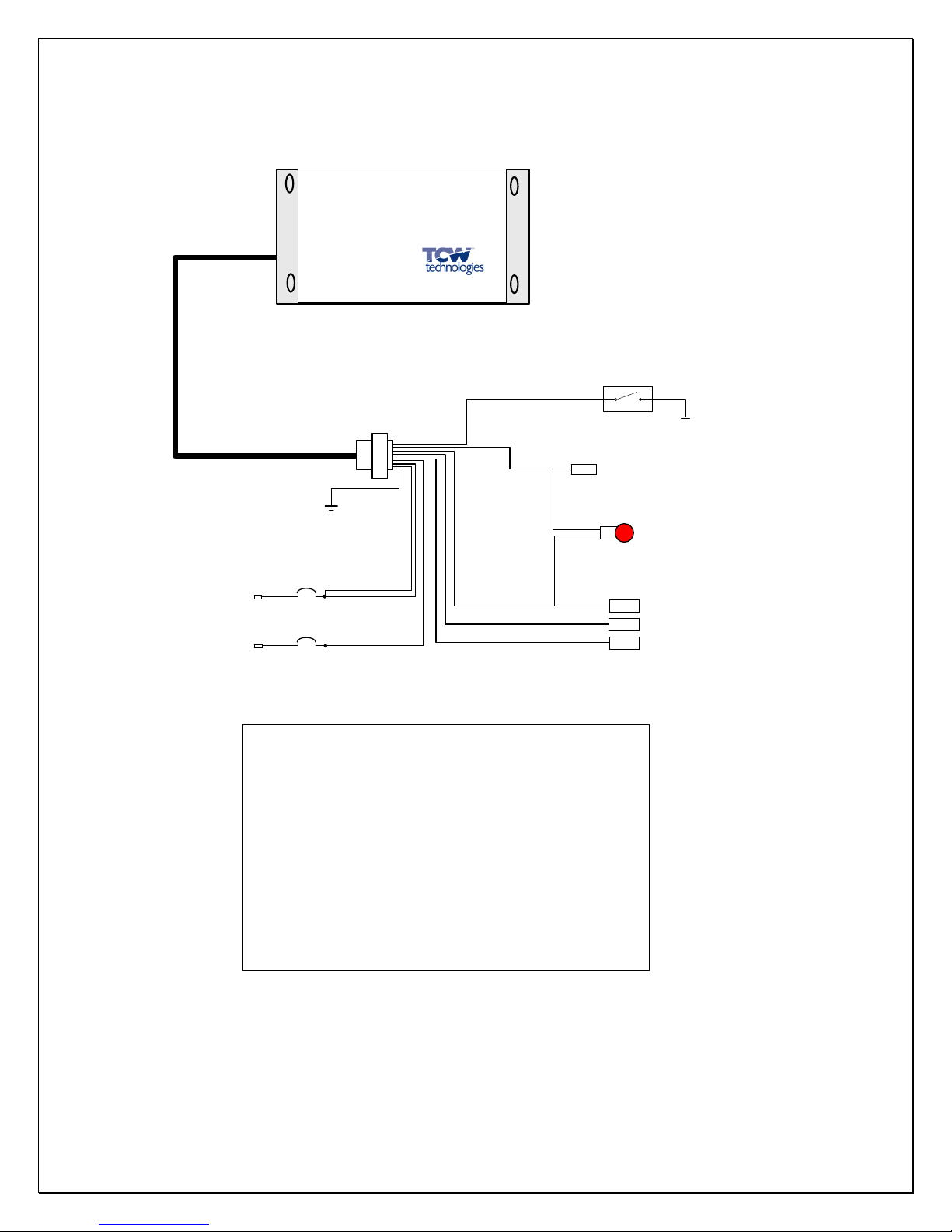
1) For Garmin 430/530, supply IBBS protected power only to gps/nav
power input, not com power input
Example wiring for systems ithout back up power inputs
quipment without Back-up Power Input
2 amps
10 amp
Main Aircraft Bus
Aux Battery
trickle charge
Back-up Power Master
cpc connector
INFO
Low = active signal
igh =battery voltage
Back-up power output
20 awg
22 awg
22 awg
20 awg
20 awg
22 awg
20 awg
www.tcwtech.com
mmaus, PA USA
MODEL: IBB-12V-2AH
Input: 10-15 volts DC
Output: 12 volts, 3 amps
Capacity: 2 amp-hours
INT GRAT D
Back-up Battery
SYST M
1
6
3
4
2
5
7
main power input
REV 2.3 © 2012 TCW Technologies, LLC.
14
Battery
Master Solenoid
Wiring Diagram IBBS-12v-2ah
Equipment being
powered via IBBS
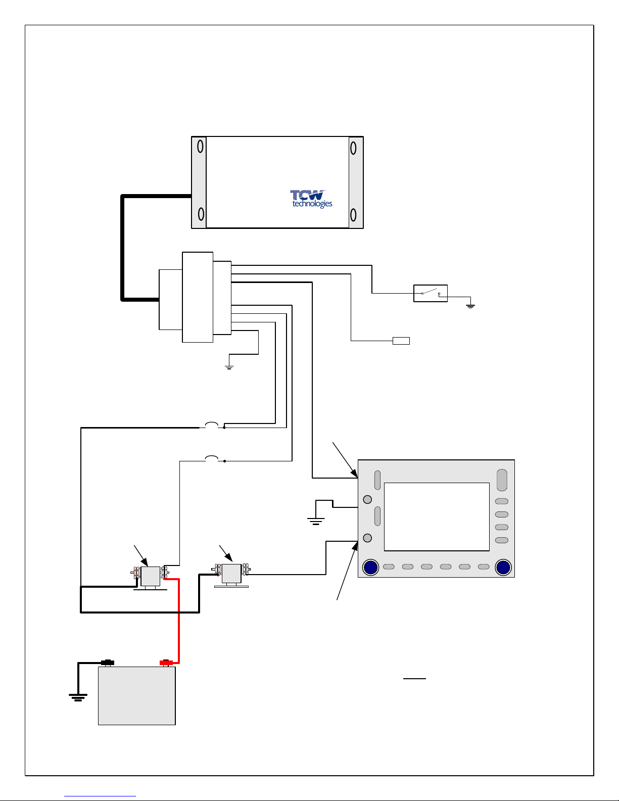
Example wiring for systems ith back up power inputs
quipment with Back-up Power Input
2 amps
10 amp
Main Aircraft Bus
Aux Battery
trickle charge
Back-up Power Master
cpc connector
INFO
Low = active signal
igh =battery voltage
Back-up power input
20 awg
22 awg
22 awg
20 awg
20 awg
22 awg
20 awg
www.tcwtech.com
mmaus, PA USA
MODEL: IBB-12V-2AH
Input: 10-15 volts DC
Output: 12 volts, 3 amps
Capacity: 2 amp-hours
INT GRAT D
Back-up Battery
SYST M
1
6
3
4
2
5
7
Avionics Bus Solenoid
main power input
Note: terminal 7, 8, 9 may be used for
back-up power outputs
Avionics Bus
REV 2.3 © 2012 TCW Technologies, LLC.
15
Main Aircraft Bus
20 awg Shielded
REV 2.3 © 2012 TCW Technologies, LLC.
16

REV 2.3 © 2012 TCW Technologies, LLC.
17
TCW Technologies, LLC.
During the first 12 months from the date of purchase and subject to the conditions hereinafter set forth, TCW
Technologies, LLC. (TCW) ill repair or replace to the original user or consumer any portion of your ne TCW product
hich proves defective due to defective materials or orkmanship of TCW. Contact TCW Technologies for arranty
service. TCW shall have and possess the sole right and option to determine hether to repair or replace defective
equipment, parts or components. Damage due to equipment, environment or conditions beyond the control of TCW
Technologies are NOT COVERED BY THIS WARRANTY.
LABOR, COSTS: TCW shall IN NO EVENT be responsible or liable for the cost of field labor or other charges incurred
by any customer in removing and/or reaffixing any TCW product, part or component thereof.
THIS WARRANTY WILL NOT APPLY: (a) to defects or malfunctions resulting from failure to properly install,
operate or maintain the unit in accordance ith printed instructions provided; (b) to failures resulting from abuse,
accident, or negligence; (c) to normal maintenance services and the parts used in connection ith such service; (d) to
units hich are not installed in accordance good trade practices; or (e) to unit used for purposes other than for hat it
as designed and manufactured.
RETURN OR REPLACED COMPONENTS: any item to be replaced under this Warranty must be returned to
TCW Technologies in Emmaus, PA, or such place as TCW may designate, freight prepaid.
PRODUCT IMPROVEMENTS: TCW reserves the right to change or improve its products or any portions
thereof without being obligated to provide such a change or improvement for units sold and /or shipped prior
to such change or improvement.
WARRANTY EXCLUSIONS: as to any specific TCW product, after the expiration of the time period of the
warranty applicable thereto as set forth above. THERE WILL BE NO WARRANTIES, INCLUDING ANY
IMPLIED WARRANTIES OR MERCHANTABILITY OR FITNESS FOR ANY PARTICULAR PURPOSE.
Some states do not allow limitations on how long an implied warranty lasts, so the above limitation may not
apply to you. No warranties or representations at any time made by any representative of TCW shall vary or
expand the provisions hereof.
LIABILITY LIMITATION: IN NO EVENT SHALL TCW OR ITS AFFILIATES BE LIABLE OR RESPONSIBLE
FOR CONSEQUENTIAL, INCIDENTAL OR SPECIAL DAMAGES RESULTING FROM OR RELATED IN ANY
MANNER TO ANY TCW PRODUCT OR PARTS THEREOF. THE SUITABILITY OF USE OF THE TCW
TECHNOLGIES, LLC. PRODUCT IS TO BE DETERMINED BY THE AIRCRAFT BUILDER.
Some states do not allow the exclusion or limitation of incidental or consequential damages, so the above
limitation or exclusion may not apply to you.
This Warranty gives you specific legal rights and you may also have other rights which vary from state to
state. In the absence of other suitable proof of this installation date, the effective date of this Warranty will be
based upon the date of manufacture plus one year. Direct All Notices To: Warranty and Product Service
Department, TCW Technologies, 2955 Main Road East, Emmaus, PA 18049
Table of contents


