te-lighting miniPAR TE-X18RGB User manual
TE-X18RGB miniPAR
Phonel : (1) 207-712-3004 http://www.te-lighting.com
USER MANUAL
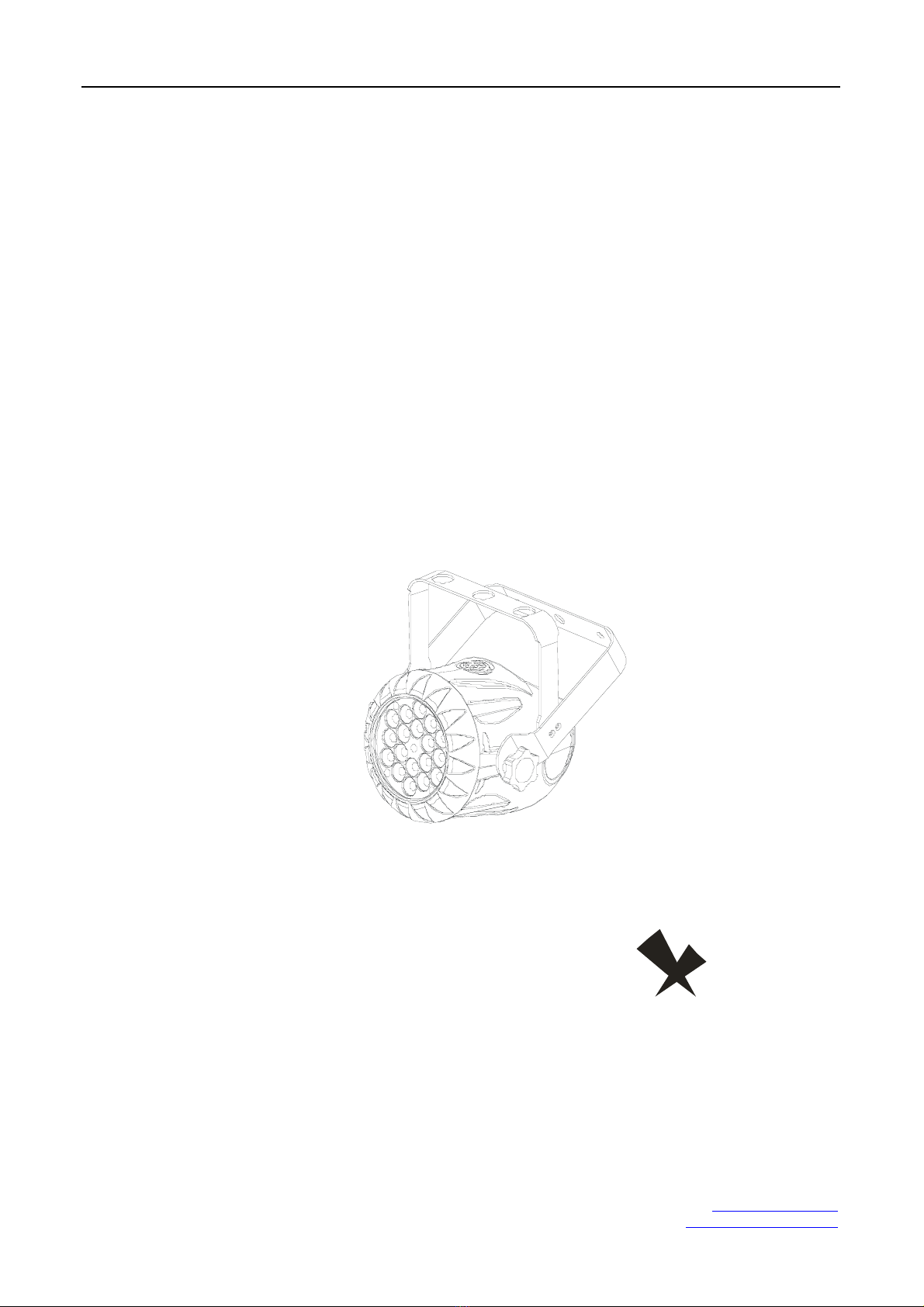
TE-X18RGB
miniPAR
YG-LED307
TE-LIGHTING

TE-X18RGB miniPAR
Phonel : (1) 207-712-3004 http://www.te-lighting.com
PART4 USINGADMX512 CONTROLLER....................................12.
4.1--BASICADDRESSING.................................................................12.
4.2--CHANNELASSIGNMENT............................................................12.
4.3--BASIC INSTRUCTIONSFOR DMX512OPERATION (STAGE 1).....15.
PART3 DISPLAYPANELOPERATION.........................................7.
3.1--BASIC..........................................................................................7.
3.2--MENU..........................................................................................6.
3.3--STATIC......................................................................................9.
3.4-- .........................................................................................9.AUTO
3.5--ADDRESS..................................................................................9.
3.6--RUN...........................................................................................10.
3.7-- ...................................................................................10.PERSON
3.8--ID..............................................................................................10.
3.9--EDIT ..........................................................................................10.
3.10--SETTINGS...............................................................................11.
3.11--PASSWORD .............................................................................11.
PART1 PRODUCT(GENERAL)....................................................1.
1.1--PRODUCTINTRODUCTION.........................................................1.
1.2 PRODUCT FEATURES-- .................................................................1.
1.3 TECHNICAL SPECIFICATIONS-- .....................................................2.
1.4 PHOTOMETRIC DATA-- ..................................................................3.
1.5 SAFETYWARNING-- ......................................................................4.
PART2 INSTALLATION...............................................................5.
2.1--MOUNTING...................................................................................5.
2.3--SETTING UPWITH ADMX512 CONTROLLER.................................6.
2.3-1--DMX512 A DDRESSING WITHOUTID ADDRES SING................. .....................6.
2.3-2--DMX512 ADDRESSING WITHI DADDRESS.......................................... ....... .6.
2.2--POWER CONNECTION..................................................................5.
3.12--SAVE.......................................................................................11.
PART5 APPENDIX..................................................................... 16.
5.1--TROUBLE SHOOTING...............................................................16.
5.2--MAINTENANCE........................................................................ 17
.
TABLEOF CONTENT
S

TE-X18RGB miniPAR
Phonel : (1) 207-712-3004 http://www.te-lighting.com
1.1 PRODUCT INTRODUCTION
This product is designed for indoor use. Suitable applications include wash or effect
lightingfor architectural, stage or nightclub applications. This product can also be installed
for use in signage and adver tising using the dynamic functions available with DMX512
control. Direct input of DMX512 signal allows the units to be controlled from anyDMX512
controller. This product can be operated as a single unit or in multiple units for large
applications.
The specially developed controller that allows the product to be controlled independent of
the DMX512 controllerenables the user to create and edit a w ide range of custom programs.
All programs can be touch-button displayed or scheduledto STARTand END at scheduled
times. When programs have been created or editedin the controller, it isalso possible to
triggertheseprogramsusingtheDMXINfunctionwhenconnected toa DMX512 controller.
1.2 PRODUCT FEATURES
LED FIXTURE
*RGBDimmer 0-100%
* Strobe
*Automatic programs
* LCD display
*Displaycontrol 'lock-out'
*DirectDMX512input
*IndependantID address
*Stand-alone/Slave
1
1PRODUCT (GENERAL)

TE-X18RGB miniPAR
Phonel : (1) 207-712-3004 http://www.te-lighting.com
1.3 TECHNICALSPECIFICATION
S
LED MODULE
Dimensions
LED MODULE:
Vo lt a g e
Rated Power
18pcs(6 x RED / 6x GR EEN/ 6 x BLUE )
Weig ht
LED/Un it
Output/LED
Co olin g
1W
Forced air convection
200 x 1 98 x148 mm
2.5Kg
100~240V...50/60Hz
30W
2
Environment Temperature -20 ~40℃℃
200mm
198mm
148mm
175mm
TE-X18RGB miniPAR
Phonel : (1) 207-712-3004 http://www.te-lighting.com
1.
4
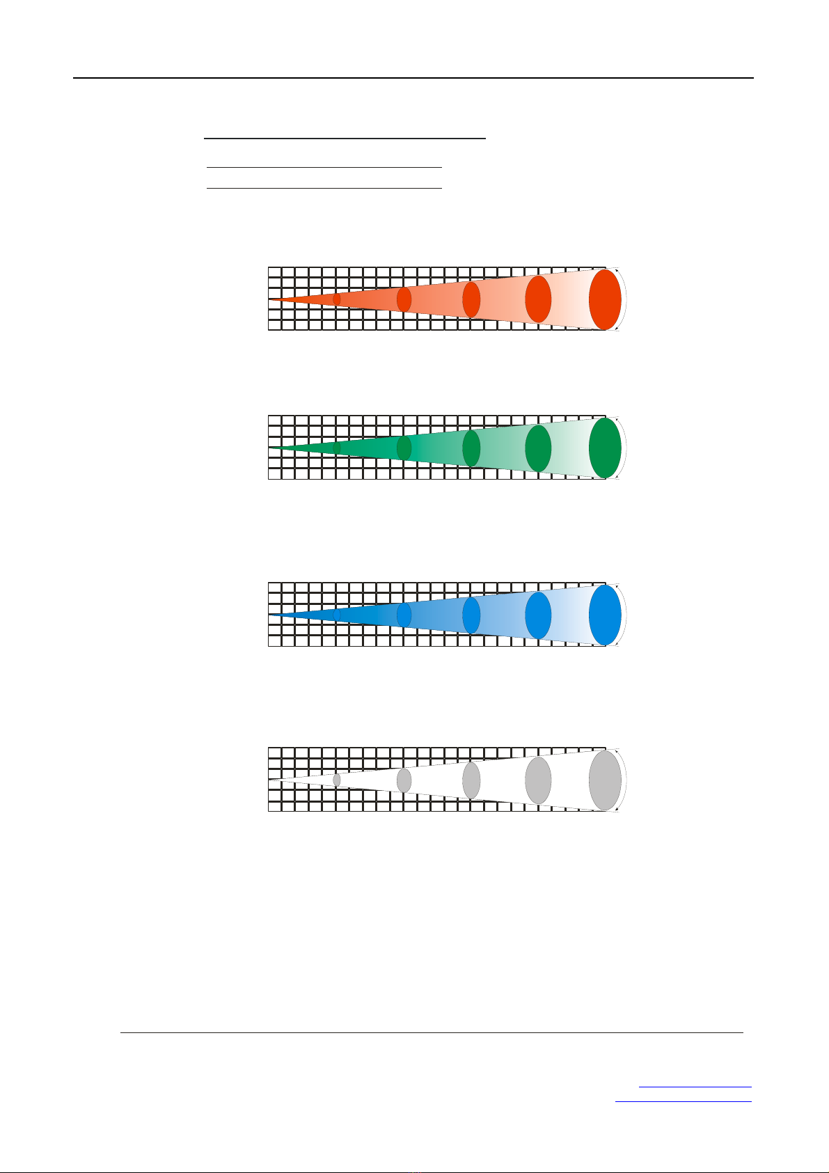
PHOTOMETRICDATA
PHOTOMETRIC DATA
3
RED
1
2
3
0
1
2
3
2(0.23) 4(0.43) 6(0.56) 8(0.93) 10Dist ance( m)
(1.12Diameter(m))
78 5 218 97 56 36 LU X
15°
GREEN
1
2
3
0
1
2
3
2(0.24) 4(0.41 ) 6(0.69) 8(1.02) 10Distance(m)
(1.02Diameter(m))
1136 320 161 86 58 LUX
15°
BLUE
1
2
3
0
1
2
3
2(0.23) 4(0.42 ) 6(0 .60) 8(0.88) 10Distance(m)
(1.12Diameter(m))
253 68 2 8 17.7 11 LUX
15°
RGB
1
2
3
0
1
2
3
2(0.23) 4(0.44) 6(0.68) 8(1.01) 10Distance(m)
(1.07 )Di am ete r( m)
2140 552 249 143 98 LU X
15°

TE-X18RGB miniPAR
Phonel : (1) 207-712-3004 http://www.te-lighting.com
1.5 SAFETYWARNING
IMPORTANT
【】
【
】
ALWAYSREADTHEUSERMANUALBEFOREOPERATION.
PLEASE CONFIRM THAT THE POWER SUPPLY STATED ON THE
PRODUCT ISTHESAMEASTHEMAINS POWER SUPPLYINYOUR
AREA.
●
●
●
●
●
●
●
●
●
●
T his product must be installed by a qualified professional.
Alwaysoperate theequipment as describedin theusermanual.
A minimum distance of 0.5m must be maintained between the equipment and
combustible surface.
T he product must alwaysbe placed in awell ventilatedarea.
Always make sure that the equipment isinstal led securely.
DO NOT stand close to the equipment and stare directly into the LED light
source.
Always disconnect the power supply before attempting and maintenance.
Always make sure that the supporting structure is solid and can support the
combined weight of theproducts.
T he earthwire must always be connected to the ground.
Do not touch the power cables if your hands are wet.
ATTENTION
●
●
●
●
●
●
●
●
T his product left the place of manufacture in perfect condition. In order to
maintainthis condition and for safe operation, the user must always follow the
instructions and safety warnings described in this user manual.
Avoid shaking or strong impacts to any part of the equipment.
Make surethat all parts of the equipment are kept cleanand free of dust.
Always make sure that the power connections are connected correct and
secure.
If there isany malfunction of the equipment, contact your distributor
immediately.
Whentransferringtheproduct, itis advisabletousetheoriginalpackaging in
which theproduct left thefactory.
Shields,lenses or ultravioletscreens shall be changedifthey havebecome
damagedtosuchanextentthattheireffectiveness isimpaired.
The lamp(LED) shall bechanged ifithas becomedamagedor thermally
deformed.
4

TE-X18RGB miniPAR
Phonel : (1) 207-712-3004 http://www.te-lighting.com
2.1 MOUNTING
HANGING
UPRIGHT
The LED PAR can be mounted in an upright or
sitting position using the supporting brackets.
The LED PAR can be mounted in a hanging position using thesupporting bracket.
The bracket should be secured to the mounting truss or structure usin g a
standard mountingclamp. Please note that when hanging the unit a safety cable
should also be used.
@ 220V: 40 units may be connected in series
@120V: 20 units may be connected in series
The LED MODULEcan be mountedat any angleand in any
position. It is possible to further adjust th e angle of the LED
MODULE using the tw o adjustment knobs located on the side of
the fixture.
2.2 POWER CONNECTIONS
5
Note: Asthis fixture'sDMXsignal cableconnectionhadbeen changed toParallelconnection,
so if over 30 unitstobe connected, thena DMXsignal amplifier is needed.
2INSTALLATION

TE-X18RGB miniPAR
Phonel : (1) 207-712-3004 http://www.te-lighting.com
2.3
SETTING UP WITHADMX512
CONTROLLER
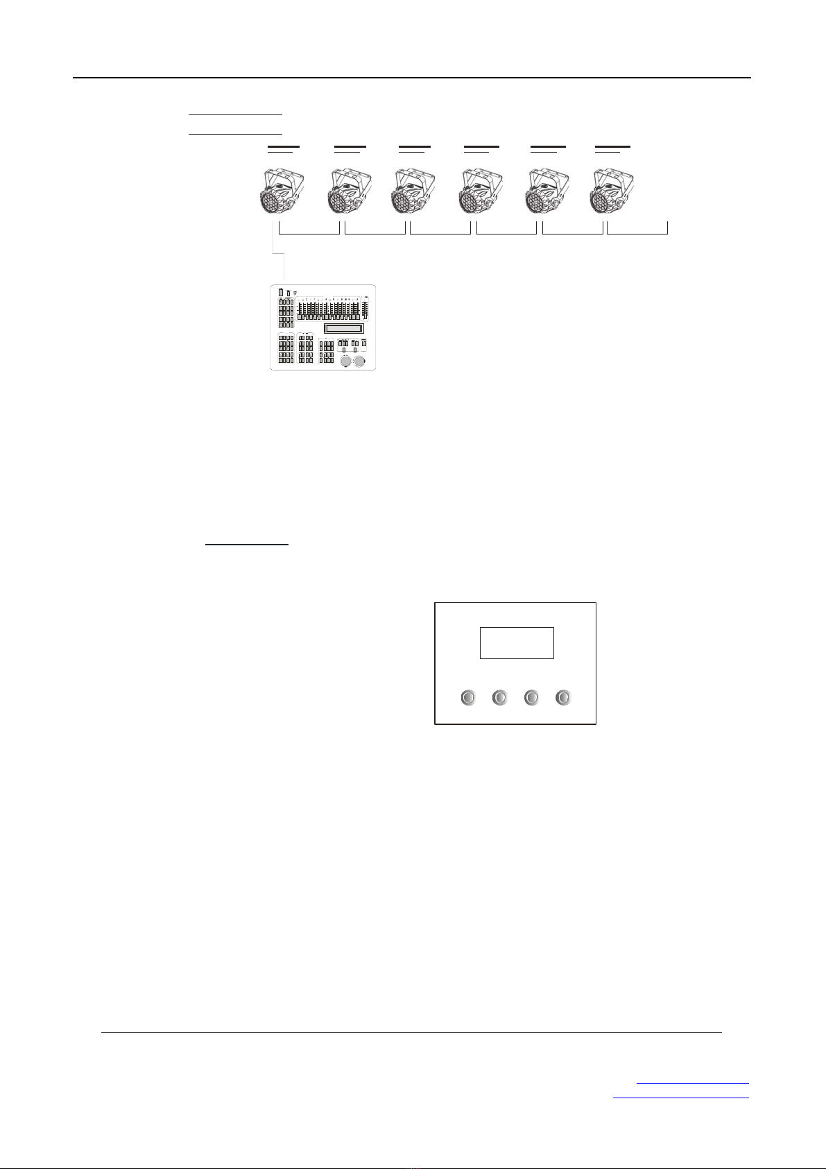
2.3-1 DMX512ADDRESSING WITHOUT IDADDRESSING
STAGE 1 MODE)(
The figureaboveshows asimpleDMX512
layoutwiththestartingaddress of thefirst
unit set at1, with the second set at 10 and
so on... (Note that when used in this way,
the CH9 ID function mustbe inactive (CH9=0))
DMX512
CONTROLLER
●
●
●
●
●
Connect the DMX512 controller to the units in series.
Eachunit has 9 DMX channelsso the DMXAddressesshould increase by incrementsof
9(e.g. 1,10,19,28...)
The ID address has not been set so therefore whenusing the controller Ch9 must
be inactive ( CH9=0 ).
EachDMXAddress may beusedasmanytimesasrequired.
AnyDMXaddressintherange from001to512 may be used.
2.3-2 DMX512ADDRESSING WITH IDADDRESS STAGE 1 MODE)(
Connect the DMX512 controller to the units in series
Eachunit has 9DMXchannels so the DMXAddresses should increase byincrements of
9(e.g. 1,10,19,28...)
EachDMXAddress may beusedasmanytimesasrequired.
AnyDMXaddressintherange from001to512 may be used.
EachDMX address may carry up to 66 separate IDaddresses.
should be set in the menu on each unit in ascending values
(i.e. 1,2,3...)
ID addresses are accessible from Ch9 on the DMX512 controller.
●
●
●
●
●
●
●
【】ID
Example:
............
6
TE-X18RGB miniPAR
Phonel : (1) 207-712-3004 http://www.te-lighting.com
DM X512
CONTROLLER
Example:
Thefigureaboveshows asimpleDMX layout
which has used three units at each DMX address.
Thethree units havedifferentIDaddresseswhich
allows theuser tocollectivelycontrolthewhole
group of unitsatthatDMXaddress bysetting
CH9 to 0, or to control each unit independently by
first selecting the DMX address and then by using
Ch9 to locate the target IDaddress.
............
7
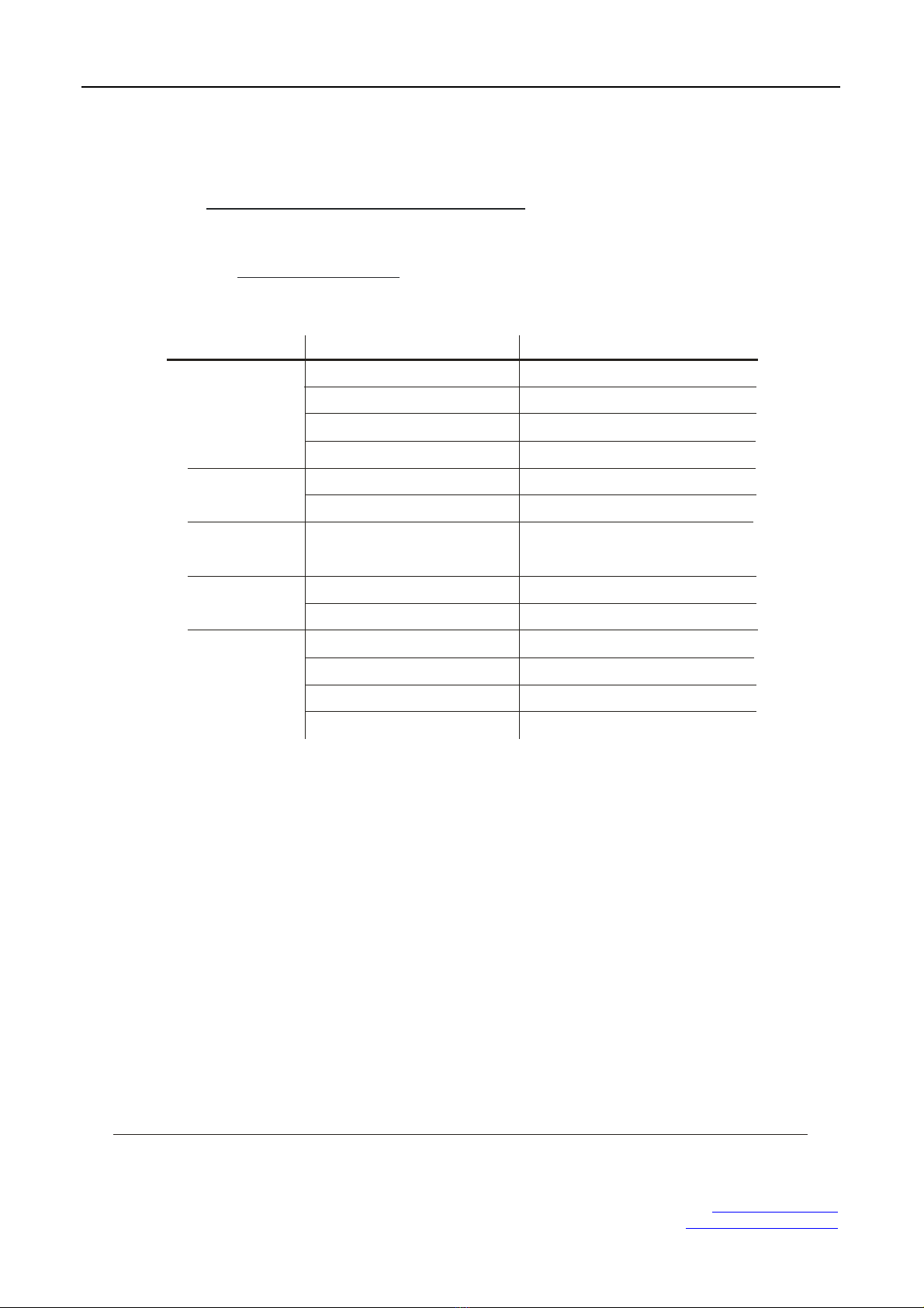
3.1 BASIC
DOWN
ENTER UPMENU
【】
【】
【】
【】
MENU
ENTER
scroll through the main menu or exit fromthecurrentmenuor function
Enter thecurrently selected menu or confirm the current function value
UP
DO WN
scroll 'UP' through themenu list or increase the value of thecurrentfunction
scroll 'DOWN' through the menu list ordecrease the valueofthecurrent function
3DISPLAY PANEL OPERATION

TE-X18RGB miniPAR
Phonel : (1) 207-712-3004 http://www.te-lighting.com
3.2 MENU
STATIC
AUTO
ADDRESS
RUN
PASS WORD
PERSON
ID
EDIT
SETTINGS
GREN 000~255【】
BLUE 000~255【】
STRB 000~020【】
RED 000~255【】
AUTO 1
【】001~512
SLAVE
【】ON/OFF
STAGE1
DMX
ARC1
ARC1+D
AUTO 2
AUTO 3
AUTO 4
AUTO 5
AUTO 6
AUTO 7
AUTO 8
AUTO 9
AUTO 10
custom 1
custom 2
custom 3
custom 4
custom 5
custom 6
custom 7
custom 8
custom 9
custom 10
【】001~066
custom1
ID
ON/OFF【】
Reset to
Factory?
Upload
costom?
custom2
custom3
custom4
custom5
custom6
custom7
custom8
custom9
custom10
scene 01
scene 02
scene 03
scene 04
scene 05
scene 06
scene 30
GREN 000~255【】
BLUE 000~255【】
STRB 000~020【】
TIME 000~255【】
FADE 000~255【】
RED 000~255【】
MENU
8

TE-X18RGB miniPAR
Phonel : (1) 207-712-3004 http://www.te-lighting.com
3.3 STATIC
3.4 AUTO
【】
● 【 】【 】【 】【 】
STATIC
RED GREN BLUE STRB
Select / / / to setthe value
【】
●【】 【】
●【】【】
●【】【 】
AUTO
AUTO ENTER
AUTO 1 AUTO 10
Custom 1 Custom 10
Select the target program and pres s
Programs to are fully pre-programmed and will not be
altered
Programs to are fullypre-programmedandcan be
edited
9
STATIC GREN 000~255【】
BLUE 000~255【】
STRB 000~020【】
RED 000~255【】
MENU
AUTO AUTO 1
AUTO 2
AUTO 3
AUTO 4
AUTO 5
AUTO 6
AUTO 7
AUTO 8
AUTO 9
AUTO 10
custom 1
custom 2
custom 3
custom 4
custom 5
custom 6
custom 7
custom 8
custom 9
custom 10
MENU
3.5 ADDRESS
【】
●【 】 【 】
ADDRESS
ADDRE SS 001~512
Enter andset the DMX address
ADDRESS 【】001~512
MENU

TE-X18RGB miniPAR
Phonel : (1) 207-712-3004 http://www.te-lighting.com
10
3.
6
RUN
【】
●【】 【 】【】
RUN
RUN SL AVE DMX
Enter to choose or working mode
RUN SLAVE
DMX
MENU
3.7 PERSON
PERSON STAGE1
ARC1
ARC1+D
MENU
【】
●【 】 【 】【】【 】
PERSON
PERSON STAGE1 ARC1 ARC1+D
Enter andselect / / DMXmode
3.8 ID
ID 【】001~066
MENU
ID
【】
【】 【 】
●001~06 6
Enter andsettheID address
ID
3.9 EDIT
【】
【】 【 】【 】
EDIT
EDIT custom1 custom10
●
●
●
Enter to edit the custom programs to
Each program has 30 steps to edit
Each step allows a creation of a scene using RED,GREEN,BLUE,STRUBE,TIME,
FADE
EDIT custom1
custom2
custom3
custom4
custom5
custom6
custom7
custom8
custom9
custom10
scene 01
scene 02
scene 03
scene 04
scene 05
scene 06
scene 30
GREN 000~255【】
BLUE 000~255【】
STRB 000~020【】
TIME 000~255【】
FADE 000~255【】
Red 000~255【】
MENU

TE-X18RGB miniPAR
Phonel : (1) 207-712-3004 http://www.te-lighting.com
11
3.10 SETTING
S
SETTINGS ID
ON/OFF【】
Reset to
Factory?
Upload
custom?
MENU
ID
【】
【】【 】
【】
【】
【】
●
●
●
ResettoFactory?
Upload custom?
Up load custom?
Choose / toopenor close ID
This function will reset all setting to theoriginal factorysetting
ON OFF
Select to uploadthe customprograms fromthecurrent
MASTER unit to the SLAVE units
3.11 PASSWORD
3.12 SAVE
●
●
Only themainmenuandtheAuto-programs submenucanbe protected
Repowerthe unit, it willback to the mainmenu
【】
PASSWORD
●
●
ChoosingON, the operation board will be underpassword protection after 30s
without operation
ChoosingOFF, you will be able to operate at anytime freely
PASS WORD 【】ON/OFF
MENU

TE-X18RGB miniPAR
Phonel : (1) 207-712-3004 http://www.te-lighting.com
4.1 BASICADDRESSING
●
●
●
Connect all of the units in series usingstandard DMX512 signal cableor the IP65 ratedcable
provided.
Set the DMX512 address in the menu.
Itis possibletohavethe same DMXaddress orindependent addresses for eachfixture.
【】DMX
4.2 CHANNELASSIGNMENT
12
●
Note: This product have three DMX512channel configuration: , and【】【】
【】 STAGE 1 ARC 1
ARC1+D
1
2
0 255
3
4
0 255
0 255
0 255
5
0 10
11 35
36 60
61 85
86 110
111 135
136 160
161 185
186 210
211 215
216 220
221 225
226 230
231 235
236 240
241 245
246 250
251 255
RED 100%/ GREEN UP / BLUE0%
RED DOWN / GREEN 100% / BLUE 0%
RED 0% / GREEN 100%/ BLUE UP
RED 0% / GREEN DOWN / BLUE 100%
RED UP /GREEN 0% /BLUE 100%
RED 100%/ GREEN 0% / BLUE DOWN
RED 100%/ GREEN UP / BLUEUP
RED DOWN / GREEN DOWN /BLUE 100%
WHITE 1:3200K
WHITE 2:3400K
WHITE 3:4200K
WHITE 4:4900K
WHITE 5:5600K
WHITE 6:5900K
WHITE 7:6500K
WHITE 8:7200K
WHITE 9:8500K
MAR CO
No function
Ch2 will control the TIMEifCh7 choose custom01-10
DIMMER
Ch3 willcontrolthe FADE if Ch7choose CUSTOM01-10
STAGE 1
BLUE
CHANNEL FUNCTIONVALUE
GREEN
RED
6
0 10
11 255 Strobespeed
STROBE
No function
4USINGADMX512 CONTROLLER

TE-X18RGB miniPAR
Phonel : (1) 207-712-3004 http://www.te-lighting.com
0 20
21 30
31 40
41 50
51 60
61 70
71 80
81 90
91 100
101 110
AUTO 1
AUTO 2
AUTO 3
AUTO 4
AUTO 5
AUTO 6
AUTO 7
AUTO 8
AUTO 9
111 120 AUTO 10
AUTO
No function
7
CUSTOM 2
CUSTOM 3
CUSTOM 4
CUSTOM 5
CUSTOM 6
CUSTOM 7
CUSTOM 8
CUSTOM 9
CUSTOM 10
121 130
131 140
141 150
151 160
161 170
171 180
181 190
191 200
201 210
0 255
CUSTOM 1
8
211 220
221 255
When usingCH7,AUTO01-AUTO9,thisfunction activated
No function
AUTO SPEED ADJUSTMENT
CHANNEL FUNCTIONVALUE
13
IDADDRESS
ID1~ID66
ID1
ID2
ID3
ID4
ID5
ID6
ID7
ID8
ID9
ID10
ID11
ID12
ID13
ID14
ID15
0 9
10 19
20 29
30 39
40 49
50 59
60 69
70 79
80 89
90 99
100 109
110 119
120 129
130 139
140 149
150 159
9
ID16
ID17
ID18
ID19
160 169
170 179
180 189
190 199

TE-X18RGB miniPAR
Phonel : (1) 207-712-3004 http://www.te-lighting.com
9
ID21
ID22
210
211
CHANNEL FUNCTIONVALUE
14
ID20
200 209
ID64
ID65
ID66
253
254
255
ARC 1
BLUE
1
2
0 255
CHANNEL FUNCTIONVALUE
3
0 255
0 255
GREEN
RED
ARC 1+D
BLUE
1
2
0 255
CHANNEL FUNCTIONVALUE
3
4
0 255
0 255
0 255
GREEN
RED
MASTER DIMMER

TE-X18RGB miniPAR
Phonel : (1) 207-712-3004 http://www.te-lighting.com
4.3
BASIC INSTRUCTIONS FORDMX512
OPERATION (STAGE 1)
MASTER DIMMER
RED,GREEN& BLUECOLOR SELECTION
COLOR MACROS
STROBE
IDADDRESS SELECTION
AUTO
●
●
●
●
●
●
●
●
●
●
●
●
●
●
CH1 controls the intensityof the currently projected color
When the slider is at the highest position (255) the intensity of the output is the maximum
CH2, CH3 & CH4 control the intensity ratio of each of theRED, GREEN& BLUE LEDs.
When the slider is at the highest position (255) the intensity of the coloris the maximum.
CH2, CH3 & CH4 can be combined together to create over 16 million colors.
CH5 selects therequiredCOLOR MACRO
CH5 has priority over CH2, CH3 , CH4 and CH6
CH1 isused to control theintensityof theCOLOR MACRO
CH 6 controls the strobe of C H1 to Ch5
CH9 is used to select thetarget ID address .
Each independent DMX address may have upto 66 independent ID addresses.
An ID address of 0 will activate allID address locations.
CH7 selects thepresetAUTO programsAT.01-AT10or the customAUTO programs PR.C1-
PR.10
When activating the custom AUTO programs PR.C1 to PR.10 then it is possible to control the
Step time and fade time using Ch2 and Ch3 respectively.
15
TE-X18RGB miniPAR
Phonel : (1) 207-712-3004 http://www.te-lighting.com
No display
1 Power connection error)
2)Power switch damaged
3)Disp lay boar d damaged
1 Check allpowerconnections)
2) Re place po wer switch
3) Re place display board
LED MODULE on,
but no control
from display 2 Disp lay boar d damag ed) 2 Replace displayboard)
LEDsof thesame
colorarenotlit LEDPCB damaged
Check andReplacePCB board
SITUATION CAUSE ACTION
LEDmodule on,
LEDsof all colors
arenotlit
1)MAINPCB damaged 1) Replace main PCB b oard
Displaynormal,
butnoresponse
toDMX512
controller
1 Signalconnectionerror)
2DMXAddresserror)
1 Check andreplace signal cable)
2 Checkand reset DMX address)
3 Master & slavemode error)
4 ID error)
3 Check andreset the working mode)
4 Check and rese t ID address)
5.1 TROUBLE SHOOTING
1 Keyboarddamaged) 1 Replace keyboard)
2 LED PCBdamaged) 2 Replace PCBboard)
LED MODULE
16
4)Fusedamaged 4)Replacethe Fuse
5
APPENDIX
TE-X18RGB miniPAR
Phonel : (1) 207-712-3004 http://www.te-lighting.com
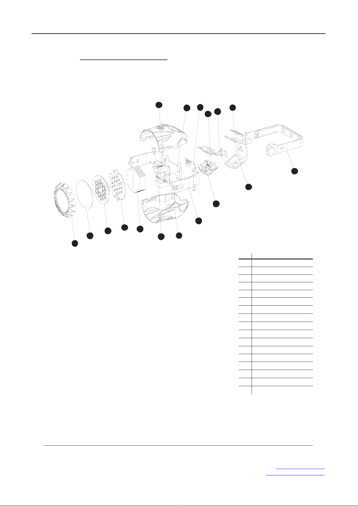
5.2 MAINTENANCE
1
2345
67
8
9
10
11
12
13
14
15
16
17
17
No
ITEM
1
2
3
4
5
6
7
8
9
10
11
12
13
14
15
16
17 Switch
Pla stic cover
dustproofglass
Lenswheel
Le d board
Co oling
Fa ns
Pla stic side cover
Sid e board
DM X board
Po wer boa rd
Fusesocket
Ma in board
Dri ver board
LCD plastic cover
Displaysupport
Ho lder
TE-X18RGB miniPAR
Phonel : (1) 207-712-3004 http://www.te-lighting.com
Table of contents


