LED High In ensi y Warning Ligh
Par 0-441-05
SAFETY WARNING
1. Proper installation of this product requires the installer to have a good understanding of automotive electronics, sys-
tems and procedures.
2. If mounting this product requires drilling holes, the installer UST be sure that no vehicle components or other vital
parts could be damaged by the drilling process. Check both sides of the mounting surface before drilling begins. Also
de-burr the holes and remove any metal shards or remnants.
3. Do not install this product or route any wires in the deployment area of your air bag. Equipment mounted or located
in the air bag deployment area will damage or reduce the effectiveness of the air bag, or become a projectile that could
cause serious personal injury or death. Refer to your vehicle owner’s manual for the air bag deployment area. The User/
Installer assumes full responsibility to determine proper mounting location, based on providing ultimate safety to all
passengers inside the vehicle.
4. Do not attempt to activate or control this device in a hazardous driving situation.
5. This product contains either strobe light(s), halogen light(s), high-intensity LEDs or a combination of these lights. Do
not stare directly into these lights. omentary blindness and/or eye damage could result.
6. Use only soap and water to clean the outer lens. Use of other chemicals could result in premature lens cracking (craz-
ing) and discoloration. Lenses in this condition have significantly reduced effectiveness. Inspect and operate this product
regularly to confirm its proper operation and mounting condition. Do not use a pressure washer to clean this product.
7. It is recommended that these instructions be stored in a safe place and referred to when performing maintenance and/
or reinstallation of this product.
8. For this product to operate at optimum efficiency, a good electrical connection to chassis ground must be made. The
recommended procedure requires the product ground wire to be connected directly to the NEGATIVE (-) battery post.
9. All connections must use waterproof connectors and any unconnected wires must be sealed to prevent water ingress
via the wire core, failure to do this may result in premature failure and invalidate the warranty.
MOUNTING
1. Place the unit against the mounting surface.
2. ark the areas where the mounting holes are to be drilled. Confirm that no vehicle parts could be damaged by the
drilling process.
3. Using a bit size for a no. 304 metal screw, drill two mounting holes, a 0.5” diameter. Wire passage hole(s) must also
be drilled. Thouroughly de-burr all hole(s).
4. Pass the wires through the hole(s) in the gasket and through the wire passage hole(s) in the mounting surface. Fix the
light head to the mounting surface.
WWW.DURITE.CO.UK 0-441-05-LEAFL
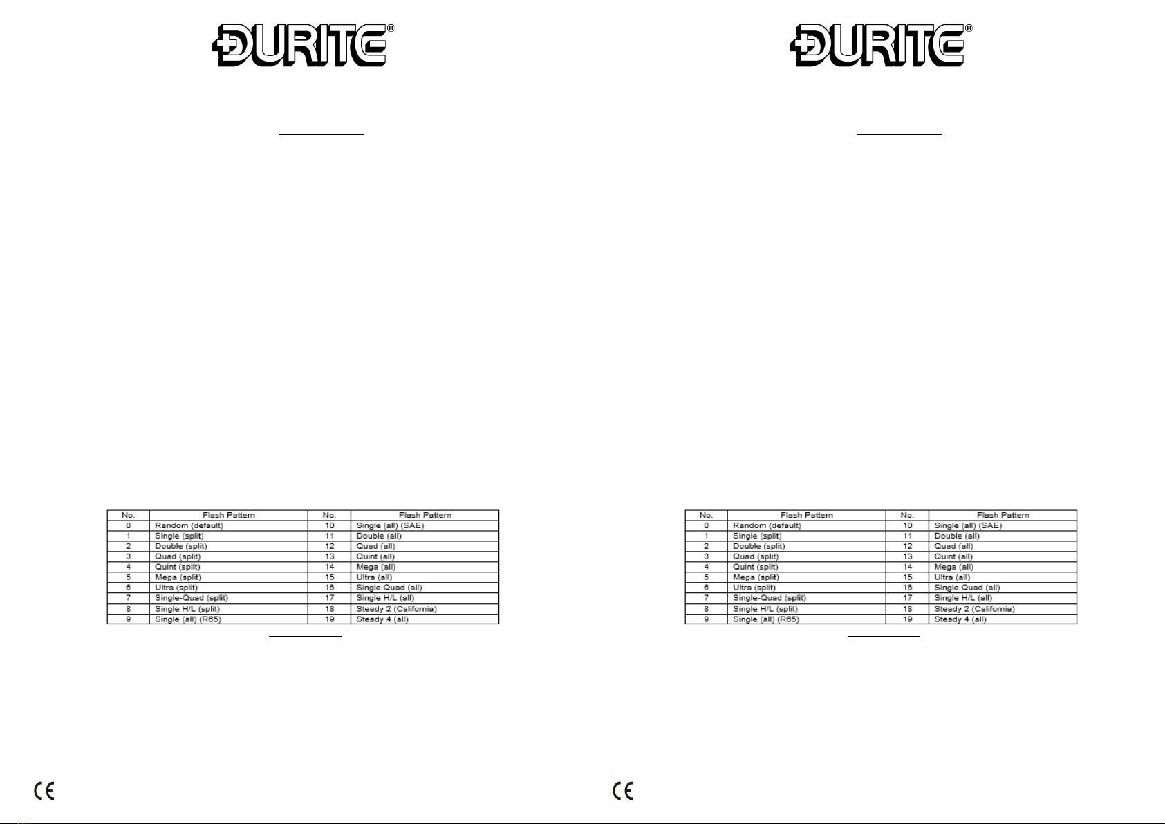
WIRING DIAGRAM
LED High In ensi y Warning Ligh
Par 0-441-05
WARNINGS
Before using this unit please read these instructions carefully. Take special care to follow the warnings and
safety suggestions listed below. Keep these instructions for future reference.
SAFETY WARNING
1. Proper installation of this product requires the installer to have a good understanding of automotive electronics, sys-
tems and procedures.
2. If mounting this product requires drilling holes, the installer UST be sure that no vehicle components or other vital
parts could be damaged by the drilling process. Check both sides of the mounting surface before drilling begins. Also
de-burr the holes and remove any metal shards or remnants.
3. Do not install this product or route any wires in the deployment area of your air bag. Equipment mounted or located
in the air bag deployment area will damage or reduce the effectiveness of the air bag, or become a projectile that could
cause serious personal injury or death. Refer to your vehicle owner’s manual for the air bag deployment area. The User/
Installer assumes full responsibility to determine proper mounting location, based on providing ultimate safety to all
passengers inside the vehicle.
4. Do not attempt to activate or control this device in a hazardous driving situation.
5. This product contains either strobe light(s), halogen light(s), high-intensity LEDs or a combination of these lights. Do
not stare directly into these lights. omentary blindness and/or eye damage could result.
6. Use only soap and water to clean the outer lens. Use of other chemicals could result in premature lens cracking (craz-
ing) and discoloration. Lenses in this condition have significantly reduced effectiveness. Inspect and operate this product
regularly to confirm its proper operation and mounting condition. Do not use a pressure washer to clean this product.
7. It is recommended that these instructions be stored in a safe place and referred to when performing maintenance and/
or reinstallation of this product.
8. For this product to operate at optimum efficiency, a good electrical connection to chassis ground must be made. The
recommended procedure requires the product ground wire to be connected directly to the NEGATIVE (-) battery post.
9. All connections must use waterproof connectors and any unconnected wires must be sealed to prevent water ingress
via the wire core, failure to do this may result in premature failure and invalidate the warranty.
MOUNTING
1. Place the unit against the mounting surface.
2. ark the areas where the mounting holes are to be drilled. Confirm that no vehicle parts could be damaged by the
drilling process.
3. Using a bit size for a no. 304 metal screw, drill two mounting holes, a 0.5” diameter. Wire passage hole(s) must also
be drilled. Thouroughly de-burr all hole(s).
4. Pass the wires through the hole(s) in the gasket and through the wire passage hole(s) in the mounting surface. Fix the
light head to the mounting surface.
WWW.DURITE.CO.UK 0-441-05-LEAFL
WIRING DIAGRAM
WARNINGS
Before using this unit please read these instructions carefully. Take special care to follow the warnings and safety
suggestions listed below. Keep these instructions for future reference.