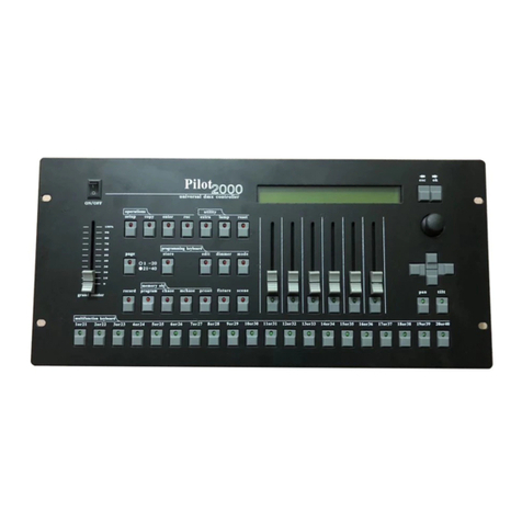
Teatronics Lighting Controls 224 User manual

PRODUCER 3
06/18/97
Lighting Control Console page
TEATRONICS LIGHTING CONTROLS,TEATRONICS LIGHTING CONTROLS, INC.INC.
TEATRONICS LIGHTING CONTROLS, INC.
1236 Los Osos Valley Road Suite G1236 Los Osos Valley Road Suite G
Los Osos , California 93402Los Osos , California 93402
Phone: (805)528-6900Phone: (805)528-6900
FAX: (805)528-9345FAX: (805)528-9345
06/17/97
Owner's Manual
PRODUCER 3
Model 224, 236, 248
Lighting Control Console

PRODUCER 3
06/18/97
Lighting Control Console page
TEATRONICS LIGHTING CONTROLS,TEATRONICS LIGHTING CONTROLS, INC.INC.
i
RECEIVING YOUR EQUIPMENT
As soon as you have received your equipment, open the boxes and examine the equipment inside. If any
damage is noted, contact the carrier immediately to file a claim for damages. When the equipment left
the factory it was in good condition and properly packed.
If you find the equipment to be in accordance with your order and the packing list, and also in good
condition, you may read on to the section covering SETUP and CONNECTION. If for some reason the
equipment in the carton does not agree with your order or the packing list, contact the factory immediately
and we will help solve the mystery.

PRODUCER 3
06/18/97
Lighting Control Console page
TEATRONICS LIGHTING CONTROLS,TEATRONICS LIGHTING CONTROLS, INC.INC.
ii
PREFACE
Unauthorized repair on our products shall void the warranty, and the buyer may be charged for
subsequent factory repair, even though the product is defective. All repairs should be done at
authorized service stations by factory trained technicians. In situations where this is not feasible,
this service manual is intended as a guide for emergency field repairs, including replacement of
triacs, circuit boards, and some mechanical assemblies.
Replacement parts should be ordered from the factory and will be shipped by United Parcel
Service. Tested replacement circuit boards carry a 90 day warranty. Defective circuit boards
may be returned to the factory for repair. All replacement parts and circuit boards must be paid
for. Reimbursements shall not be made in return for defective parts.
Call the factory service department for any information about our service policy or for help in
repairing a unit. Differences may exist between this manual and units in the field. Up-to-date
information is available free of charge from the Teatronics Lighting controls, Inc., Service
Department at (805) 528-6900 from 8:00 am to 5:00 pm Pacific Standard Time.

PRODUCER 3
06/18/97
Lighting Control Console page
TEATRONICS LIGHTING CONTROLS,TEATRONICS LIGHTING CONTROLS, INC.INC.
iii
INTRODUCTION
Thank you for buying an Teatronics Lighting controls, Inc. PRODUCER 3 control console.
Please read this manual thoroughly to understand your unit and to insure that you get the most
out of it.
The purpose of the owner's manual is to assist you in becoming familiar with your Producer 3:
its installation, operation, troubleshooting, and maintenance. Ownership of a sophisticated
piece of electronic equipment involves more than just "buy it and use it". The Producer was
designed in response to users' requests for many features they felt were important. These features
lie beneath the simplicity of appearance. To fully appreciate them and what they can do for
you, read on.
Take the time and care to follow these instructions and your Producer 3 console should provide
you with long-lasting quality lighting control.

PRODUCER 3
06/18/97
Lighting Control Console page
TEATRONICS LIGHTING CONTROLS,TEATRONICS LIGHTING CONTROLS, INC.INC.
iv
TABLE OF CONTENTS
RECEIVING YOUR EQUIPMENT ...................................................................................... i
PREFACE .................................................................................................................... ii
INTRODUCTION .............................................................................................................. iii
TABLE OF CONTENTS ..................................................................................................iv-v
TABLE OF EXAMPLES .....................................................................................................vi
SETUP AND CONNECTION ..............................................................................................1
Mechanical Installation.............................................................................................1
Electrical Installation ................................................................................................1
Interface to Dimmers ................................................................................................2
Grounding ................................................................................................................3
OPERATION .....................................................................................................................4
Getting Up and Running ...........................................................................................4
Understanding the Patch ...........................................................................................6
Record Mode............................................................................................................8
Recording Dimmer Assignments ...................................................................8
Recording Submaster Assignments..............................................................12
Altering Submaster Assignments.................................................................15
Programming Chase Sequences...................................................................17
Copying Shows ...........................................................................................22
Play Mode ..............................................................................................................22
Reviewing Dimmer Assignments ................................................................22
Reviewing Channel Assignments ................................................................24
Reviewing Submaster Assignments .............................................................25
Reviewing Chase Sequences .......................................................................26
Selecting Chase Sequences..........................................................................27
Play Mode Chase Modifiers ........................................................................28
Changing Shows .........................................................................................29

PRODUCER 3
06/18/97
Lighting Control Console page
TEATRONICS LIGHTING CONTROLS,TEATRONICS LIGHTING CONTROLS, INC.INC.
v
TABLE OF CONTENTS (continued)
KEY FUNCTIONS.............................................................................................................30
Sequencer................................................................................................................33
SPECIAL FEATURES........................................................................................................34
Viewing the version of software ..............................................................................34
Initializing the Patch................................................................................................34
Initializing the Submasters ......................................................................................34
Clearing a Single Submaster....................................................................................35
Initializing the Chase...............................................................................................35
One Scene 48 Channel Operation ............................................................................35
One Scene 96 Channel Operation ............................................................................35
IN CASE OF TROUBLE....................................................................................................36
Trouble Shooting.....................................................................................................36
Self Diagnostic Techniques......................................................................................39
Sorting out the AMX Signals...................................................................................40
PERIFERALS.....................................................................................................................42
Disk Drive...............................................................................................................42
CRT Display............................................................................................................43
REFERENCE TABLES ......................................................................................................44
Appendix I - Default Patch Table.............................................................................45
Appendix II - Softpatch Cross Reference Table .......................................................46
Appendix III - Recorded Submasters Reference Table .............................................47
Appendix IV - Producer 3 Quick Reference Sheet ...................................................48
WARRANTY .....................................................................................................................49

PRODUCER 3
06/18/97
Lighting Control Console page
TEATRONICS LIGHTING CONTROLS,TEATRONICS LIGHTING CONTROLS, INC.INC.
vi
TABLE OF EXAMPLES
RECORD MODE
Patch Assignments:
1 Assigning a single dimmer to a channel at full .....................................................8
2 Assigning a series of dimmers to a channel at full ................................................9
3 Assigning a series of dimmers to a channel at various levels ..............................10
4 Using the clear key to correct mistakes ..............................................................11
5 Removing a dimmer from a channel ..................................................................11
Submaster Assignments:
6 Assigning channels to a submaster.....................................................................12
7 Using one submaster to build another submaster................................................13
8 Adding channels to a previously recorded submaster .........................................14
9 Increasing the level of a channel in a submaster.................................................16
10 Decreasing the level of a channel in a submaster...............................................16
Programming Chases:
11 Recording a simple four channel chase .............................................................18
12 Recording a complex chase sequence................................................................19
13 Recording a blackout step in a chase.................................................................20
14 Error display when programming too long a chase............................................21
PLAY MODE
Patch Review:
15 Reviewing dimmers assigned to a channel ........................................................23
16 Reviewing several channel assignments............................................................23
17 Reviewing which channel controls a dimmer ....................................................24
Submaster Review:
18 Reviewing channels assigned to a submaster ....................................................25
Chase Review and Selection:
19 Reviewing a chase ............................................................................................26
20 Changing the selected chase..............................................................................27
21 Checking which chase is selected .....................................................................27

PRODUCER 3
06/18/97
Lighting Control Console page
TEATRONICS LIGHTING CONTROLS,TEATRONICS LIGHTING CONTROLS, INC.INC.
1
SETUP AND CONNECTION
MECHANICAL INSTALLATION
Remove all packing material from the carton and from the unit. Make certain that the console
is free of obstruction on all sides.
Set the Producer 3 on a smooth, cool surface, preferably in an area which remains cool. Maximum
air temperature must not exceed 40 degrees Celsius (105 Fahrenheit).
In general, the area near the console should be clean, dry, and protected from falling objects. It
is recommended that drinks and food not be allowed near the console as they can easily be
spilled and could cause a malfunction in the equipment. Cigarette smoke and airborne grease
are also potentially damaging, and should be excluded if possible. A table height of 26 inches
above the floor is recommended for ease of use.
Two gooseneck lights are stored in clips on the back panel of the Producer 3. They attach to
BNC connectors in the upper left and right corners of the front panel. Line up the slot on the
light with the pin on the panel connector, push and turn the lamp to lock it into position.
NOTE: Replace the gooseneck lamps only with standard intensity lamps. Use of high intensity
quartz lamps will overload the internal power supply. A high intensity quartz work light option
is available from Teatronics Lighting controls, Inc.
ELECTRICAL INSTALLATION
Input voltage to the Producer 3 console is120 to 240 volts, 50 or 60 Hz. The current required to
operate is under 3 Amperes, however the Producer 3 should be supplied by a circuit isolated
from any other loads if possible since loss of power to the console will blackout the entire
lighting system. Because the Producer 3 contains a computer, special efforts should be made to
assure that a clean and continuous AC supply is maintained. In some cases an isolation
transformer or computer power conditioner may be necessary. A removable "international"
style power cord is provided to supply power to the Producer 3. This cord is grounded for both
safety and electrical noise protection. Do not attempt to defeat the ground by removal or
adaptation.
All that is required to connect the control console to the dimmer pack(s) is a remote cable or
cables of the proper type. This cable is connected to the output jack on the back of the console
and to the input jack on the back of the dimmer pack(s) or the demux system (if so equipped).
Be sure that you do not force the connector. The connectors are polarized to assure proper
orientation.
The console is turned on and off by a switch on the top panel.

PRODUCER 3
06/18/97
Lighting Control Console page
TEATRONICS LIGHTING CONTROLS,TEATRONICS LIGHTING CONTROLS, INC.INC.
2
Digital Multiplex Pinouts
Five Pin Standard Pinouts
USITT DMX-512 Standard
1 -- Control Common
2 -- Data Complement (-Data)
3 -- Data True (+Data)
4 -- No Connection
5 -- No Connection
SETUP AND CONNECTION (continued)
INTERFACE TO DIMMERS
Your Producer 3 console is equipped with multiplexed outputs, it will require the use of dimmer
packs equipped to receive multiplex. The Producer 3 meets the United States Institute for
Theatre Technology (USITT) standards for multiplex systems. It should therefore work with
any dimming system that also meets the standards. Prior to July, 1986, no standard existed for
multiplex systems and so the Producer 3 may not interface directly to earlier dimming systems
(including Teatronics) without readjustments, modifications, or additional equipment. Current
models of the Producer 3 have both a 4 pin male and a five pin female XLR type connector. The
4 pin connector supplies AMX-192 standard multiplex signals and the 5 pin supplies DMX-512
standard multiplex signals. Prior to September 1988, Producers were not available with digital
multiplex (analog multiplex AMX-192 was standard). On non-DMX Producers the 5 pin
connector is wired with AMX-192 signals using Strand's CD-80 pinouts. Screening on the
back of your Producer 3 will identify which signals are supplied to the 5 pin connector.
Analog Multiplex Pinouts
Four Pin Standard Pinouts
USITT AMX-192 Standard
1 -- Control Common
2 -- Clock Positive (+Clock)
3 -- Data (Analog 0 to 5 volts)
4 -- Clock Negative (-Clock)
Five Pin Standard Pinouts
Strand CD-80 Standard
1 -- Clock Negative (-Clock)
2 -- Control Common
3 -- Clock Positive (+Clock)
4 -- Data (Analog 0 to 5 volts)
5 -- No Connection
Teatronics Lighting Controls, Inc., is very flexible in regards to custom output requirements. It
is therefore quite possible that your Producer has different output connectors or pinouts. If you
need assistance in connecting a Producer 3 that has been supplied with custom outputs please
contact your Teatronics Lighting Controls, Inc., Dealer or the Factory.
Dimmers meeting the AMX-192 standard have a female 4 pin multiplex input connector and a
male 4 pin output connector. Dimmers meeting the DMX-512 standard have a male 5 pin
multiplex input connector and a female 5 pin output connector. Multiple dimmer packs are
"daisy-chained" together. Both AMX-192 and DMX-512 multiplex signals may also be "wyed"
using a wye box or cable (this was not the case with some earlier systems including Teatronics'
T-Mux). Each dimmer pack has a select switch which determines which dimmer control signals
it responds to, regardless of how the packs are physically connected. Refer to the dimmer's
owner's manual on how to make this selection.

PRODUCER 3
06/18/97
Lighting Control Console page
TEATRONICS LIGHTING CONTROLS,TEATRONICS LIGHTING CONTROLS, INC.INC.
3
SETUP AND CONNECTION (continued)
GROUNDING
The ground serves two purposes. Its primary purpose is to connect to earth ground all, conductive
parts of the system which can be touched, so that a person, with some other part of his or her
body grounded, will not become a conductor of electrical current (get hurt or killed). The
second purpose of the ground is to shield the components of a system from radiating or receiving
electrical noise by shunting the noise to ground. With equipment sensitive to noise, such as
audio, dimming, and microcomputing, this function is very important.
When the Producer 3 console is connected to its power source by the International Power Cord
supplied, the ground connection is made through a third wire. This connection must be made.
If the receptacle being used for the Producer 3 does not have a grounding conductor, your
electrician should install one and properly ground it. If this is not possible, an adapter may be
used, but it MUST be connected to a good earth ground.

PRODUCER 3
06/18/97
Lighting Control Console page
TEATRONICS LIGHTING CONTROLS,TEATRONICS LIGHTING CONTROLS, INC.INC.
4
OPERATION
GETTING UP AND RUNNING
The purpose of this section is to get the new Producer 3 user up and running in the shortest
period of time. It will take less than five minutes to read this section of the manual. We
recommend that you finish this section of the manual before attempting to use your new lighting
console, and then complete reading the rest of the manual at your leisure. Of course, if you
have the time, read the entire manual before using the console; there are many finer details
which cannot be presented in this "five minute" section.
The Producer 3 is organized as a simple two scene console with a split crossfader. In use, one
scene will be preset for a certain look while the other scene is active. The two crossfader
handles are then moved together to fade into the new scene. Once the fade is complete, the
scene that was on stage may be reset to another look, without affecting the look on stage. This
operation is common to all two scene consoles, not just the Producer 3. If you are familiar with
the operation of a two scene console, you already know how to use the Producer 3!
Two other features of the Producer 3 that resemble those of a standard two scene console are the
Grand Master control and the Blackout switch. The Grand Master slider will bring up and
down the levels of all the lights on stage in a proportional manner. The Blackout switch will
bring all light levels to zero, regardless of their slider settings. The Blackout switch is a push
on/push off type. The red Light Emitting Diode (LED) next to the switch will flash to indicate
when the console is "blacked out".
Now that we have covered the similarities between the Producer 3 and a standard two scene
console, we will touch on some of the additional features. In addition to the sliders for the two
scenes, the grand master and the crossfaders, there are ten sliders labeled Submasters. First we
will describe the function of these sliders and then we will explain how to assign a "look" to
them.
Picture, ten separate consoles, each with a grand master control. These consoles are connected
together in such a way that the highest level for any channel takes presidence. This method of
operation is called "pile-on", and is quite common when using multiple consoles. Now assume
that each of the ten consoles is set up with a different look. To get a new look, the user could
move the grand master on the desired console to full, and move the grand masters for all the
other consoles to zero. By moving more than one grand master from zero, the user could
combine the ten looks to create more looks.

PRODUCER 3
06/18/97
Lighting Control Console page
TEATRONICS LIGHTING CONTROLS,TEATRONICS LIGHTING CONTROLS, INC.INC.
5
OPERATION (continued)
GETTING UP AND RUNNING (continued)
In effect, the grand masters on each of the ten consoles would be acting as submasters would on
a Producer 3; each controlling the look set up on its channel sliders. The Producer 3 doubles the
functionality of it's two scene slide pots, to also act as the channel sliders for each of the ten
submasters. This is done is by the console taking a "snap shot" of it's controls at a given point
in time. The submaster then refers to this "snap shot" to generate its levels for each channel.
The channel levels for all submasters are then compared, (piled-on) and the highest level controls
the dimmers. The process of taking the "snap shot" of the console at a point in time is referred
to as "recording" the look of the submaster.
On the Producer 3, a look is recorded to a submaster as follows: The look is setup on stage
using the two scene sliders, and any previously recorded submasters. The console is switched
to RECORD mode using the keyswitch labeled RECORD. The submaster button (SUB) is
pressed, followed by the two digit number for the submaster to be recorded (25 through 34).
Everything is now set to take the "snap shot". The enter key (ENT) is the "shutter release" that
takes the "picture". Until the "enter" button is pressed the look may be changed. The clear
(CLR) key may be used to back up or abort the process. Remember, the "picture" isn't taken
until "enter" is pressed.
The analogy of a "snap shot" of the console at an instant in time is a good way to visualize how
the submasters know which channels to control. It is sometimes helpful, however, to know
exactly how the submaster knows which channels to bring up. At the instant the enter key is
pressed, all the channel levels on stage are loaded into a reference table for the submaster
number selected. These levels are kept as numbers in a table which represents the percent of
full of each channel when "enter" was pressed. The Producer 3 does not care how each channel
got it's level when "enter" was pressed, it simply records the current levels in the table. This is
why previously recorded submasters may be used to set up the "look". It is also important to
remember that the table holds "channel" levels as opposed to "dimmer" levels. If the user
changes the dimmer to channel assignments after a submaster has been recorded, the submaster
will control the same channels, however the look will be different because different dimmers
are being controlled. The dimmer to channel assignments are contained in the "patch table".
This table is further described in the next section. For now just realize that for a dimmer to
come on, it needs to be assigned to a channel. To assign a dimmer to a channel the user puts the
console into "record" mode (if it wasn't already in "record"), presses the channel (CHN) key,
enters a two digit number representing the channel that will control the dimmer, followed by
entering the dimmer number, and completes the operation by pressing "enter".

PRODUCER 3
06/18/97
Lighting Control Console page
TEATRONICS LIGHTING CONTROLS,TEATRONICS LIGHTING CONTROLS, INC.INC.
6
OPERATION (continued)
GETTING UP AND RUNNING (continued)
One more feature of the Producer 3 to be described in this Getting Up and Running Section;
using the channel sliders 1 through 24 as additional submasters. Next to channel one's slider in
each scene is a button labeled "SUBMASTER" with a green LED above it. Pressing this button
sets the sliders for that scene in "submaster mode". The green LED lights to show when a row
of sliders is in submaster mode. When in submaster mode, the sliders that used to represent
channels, now represent submasters 1 through 24. These submasters are recorded and operate
just like the ten dedicated submasters, except that they are controlled by the crossfader. Since
either or both scenes of the two scene console may be placed in submaster mode, the user may
crossfade from submasters to channels, channels to submasters, or submasters to submasters.
By splitting the crossfader handles (to put both scenes on stage at the same time) and by putting
one scene of controls in the submaster mode, the user may access all 34 submasters and have
individual channel control at the same time. This quick description of how to use the Producer
3 should get the new user up and running, however, it doesn't begin to cover all the console's
features. We recommend that the entire manual be read to learn all the functions and features of
the console. Please note, if this section of the manual has been confusing, the examples given
in the rest of the manual may make learning the features of the console easier.
UNDERSTANDING THE PATCH
The preceding section attempts to describe the way submasters are recorded in some detail.
This section covers the Producer 3's proportional patch. The patch table tells the Producer 3
which control channel drives each of the 512 dimmers and to what level.
The purpose of the patch is to allow each channel to control any number (up to the maximum of
512) of dimmers, while allowing each dimmer connected to a particular channel to have its own
proportional level.
The proportional feature of the patch allows yet another level of flexibility when setting dimmer
levels. The proportional (also referred to as the "at") level sets the maximum percentage of
100% that a particular dimmer is allowed to reach. For example, if dimmer 5 is connected to
channel 5 at 50% of full, then when channel 5 is at full, dimmer 5 will only be at 50%. When
channel 5 is at 50%, dimmer 5 will be at 25%. The proportional level for most dimmers will be
100% or full (FL). The proportional feature is often used for balancing lamps of different
wattage, or for balancing the light output of different types of fixtures patched to the same
channel. Another use for the proportional level is to adjust un-gelled luminaries to the same
intensity as their gelled counterparts.

PRODUCER 3
06/18/97
Lighting Control Console page
TEATRONICS LIGHTING CONTROLS,TEATRONICS LIGHTING CONTROLS, INC.INC.
OPERATION (continued)
UNDERSTANDING THE PATCH (continued)
To understand the function of the patch, it might be helpful to know how each dimmer's level is
determined. The Producer 3 calculates the level for each dimmer 20 to 30 times each second. It
does this by first looking up which channel controls which dimmer in the patch table. The
Producer 3 then looks up the level assigned to that dimmer in the patch table. The Producer 3
then multiplies the "at" level percentage from the patch table times the channel level setting
which controls the particular dimmer, to arrive at the final level for that dimmer. For example,
if a particular dimmer is patched to channel 7, and channel 7 is at 80%, and the "at" level for the
dimmer is 70%, the final level for the dimmer is 56% (70% times 80% is 56%).
SAMPLE PATCH TABLE
As you can see from the table, each dimmer may be assigned to only one channel, but each
channel may have more than one dimmer assigned to it. You may also notice that dimmer
number 510 is assigned to channel zero in the patch above. This is because each dimmer
MUST have an entry in the channel column and in the level column. If a dimmer is not used in
a particular patch, it may be assigned to the "hidden dimmer channel", channel zero. Dimmer
511 above is assigned to a channel but at a proportional level of zero; it will never come on.
Setting a dimmer's "at" level to zero is another way to remove a dimmer from use. Patching a
dimmer to channel zero has the advantage of being able to review all unused dimmers by
reviewing those dimmers patched to channel zero. Setting the "at level" to zero might be
appropriate with a dimmer which is always used on a given channel, but is not needed for the
current show. The choice is up to the user.
7
DIMMER
1
2
3
4
.
.
.
508
509
510
511
512
CHANNEL
1
2
3
4
.
.
.
2
2
0
7
7
LEVEL
100%
100%
100%
100%
.
.
.
100%
75%
100%
0%
100%

PRODUCER 3
06/18/97
Lighting Control Console page
TEATRONICS LIGHTING CONTROLS,TEATRONICS LIGHTING CONTROLS, INC.INC.
8
OPERATION (continued)
RECORD MODE
The record mode on the Producer 3 allows the entry of the dimmer/channel assignments (the
patch) and the recording of submasters. The Producer 3 toggles between record and play mode
each time the record button is pressed.
Recording Dimmer Assignments
The assignment of dimmers to channels on the Producer 3 is started with the channel (CHN)
key. The thru (THRU or -) and the AND (AND or &) keys may be used to simplify the assignment
of multiple dimmers. The at (AT) key may be used to enter proportional assignments. The
enter (ENT) key is used to complete a patch assignment.
The procedure for assigning dimmers to a channel is as follows: Press the channel (CHN) key;
the display will show "Channel --" on the display. Enter the two digit number for the channel
you wish to make assignments to; the digits pressed will be displayed in place of the dashes on
the display. Single digit channel numbers (1 - 9) should be preceded with a leading zero (01 -
09). As soon as the second digit has been pressed the display will show "CH02 DIMMER---",
indicating that a dimmer number is to be entered. Enter the three digit number reperesenting
the dimmer you wish to assign to this channel (leading zeros are allowed but not required in the
entry the dimmer numbers); the digits pressed will be displayed in place of the dashes in the
display window. At this point several options exist. Pressing enter (ENT) will enter the dimmer
assignment into the patch table with the "at level" at 100%. Another option is to press the
"AND" key followed by additional dimmer numbers. A third option is to press the "thru" key
followed by the last dimmer number of a series of dimmers. The last option is to enter a
proportional "at level" by pressing the at (AT) key, followed by either a two digit number
representing a percentage of full, or the three digit number 100 (full). All these options, and
their result, are clarified by the following examples.
Example 1 Assigning a single dimmer to a channel at full.
This example assigns dimmer number 15 to channel number 15 with the dimmer's output being
100% of the channel level setting.
KEY STROKE DISPLAY RESULT
REC Record Mode Console in Record Mode
CHN Channel -- Waiting for Channel Input
15 Ch15 Dimmer--- Waiting for Dimmer Input
015 Ch15 Dimmer015 Waiting for level or ENTER
ENTER Record Mode Console in Record Mode
Using ENTER will default to a level of 100%

PRODUCER 3
06/18/97
Lighting Control Console page
TEATRONICS LIGHTING CONTROLS,TEATRONICS LIGHTING CONTROLS, INC.INC.
9
OPERATION (continued)
RECORD MODE/Recording Dimmer Assignments (continued)
Example 2 Assigning a series of dimmers to a channel at full.
This example assigns dimmer numbers 15 through 20 to channel number 15 with the dimmers'
outputs being 100% of the channel level setting.
KEY STROKE DISPLAY RESULT
REC Record Mode Console in Record Mode
CHN Channel -- Waiting for Channel Input
15 Ch15 Dimmer--- Waiting for Dimmer Input
Enter first Dimmer Number, 15
015 Ch15 Dimmer015 Waiting for level or ENTER
THRU Ch15 Dimmer--- Waiting for Dimmer Input
Enter last Dimmer Number, 20
020 Ch15 Dimmer020 Waiting for level or ENTER
Enter "at" level (instead of letting it default to full)
ATCh15 Dm 20 @-- Waiting for level
100 Ch15 Dm 20 @FL Waiting for more or Enter
ENTER Record Mode Console in Record Mode

PRODUCER 3
06/18/97
Lighting Control Console page
TEATRONICS LIGHTING CONTROLS,TEATRONICS LIGHTING CONTROLS, INC.INC.
10
OPERATION (continued)
RECORD MODE/Recording Dimmer Assignments (continued)
Example 3 Assigning a series of dimmers to a channel at various levels.
This example assigns the following dimmer numbers to channel number 15: dimmer 15 at
100%, dimmers 190 and 192 at 80%, dimmers 147 through 151 at 60%, and dimmers 1 and 5 at
100%.
KEY STROKE DISPLAY RESULT
REC Record Mode Console in Record Mode
CHN Channel -- Waiting for Channel Input
15 Ch15 Dimmer--- Waiting for Dimmer Input
Enter first Dimmer Number, 15
015 Ch15 Dimmer015 Waiting for level or ENTER
ATCh15 Dm 015 @-- Waiting for level
100 Ch15 Dm 015 @FL Waiting for more or Enter
AND (&) Ch15 Dimmer--- Waiting for Dimmer Input
Enter next Dimmer Number, 190
190 Ch15 Dimmer190 Waiting for level or ENTER
THRU Ch15 Dimmer--- Waiting for Dimmer Input
192 Ch15 Dimmer192 Waiting for level or ENTER
ATCh15 Dm 192 @-- Waiting for level
80 Ch15 Dm 192 @80 Waiting for more or Enter
AND (&) Ch15 Dimmer--- Waiting for Dimmer Input
Enter next Dimmer Number, 147
147 Ch15 Dimmer147 Waiting for level or ENTER
THRU Ch15 Dimmer--- Waiting for Dimmer Input
151 Ch15 Dimmer151 Waiting for level or ENTER
ATCh15 Dm 151 @-- Waiting for level
60 Ch15 Dm 151 @60 Waiting for more or Enter
AND (&) Ch15 Dimmer--- Waiting for Dimmer Input
Enter next Dimmer Number, 001
001 Ch15 Dimmer001 Waiting for level or ENTER
AND (&) Ch15 Dimmer--- Waiting for Dimmer Input
005 Ch15 Dimmer005 Waiting for level or ENTER
ATCh15 Dm 005 @-- Waiting for level
100 Ch15 Dm 20 @FL Waiting for more or Enter
ENTER Record Mode Console in Record Mode

PRODUCER 3
06/18/97
Lighting Control Console page
TEATRONICS LIGHTING CONTROLS,TEATRONICS LIGHTING CONTROLS, INC.INC.
11
OPERATION (continued)
RECORD MODE/Recording Dimmer Assignments (continued)
Example 4 Using the clear key to correct mistakes.
In this example we will make two errors when entering the patch. The clear key will be used to
correct both mistakes. What we wish to do is assign dimmer 15 to channel 5 at 100%.
KEY STROKE DISPLAY RESULT
REC Record Mode Console in Record Mode
CHN Channel -- Waiting for Channel Input
14 Ch14 Dimmer--- Waiting for Dimmer Input
Entry error, correct by using CLEAR (Clear Channel 14)
CLEAR Channel -- Waiting for Channel Input
15 Ch15 Dimmer--- Waiting for Dimmer Input
Enter first Dimmer Number, 15
115 Ch15 Dimmer115 Waiting for level or ENTER
ATCh15 Dm 115 @-- Waiting for level
100 Ch15 Dm 115 @FL Waiting for more or Enter
Entry error, correct by using CLEAR (Clear Dimmer 115)
CLEAR Ch15 Dm 115 @-- Waiting for level
CLEAR Ch15 Dimmer--- Waiting for Dimmer Input
015 Ch15 Dimmer015 Waiting for level or ENTER
ATCh15 Dm 015 @-- Waiting for level
100 Ch15 Dm 015 @FL Waiting for more or Enter
ENTER Record Mode Console in Record Mode
Example 5 Removing a dimmer from a channel.
Dimmers are removed from a particular channel by assigning them to another channel. If a
dimmer is not to be used in a certain patch, it may be assigned to the "hidden" channel, channel
zero. This example removes dimmers 7 and 44 from their previous assignments and assigns
them to channel zero.
KEY STROKE DISPLAY RESULT
REC Record Mode Console in Record Mode
CHN Channel -- Waiting for Channel Input
00 Ch00 Dimmer--- Waiting for Dimmer Input
Enter first Dimmer Number, 7
007 Ch00 Dimmer007 Waiting for level or ENTER
AND (&) Ch00 Dimmer--- Waiting for Dimmer Input
Enter next Dimmer Number, 44
044 Ch00 Dimmer044 Waiting for level or ENTER
ENTER Record Mode Console in Record Mode

PRODUCER 3
06/18/97
Lighting Control Console page
TEATRONICS LIGHTING CONTROLS,TEATRONICS LIGHTING CONTROLS, INC.INC.
12
OPERATION (continued)
RECORD MODE (continued)
Recording Submaster Assignments
The assignment of channels to a submaster on the Producer 3 is done either with a "load from
manual" procedure, or via the numeric keypad. The load-from-manual technique is the fastest
and most common way to load a submaster assignment. It will be discussed first.
The term "load-from-manual" comes from memory console terminology. It refers to loading a
look into memory created by a manual console. The assignment of channel levels to a submaster
on the Producer 3 is done much the same way. First, the look that is desired for a certain
submaster is created on stage using the channel sliders and any previously recorded submasters.
No matter how the look is achieved, whatever is on stage when "enter" is pressed, the submaster
will capture. Once the look is present on stage, switch the console to the record mode (if it isn't
already in record mode), and press the desired submaster key to initiate the recording process.
Next, the submaster number to be recorded is entered. The submaster assignment is compleated
by pressing the "enter" key. The look may be changed (or the whole process aborted using the
"clear" key) at any time prior to pressing "enter", without affecting previous submaster
assignments. Recording a submaster assignment deletes the previous assignments for that
submaster. The following examples may help clarify the process.
Example 6 Assigning channels to a submaster.
This example assigns channels 1 and 7 at full and channels 4 through 6 at 50% to submaster 30.
Put X scene on stage
Take the console out of BLACKOUT.
Move the GRAND MASTER slider to full.
MovetheX-YcrossfadertoputXsceneonstage(sliderstotheirfullyupposition).
If any timers were not at zero, move the timer control to zero
(or wait for the timed fade to complete).
Make sure both scenes are in channel mode
(green light above the button labeled SUBMASTER is off).
Set the desired look on stage
Move the X scene sliders for channels 1 and 7 to full.
Move the X scene sliders for channels 4 through 6 to 50%
(half way up or to the line marked "5").
Move all other X scene sliders to zero.
Verify that the lights on stage are as desired.

PRODUCER 3
06/18/97
Lighting Control Console page
TEATRONICS LIGHTING CONTROLS,TEATRONICS LIGHTING CONTROLS, INC.INC.
13
OPERATION (continued)
RECORD MODE/Recording Submaster Assignments (continued)
KEY STROKE DISPLAY RESULT
REC Record Mode Console in Record Mode
SUB Record Sub -- Waiting Submaster Input
30 Record Sub# 30 Waiting for ENTER
ENTER Record Mode Console in Record Mode
Example 7 Using one submaster to build a look to assign to another submaster.
This example uses submaster 30 (recorded in example 1) to assign channels 1 and 7 at 50%,
channels 4 through 6 at 25% and channel 12 at full, to submaster 5.
Set the desired look on stage
Since submaster 30 was recorded with channels 1 and 7 at full and channels 4
through 6 at 50%, we may use submaster 30 to achieve most of this look. Set
submaster 30 at 50%; this sets the levels for channels 1 and 7 at 50% and channels
4 through 6 at 25% (50% of 50% is 25%). Move the X scene slider for channel
12 to full. Move all other X scene sliders to zero. Verify that the lights on stage
are as desired.
KEY STROKE DISPLAY RESULT
REC Record Mode Console in Record Mode
SUB Record Sub -- Waiting Submaster Input
05 Record Sub# 05 Waiting for ENTER
ENTER Record Mode Console in Record Mode
This manual suits for next models
5
Table of contents
