manuals.online logo
Brands
  1. Home
  2. •
  3. Brands
  4. •
  5. Technics
  6. •
  7. Amplifier
  8. •
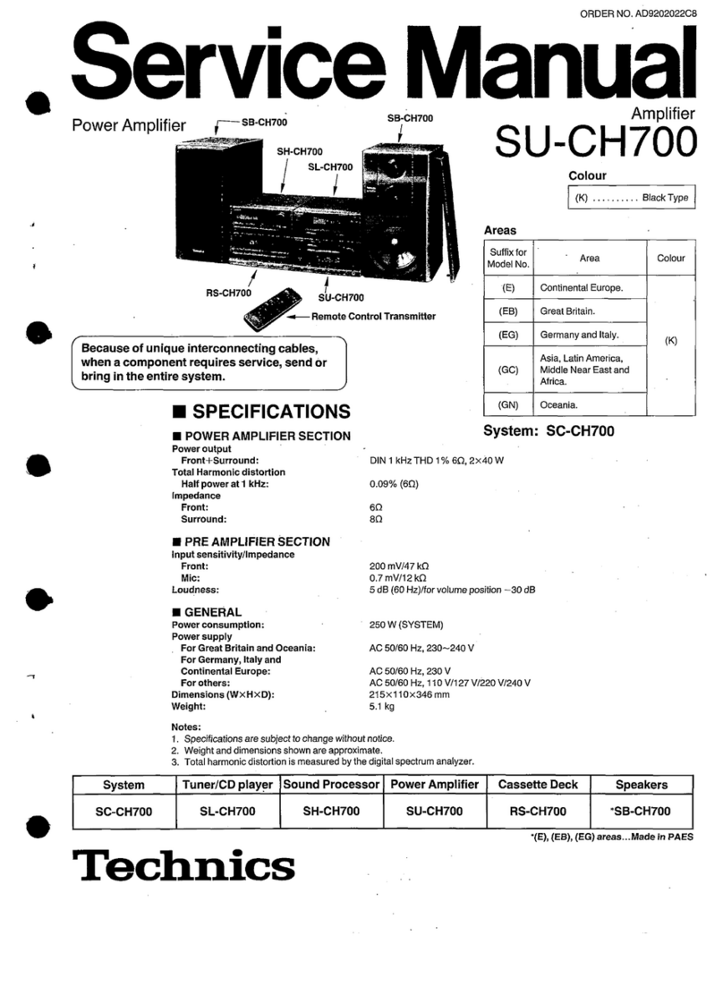
  9. Technics SU-X933 User manual

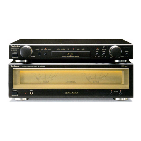
Technics SU-X933 User manual

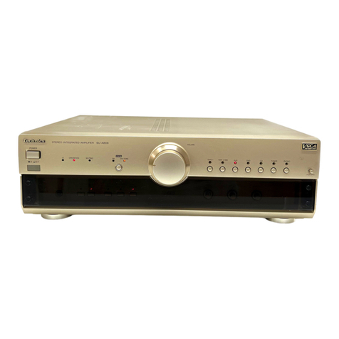
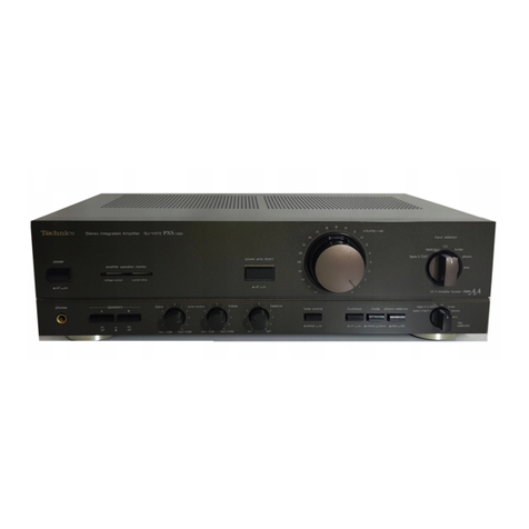
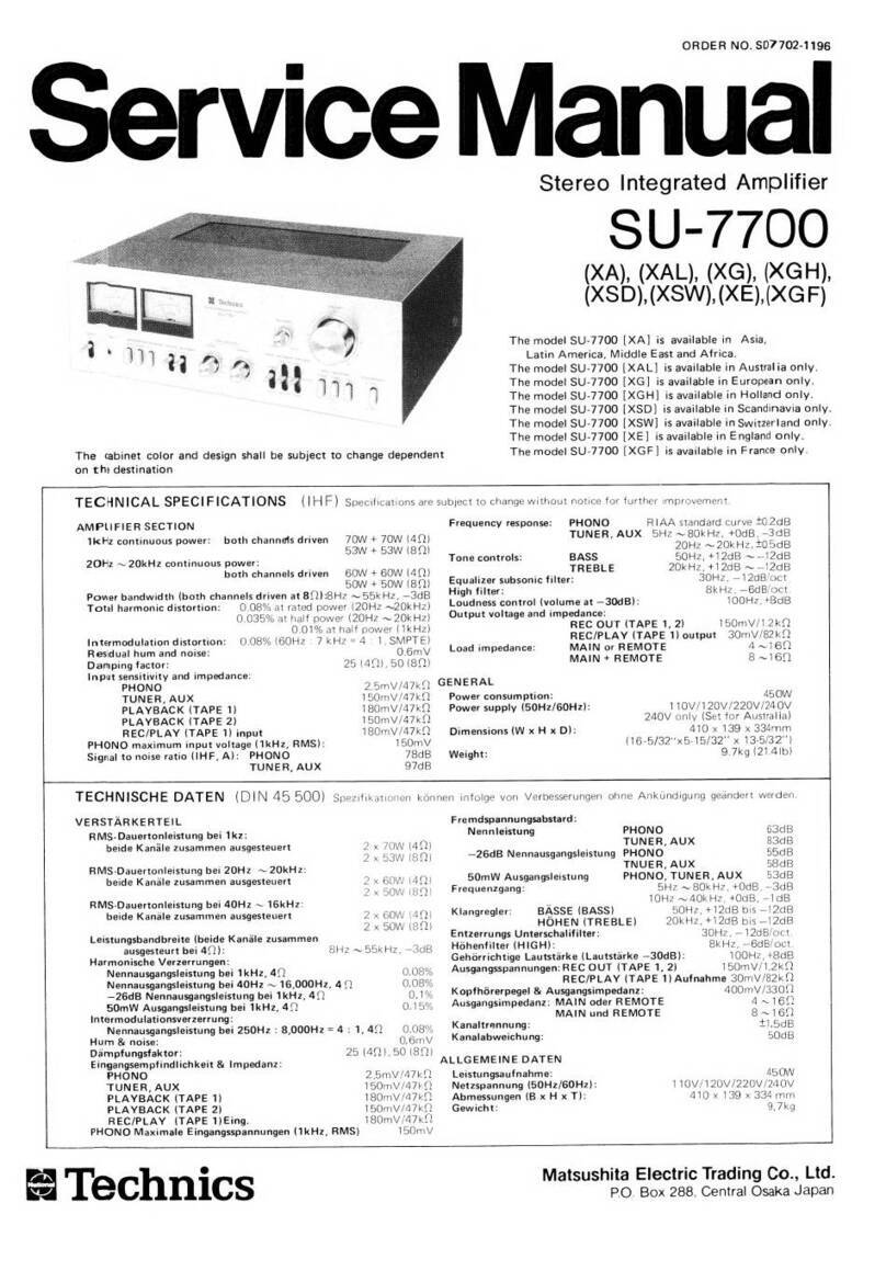
Other Technics Amplifier manuals
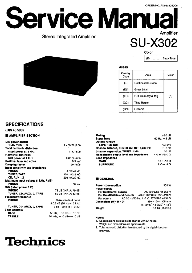
Technics SECH-515-A User manual

Technics

Technics SECH-515-A User manual

Technics SU-X901 - service User manual

Technics

Technics SU-X901 - service User manual

Technics se-ch730 User manual

Technics

Technics se-ch730 User manual

Technics SU-V3 User manual

Technics

Technics SU-V3 User manual

Technics SU-7300 - service User manual

Technics

Technics SU-7300 - service User manual

Technics SU-A808 User manual

Technics

Technics SU-A808 User manual
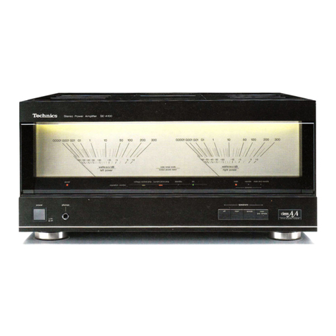
Technics SU-V550 User manual

Technics

Technics SU-V550 User manual

Technics SE-9060 (X) User manual

Technics

Technics SE-9060 (X) User manual

Technics SU-700 User manual

Technics

Technics SU-700 User manual

Technics SU-V55A User manual

Technics

Technics SU-V55A User manual

Technics SU-X920D User manual

Technics

Technics SU-X920D User manual

Technics SU-7700 - SCHEMATICS User manual
Technics

Technics SU-7700 - SCHEMATICS User manual

Technics SU-V900 User manual

Technics

Technics SU-V900 User manual

Technics SU-V505 - service User manual

Technics

Technics SU-V505 - service User manual

Technics SU-8055 X User manual

Technics

Technics SU-8055 X User manual
Technics SU-R1000 User manual

Technics

Technics SU-R1000 User manual

Technics SU-V98 - SERVICE User manual

Technics

Technics SU-V98 - SERVICE User manual

Technics SU-G700 User manual

Technics

Technics SU-G700 User manual

Technics SE-HD505 User manual

Technics

Technics SE-HD505 User manual

Technics SU-X320 User manual

Technics

Technics SU-X320 User manual

Technics SU-C1010 User manual

Technics

Technics SU-C1010 User manual

Technics SU-C01 User manual

Technics

Technics SU-C01 User manual

Technics SU-V303 User manual

Technics

Technics SU-V303 User manual

Technics SU-VX500 - service User manual

Technics

Technics SU-VX500 - service User manual

Popular Amplifier manuals by other brands

Magnat Audio EDITION FOUR Owner's manual/warranty document

Magnat Audio

Magnat Audio EDITION FOUR Owner's manual/warranty document

Inter-m PA-2000A Operation manual

Inter-m

Inter-m PA-2000A Operation manual

Yamaha TX6n owner's manual

Yamaha

Yamaha TX6n owner's manual

Peavey TNT 150 user guide

Peavey

Peavey TNT 150 user guide

Bosch LBB 1903/10 Installation and user instructions

Bosch

Bosch LBB 1903/10 Installation and user instructions

Avocent Emerge DA1200D Installer/user guide

Avocent

Avocent Emerge DA1200D Installer/user guide

Redgum RGi35 operating instructions

Redgum

Redgum RGi35 operating instructions

Cambridge Audio AXA25 user manual

Cambridge Audio

Cambridge Audio AXA25 user manual

Alpine MRP-M200 owner's manual

Alpine

Alpine MRP-M200 owner's manual

Technical Pro H1502UrBT user manual

Technical Pro

Technical Pro H1502UrBT user manual

FMS EMGZ307 operating manual

FMS

FMS EMGZ307 operating manual

Racal Instruments 5601 user manual

Racal Instruments

Racal Instruments 5601 user manual

Valcom V-1094A Technical specifications

Valcom

Valcom V-1094A Technical specifications

Cambridge Audio 851D user manual

Cambridge Audio

Cambridge Audio 851D user manual

QSC 3800 Specifications

QSC

QSC 3800 Specifications

NAD C300 owner's manual

NAD

NAD C300 owner's manual

Rotel RMB-1077 owner's manual

Rotel

Rotel RMB-1077 owner's manual

Peavey Monitor 300 Series operating guide

Peavey

Peavey Monitor 300 Series operating guide

manuals.online logo
manuals.online logoBrands
  • About & Mission
  • Contact us
  • Privacy Policy
  • Terms and Conditions

Copyright 2025 Manuals.Online. All Rights Reserved.

ORDER
NO.
AD8904097C8
.
Manual
Amplifier
SU-X933
Color
(K)...Black
Type
Area
Country
ee
ae
Service
Digital
Integrated
Amplifier
SPECIFICATIONS
(DIN
45
500)
AMPLIFIER
SECTION
Muting
—20
dB
Super
bass
70
Hz,
O~
+10
dB
DIN
power
output
Output
voltage
1kHz
THD:
1%
2x50
W
(8
Q)
TAPE
REC
OUT
200
mV
Total
harmonic
distortion
Channel
balance,
AUX
250
Hz~-6,300
Hz
+1.0
dB
rated
power
at
1
kHz
1%
(8Q)
Channel
separation,
AUX
1
kHz
55
dB
Harmonic
distortion
Headphones
output
level
and
impedance
473
mV/330
Q
half
power
at
1
kHz
0.03
%
(8Q)
Load
impedance
Residual
hum
and
noise
0.5
mV
MAIN
8N~16Q
Damping
factor
30
(8
Q)
SURROUND
8Q~16N
Input
sensitivity
and
impedance
PHONO
3
mV/47
kQ
TUNER,
AUX,
TAPE
200
mV/22
kQ
i
GENERAL
cD
300
mv/15
kQ
Maximum
input
voltage
(1
kHz,
RMS)
Power
consumption
330
W
PHONO
120
mV
Power
supply
SIN
(rated
power
8
©)
For
Great
Britain
and
New
Zealand
==
AC
50
Hz/60
Hz,
240
V
PHONO
73
dB
(IHF,
A,
79
dB)
For
continental
Europe
AC
50
Hz/60
Hz,
220
V
TUNER,
CD,
AUX,
TAPE
84
dB
(IHF,
A:
83
dB)
For
others
AC
50
Hz/60
Hz,
110
V/127
V/220
V/240
V
Frequency
response
Dimensions
(W
x
H
x
D)
360
x
106.2
x
304
mm
PHONO
RIAA
standard
curve
(14-3/16"
x
4-3/16"
x
12”)
+0.8
dB
(30
Hz~15
kHz)
Weight
5.3
kg
(11.7
Ib.)
TUNER,
CD,
AUX,
TAPE
10
Hz~50
kHz
(—3
dB)
Tone
controls
Notes:
BASS
50
Hz,
+10
dB~—10
dB
1.
Specifications
are
subject
to
change
without
notice.
TREBLE
20
kHz,
+10
dB~—10
dB
Weight
and
dimensions
are
approximate.
2.
Total
harmonic
distortion
is
measured
by
the
digital
spectrum
analyzer.
"Technics
Matsushita
Electric
Industrial
Co.,
Ltd.
,
Central
P.O.
Box
288,
Osaka
530-91,
Japan
a
CONTENTS
Page
Page
SEFORE
REPAIR
0.0.2.0
ccc
c
cece
cence
eee
e
teen
en
enees
2
PRINTED
CIRCUITBOARDS
..................00000.
17~21
ROTECTION
CIRCUITRY
0.0.2...
0
cc
cece
cece
eee
eens
2
TERMINAL
GUIDE
OF
IC’S,
ICCESSORIES!.
eA
cetc
korea
etian
ot
Anette
dite
Aanad
2
TRANSISTORS
AND
DIODES
.............0.00000
2000
24
OCATION
OF
CONTROLS
....
0.00...
ccc
cence
een
ence
ees
3
WIRING
CONNECTION
DIAGRAM
..........0000
0000
eee
e
ee
22
SONNECTIONS
0.0...
ccc
cece
eee
eter
cece
eee
e
teens
4,5
DESCRIPTION
OF
FLPANEL
...............00.
000 eee
e
eee
23
ISASSEMBLY
INSTRUCTIONS
.............00
000:
e
eee
ees
6~8
FUNCTIONS
OF
IC
TERMINALS
.............000.000000.
23,
24
SCHEMATIC
DIAGRAM
......0
0.00.0
cece
cece
cece
ee
eee
9~14
REPLACEMENT
PARTSLIST
..............000.
0000s
25~33
LOCK
DIAGRAM
0.0...
0c
ccc
cc
ccc
eee
ence
eect
eee
e
es
15,16
EXPLODED
VIEW
...........0
ccc
c
cece
cece
cece
cece
31,32
#
BEFORE
REPAIR
(1)
Turn
off
the
power
supply.
Using
a
100,
5
W
resistor
connect
both
ends
of
power
supply
capacitors
(C711,
C712,
3300
UF)
in
order
to
discharge
the
voltage.
:
(2)
Before
turning
the
power
supply
on,
after
completion
of
repair,
slowly
apply
the
primary
voltage
by
using
a
power
supply
voltage
controller
to
make
sure
that
the
consumed
current
at
50
Hz/60
Hz
in
NO
SIGNAL
mode
should
be
shown
below
with
respect
to
supply
voltage
110
V/127
V/220
V/240
V.
Power
supply
voltage
AC
110V
AC
127V
AC
220
V
AC
240
V
Consumed
current
50
Hz
|
100~500
mA
70~470
mA
50~250
mA
40~240
mA
Consumed
current
60
Hz
|
97~476
mA
68~457
mA
49~244
mA
39~236
mA
#
PROTECTION
CIRCUITRY
The
protection
circuitry
may
have
operated
if
either
of
the
following
conditions
is
noticed:
*No
sound
is
heard
when
the
power
is
switched
ON.
“Sound
stops
during
a
performance.
The
function
of
this
circuitry
is
to
prevent
circuitry
damage
if,
for
example,
the
positive
and
negative
speaker
connection
wires
are
“shorted”,
or
if
speaker
systems
with
an
impedance
less
than
the
indicated
rated
impedance
of
this
unit
are
used.
If
this
occurs,
follow
the
procedure
outlined
below:
1.
Switch
OFF
the
power.
2.
Determine
the
cause
of
the
problem
and
correct
it.
3.
Switch
ON
the
power
once
again.
Note:
When
the
protection
circuitry
functions,
the
unit
will
not
operate
unless
the
power
is
first
switched
OFF
and
then
ON
again.
ACCESSORIES
@AC
power
supply
COP
2...
eee
cece
renee
e
eens
1
Configuration
of
AC
power
supply
cord
differs
according
to
area.
e@Attachment
AC
plug
..........
0.
ccc
eee
ee
eee
eens
1
SJA190
.........-
For
(GN)
area
only.
SJP9215...For
(GC)
area
only
SJA188
..........
For
(EB)
area
only.
RJAO004
........
For
(GC)
area
only.
SFDACO5E03_....For
others.
m
LOCATION
OF
CONTROLS
eFront
panel
[1]
Power
switch
(POWER)
[2]
Voiume
level/balance
indicator
(BALANCE/VOLUME)
[3]
Volume-level
indicator
[4]
Muting
indicator
(MUTING)
[5]
Volume
control
(VOLUME)
[6]
Input
selectors/indicators
eRear
panel
PLAY
BACK
TAPE
(REMOTE
OUT)
TO
DECK
REC
ouT—
(REMOTE
IN)
TO
TUNER
EXT
LoutpuT
—
TUNER
GND
Audio
muting
switch
(MUTING)
Balance
controls
(BALANCE)
[9]
Tone
controls
(BASS/TREBLE)
Super
bass
control
(SUPER
BASS)
[11]
Surround-sound
switch
(SURROUND)
[12]
Headphones
jack
(PHONES)
COOLING
FAN
[SURROUND
-
SOUND
—
SPEAKERS
Co
~AC
IN
TURNTABLE
4
SYNCHRO-REC
tei
a
cD
SYNCHRO
TAPE
VOLTAGE
SELECTOR
(For
(GC)
area
only)
TO
DECK
(Except
[EG]
area)
*Phono
input
capacitance
is
about
270
pF
for
EG
area
(about
100
pF
for
other
areas).
m@
CONNECTIONS
sciedTes
Turntable
SYNCHRO
REC
(not
included)
Tuner
OUTPUT
(not
included)
QD
QD
A
0
é
:
(See
below.)
Re)
RH
OHUROY
MOR
i
cen
MN
{J
REMOTE
contro.
Graphic
INPUT
OUTPUT
equalizer
®
@
(not
included)
i
“GND”
terminal
of
the
amplifier
This
terminal
is
for
use
with
a
turntable
which
has
a
ground
wire.
“EXT”
terminals
of
the
amplifier
When
these
terminals
are
not
in
use,
be
sure
to
insert
the
shorting
pins
(included).
Connection
diagrams
shown
are
for
connections
to
a
Technics
hi-fi
component
system.
Make
connections
in
the
numbered
sequential
order.
[1]Connect
the
stereo
connection
cables
(included
with
the
turntable,
tuner,
graphic
equalizer,
compact
disc
player
and
cassette
tape
deck).
[2|Connect
the
L-type
cables
(included
with
the
turntable,
compact
disc
player,
graphic
equalizer
and
cassette
tape
deck).
Note:
Connect
the
L-type
cables
included
with
a
compact
disc
player
as
illustrated
below
in
either
case:
eWhen
a
graphic
equalizer
does
not
have
the
remote
control
terminals.
«When
a
graphic
equalizer
is
not
used
in
combina-
tion
with
these
components.
Compact
disc
player
REMOTE
q
Cassette
tape
deck
y
OUTS
REMOTE
CONTROL
Turntable
(not
included)
[3]Connect
the
flat
cables.
[3-t]
Connect
the
3-core
flat
cable
Household
AC
outlet
(included
with
the
tuner).
oe
[3-2]
Connect
the
3-core
flat
cable
Tuner
CONTROL
AC
OUTLET
(included
with
the
cassette
tape
deck).
AMPLIFIER
—\
[ae
(not
included)
~AC
IN
[4]Connect
the
AC
power
supply
cords.
Connect
this
cord
only
after
all
other
cables
and
cords
have
been
connected.
Notes:
1.
The
configuration
of
the
AC
outlet
and
AC
power
supply
cord
differs
according
to
area.
ae
Except
[EG]
area)
-
2.
Connect
the
AC
power
supply
cord
included
with
a
He
(
compact
disc
player
to
the
AC
outlet
of
the
[3-2]
4
amplifier
as
illustrated
below
in
either
case:
¢When
a
graphic
equalizer
does
not
have
the
AC
Graphic
equalizer
AC
OUTLET
outlet.
(not
included)
When
a
graphic
equalizer
is
not
used
in
combina-
tion
with
these
components.
Amplifier
Compact
disc
player
AC
OUTLET
AC
OUTLET
(not
included)
~AC
IN
LJ
Gat
Compact
disc
player
AC
OUTLET
)
~AC
IN
(e2)
Ly;
a
a
|
@
About
the
AC
outlets
of
the
each
components
Do
not
connect
video-related
equipment
(such
as
a
TV,
etc.)
to
the
AC
outlets
of
these
components.
(These
outlets
are
especially
for
audio
equipment.)
Also
do
not
exceed
the
indicated
power
ratings
when
connecting
to
these
outlets.
°
“SWITCHED”
outlet
(For
tuner)
Power
is
controlled
by
the
power
switch.
¢
“UNSWITCHED”
outlets
(For
amplifier,
compact
disc
player,
graphic
equalizer)
Power
is
always
available,
regardless
of
power
switch
setting.
m@
DISASSEMBLY
INSTRUCTIONS
|
Removal
of
the
Cabinet
Removal
of
the
Front
Panel
Procedure
1—2
Cabinet
(Bottom
Side)
&
13]
1.
Remove
the
3
screws
(@~®).
2.
Remove
the
flat
cable
(J501).
3.
Remove
the
front
panel
in
the
direction
of
the
arrow.
Remove
the
6
screws
(Q@~@).
Removal
of
the
Power
Switch
P.C.B.
Procedure
152-3
Power
Switch
Front
Panel
How
to
remove
the
flat
cable
a
Pull
out
the
flat
cable
while
pressing
the
connector.
1.
Remove
the
power
switch
knob
by
pushing
it
from
behind
the
front
panel.
2.
Remove
the
2
screws
(@,
@).
Removal
of
the
Volume
P.C.B.
Ref.
No.
Removal
of
the
FL
Drive/Tone
4
Amp
P.C.B.
and
Volume
P.C.B.
1.
Remove
the
1
knob
(@).
2.
Remove
the
1
nut
(®).
Procedure
Removal
of
the
FL
P.C.B.
1.
Remove
the
3
knobs
(Q@~®).
3.
Remove
the
2
screws
(Q,
®).
2.
Remove
the
3
nuts
(Q@~@).
3.
Remove
the
5
screws
(@~@®).
tie
Connector
ae
B:
16mm
C:
longer
than
18mm
Use
a
wrench
of
the
dimensions
shown
in
the
illustration
above
to
remove
nuts.
Removal
of
the
Operation
Switch
|.
Ref.
No.
Removal
of
the
AC
Outlet/AC
IN
Ref.
No.
Removal
of
the
Fan
Motor
Ref.
No.
Removal
of
the
Power
P.C.B.
6
P.C.B.
9
10
Transformar
Procedure
Procedure
Procedure
1524-5
1>6
mm
110
3]
Kf
S|
=<
Operation
Sutch
Lpe
:
7
,
AP
a
A
|
(
Iw
AC
Outlet
/AC
IN
PC.B-
1.
Remove
the
3
screws
(Q@~®).
2.
Release
the
4
claws.
Release
the
4
claws.
1.
Remove
the
1
flat
cable
(J701).
2.
Remove
the
4
screws
(@~@Q).
Rear
Chassis
.
Pull
out
the
1
connector
(J207).
.
Release
the
3
claws.
.
Insert
a
screwdriver
at
the
root
of
the
cooling
fan.
Force
it
out
of
the
motor
shaft.
.
Remove
the
motor
cover
by
used
©
screwdriver.
.
Remove
the
motor
from
the fan
casing.
.
When
mounting
the
motor
fan,
align
the
fan
casing’s
projection
with
the
hole
of
the fan
motor.
Cooling
fan
1.
Remove
the
6
screws
(Q@~@).
2.
Remove
the
1
connector
(J204).
Fan
case
Projection
Fan
motor
Regulator
Transistor
1.
Unsolder
the
power
IC
or
regulator
transistor.
2.
Remove
the
3
screws
(Q@~®).
eWhen
mounting
the
power
IC
or
regulator
transistor.
Apply
silicone
compond
(SZZOL15)
to
the
rear
side
of
.
4.
Remove
the
3
screws
(@~®).
power
IC
or
regulator
transistor.
5.
Remove
the
main
P.C.B.
in
the
direction
of
the
arrow.
2
3
4
5
6
7
8
9
10
ES
crono
EQ
AMP
/
INPUT
SELECTOR
CIRCUIT
VOLUME
CIRCUIT
Q202,
203
GND
@
2SDI450QRSTA
Cilo0
108
12
Ha
SWITCHING
VR6EOI
For
CEG)
area.
ae
(
SURROUND
ON/OFF
)
(VOLUME
1
ao!
R102
390
50V3.3
:
ENSOPER
|
PHONO
‘e
|
aa
ait
aN
difference
@:
.
poy
Ber
|
B83
S3S88T
2
180K
signal
beat:
GA
Eooy
célé
R638
ie
REC
OUT!
Se
ga
220P
TAPE
oe
ziah
(C203
RIS6
IK
AN6554F
eee
ow
8
AN6558F
MIXING
/
2a,
PHONO
EQ
AMP
PHASE SHIFT
23
1c602
RISB
IK
MN40308
AUX
Ott
b
LOGIC
(OR)
teal
)
|
RI01
390
eey;
|e
wee
B
Lots
E
23
R236
6.8Kf
=zN
cD
Oat
c
88
ws.
52
of.
~—S
y
ZN
Phono
signal
on
Sree
For
(EG)
area.
(Lch)
83
0.022
0.0068
Lich
antes
{+}
.
|
RI51.470
|
R606
10K
PHONO
(Q)“pedeenpararept
5
be
Bey
Set
|
Be
O—G—O
0-0
Somes
z
(ie
es
RS
[REC
OUT
Q-sort
83
7
a201
uae
1K
e8T
aid
3
Se
ey
MN40138
TAPE
a
e:
oy
LOGIC
RI55
IK
x
(F-FLOP)
Le
aveacnG—
Sit.
a
My
:
5S
s
S
Cc
se
2
ati
RIS7
IK
ha
C214
AUX
Oa
et
b
«
254.7
18g-!
%
R605
10K
poe
|
:
L602
1.2p
R235
6aKy
2
cD
Wt
c &
38
Q20!
eal
¢
b_a
2S|AIZO9AQSTA
SWITCHING
For
(EG)
area.
TCOI64N
CONTROL
INPUT
SELECTOR
Recording
signal
~~
|
I
CONTROL
1
(TO
TUNER’
R661
D620
15K
MAIGSTA
REMOTE
OUT|
:
4203
E
(TO
TAPE)
D6I4,615
617,618
R640
470
0614.4
(TAPE)
SWITCHING
UNG7SRP-LS
‘e—
(TUNER
REMOTE
)
R641
470
0615
4%
1
AUX)
RIS9TK
D616
ad
TUNER
LD-
OOIVR
R645
220
0616
aw
(cD)
ey
(TAPE)
OH
r
OUTPUT
aOpret
R643
470
0618
ae
(
PHONO)
EXT
‘S,
L751
100,
[Es
INPUT
skeoz
i
7
co
|
25.
{
@)
Sel
i
()
R
ch
SYNCHRO
REC
F
eae
ae
MAIN
CIRCUIT
TUNER
C)
h
FAN
C)
i
iho
ea
tel
[OUTPUT
°
.
esltsivs
EXT
Bey
8oT
837
L
input
eee
ie
Tepe
eee
ae:
Except
CEG)
FE}
neut
/
output
TERMINAL
CIRCUIT
=9=
—10-
11
12
13
FL
ORIVE
/
TONE
AMP
CIRCUIT
14
15
17
19
0606611
MAI65TA
TAIRE58
5.6K
I1c301
TC9I77P
R656
1.2K
R659
56K
Q605,609
UN42II1TA
SWITCHING
(REC
/
REMOTE
}
Q6o!
2SAI3Z09AQSTA
SWITCHING(
REMOTE
Q609
C695
0.01
IR626_
221
R627
22K
2K
100p
AAT
L618
100p
|
-4
R64
L6I7
100
L619
100p
L620
(b
—-—
FL6O!
(
RSLOOI3-F)
FL
DISPLAY
63
$8
so
SI
$2
G2
$3
$4
Gi
SS sé
S7
ooo
CO).
OM
OM)
-B-)
(9)
OOO)
@)—)
;
ag
3
ie
0613
283
SBS
MA4056MTA
ze
5
9604
of
Ms
Pay
gee
bos
2SC33IIAQSTA
83
8
SWITCHING
(TURNTABLE
STOP)
f
ed
Q604
ov
ov
i).
Q605
O7V
3
375
6.2V
g
‘
io
6
av
=
S[
xl
S|
&
x)
UX
8S 83
8
Soh
24a
tt
ttt
8
BF
se
8
3
98
p60!
|
Leo!
¢
2)
2]
2]
&
Fe
gx
—
S
MaAl65TA
|
100y
=
R6I3_
220K
|_|
62v
>
s
ray
ae
ek
Tyg
2d.
s
ssi
[ss
Lie
sv
bie
7vt-i2
av}-i2
evf-205vh-203
Lieavbiervbea.ivis
av
[6
2v
g62v
je
2v
ge
ev
forv
iene
nedt
des
€)—-@)—6)
-)-)-8)
6).
6)
6)
69)
6)
6)
6)
0
49)
09)
6)
0)
49) 49)
eo
83
8S
a 8
»
&
8
%
6
&8
&
$
|§
[8
BP
FE
I
8s
&
0,
o
key
return
34,
md
Be
ake
iS
|
e
SEGMENT
OUT
ay
b=]
---0V
Se
eS
~|———
5V/0.5ms.
DIV
~2ayv
Ic6ol
Py
KEY
20V/Ims.
DIV.
VOLUME
20V/
ims.
DIV
GRID
OUT
RETURN
IN
KEY
SCAN
OUT
ENCODER
x.
A
as
R670
68
Q607
oS
I+
Lod}
/
SS
6.2V
Ov
“Fe.2v
Tov
ave
avye2v
J605A
h
7
(Sf)
Se
é
ray,
b~|
~20.8V
a
BQ]
ox
sx
gx
ZX]
ow
3S
2s
2s
22
I
«2
+_%
L8s
Q602
®
4
a607
as
2SC331IAQSTA
\
FL
DRIVE
(Hy
O
e
gq
ohi
Aa
MY
3
J604A
5V
_
~y
Oo
f
ov
(7)
5V/0.5ms.
DIV
ov
6
av
{0k
p-
@
C)
a610
45>
9)
+
(5).
6.2V
6.2V
J603A
(5)
e
OF
q
Or
¢
ley
5
-24.1V
C)
a.
R690
1K
o
©
<
Os
<
a
Vv
FOV
‘OV
me
2.6V
6)—@)
sy
0
sy.co
@)
deb
REM
()
LED
DRIVE
R673
22K
R650
56K
C698
0.001
FH
ey
=
a
rs)
VW
R664
IK
Role
2
(3)
TEST
@)
Vss
=(&)
OSCIN
D614
MAI65TA
+p
Wie
al
Q602,603,610
UN42
IITA
SWITCHING
1c60!
LC6554D
-
3230
MICRO
COMPUTER
14.6V
c—
S6O0IA
(SURROUND
)
ATTENUATOR
14.6V
UN4211TA
R3I7
22K
R301
10K
20
2
R303
10K
C312
_25V3.3
-
C316 SOV!
—Hy
14
4V,
abcde
ab
Q501,502
2SC3II4STU
MUTING
Q503
2SAI309AQSTA
MUTING
CONT.
(d
sacatatate
R506
c524
C506
RS34
-
33K
3033
504
teyee
NRK
oy
"R508
ovexs
|
2SAIZOSAQSTA
*e5i2
i)
1K
88
Sm]
MOTOR
ORIVE
20K
-14.2v
8
S/
0502
=
@505
&
1
32
28C331|
cay
“2
eet
3s
MOTOR
DR
25V4.7
gz
=
ye
R521
beh
1c70l
“Ny
10K
|
France
AN78LO6
aso4
(7)
RPA
REGULATOR
14.6V
fice
ss
“14
ay
|
ICc70!
Q703
c
ba
Anros
2SDI762EF
an
6.2V
10.3V
72W
120
R
f
3
SpuLAroR
o
Ssar
©
52
s
of
Co
gs
©
x
3
S
x
oO
2
&
9701
S
5
$
S
UN4211TA
$
SWITCHING
5
is
F3
o
oO
=
S
a
Ss
eae
a
8x
oe
En
othe
2
:
9702
00
08
08
oN
Ao704
2SA684QRS
53
58
Sot
MAI67TA
REGULATOR
a
_21
22
23
24
25 26
27
28
29
m@
SCHEMATIC
DIAGRAM
(Parts
list
on
pages
25~30)
|
~——Phono
signal
(Lch)
1302
3x
R30
|
Vie.
47K,
nie
Svs
i
Saker
(This
schematic
diagram
may
be
modified
at
any
time
with
the
development
cnet
t
Sox
bd
4
of
new
technology.)
3
Bs 28
rae
avd
at
0302
|
in
2
leo.
Notes:
7
D301~
304
Eee
ae
eS1:
Power
switch.
>
scene
eS2:
Voltage
selector
switch
in
“220
V”
position.
Lé
O-~O
*
(110
V/127
V/220
V/240
V)
Sige
sik
ov
ov
Yow
8
For
(GC)
area
only.
b
Wee
-
-
eS601A:
Surround-sound
switch.
ONS
ze
2s
ee
Gear
0304
Q301,302
©S601~604:
.
BES
C302
.
2SC331|AQSTA
S610:
Input
selector
switches.
SUPER
CRASS
AM
ieee
:
PHONO,
S602:
TUNER,
S603:
AU
ais
S604:
TAPE,
S610:
CD
aa
©S607,
608:
Balance
control
switches.
Pa
let
(S607:
Leh,
S608:
Rch)
ee
ese
eS609:
Audio
muting
switch.
€325,
SOV!
meses:
GD
Phono
signal
line
=
=<"
Recording
signal
as
wz)
Phase
difference
signal
mum
Super
bass
signal
34a
47k
—_
>=
Positive
voltage
line
-~<<_
>-Negative
voltage
line
ee
=
Rice
fae
T90F
|
c308
160?
J
cap
covet
f
(Ea
ets
Bs
:
ol
ge
*
Indicated
voltage
values
are
the
standard
values
for
the
unit
measured
by
SV13102B
3a.L85
R324.
220K
gose
TSE
tak)
aan
the
DC
electronic
circuit
tester
(high-impedance)
with
the
chassis
taken
as
me
ot
.
.
Siac
oe
Ee
Bls
poser
ey
standard.
Therefore,
there
may
exist
some
errors
in
the
voltage
values,
depending
on
the
internal
impedance
of
the
DC
circuit
tester.
e|mportant
safety
notice:
Components
identified
by
A\
mark
have
special
characteristics
important
for
safety.
When
replacing
any
of
these
components,
use
only
manufacturer's
specified
parts.
pale
=
ee
eT
lea
ee
eee
oes
4501
Ks03
503
505
«R533,
“SII
;
oO
ee
el
oa!
Dene
ne
“Caution!
R328
wx
Ow.
i
B38
C326
S50VI
TONE
AMP.
OOP
'ev22
12k
0047
>
‘|
>
0
:
,
Lah
;
@
|
IC
and
LSI
are
sensitive
to
static
electricity.
oi
0)
oh
%
(|
Secondary
trouble
can
be
prevented
by
taking
care
furing
repair.
‘
iS
6
|
*Cover
the
parts
boxes
made
of
plastics
with
aluminum
foil.
L502
:
te
osoa
levee
‘Tek
7
|ie'to
doat
For
CEG)
area,
©
Ground
the
soldering
iron.
2salsosaasTa
LN
xsi2
0
ia
1
Y
*Put
a
conductive
mat
on
the
work
table.
MOTOR
ORE
Sarena
*Do
not
touch
the
legs
of
IC
or
LSI
with
the
fingers
directly.
5
Q505
Bla
|
88
38
|
38
2SC33IIAQSTA
ge
|
FE
(Sel
ssl
HEADPHONES
BE
MOTOR
DRIVE
83
¥8s¥
7
POWER
Power
Source
For
(GC)
area.
|
a
9505
Seto,
|
om
|
SWITCH
ste
aud
ENOEN
Wee
“pe
iy
}
CIRCUIT
ae
Py
mane
a
188
Ssl
|
J
gs
fro
33g
@
pe
LL
MY
(OMCONNC)
bod
*
ox
M501
ch
Rch
Leh
Rech
Be
Beg
Lspeakers~
-SURROUND—
é5
@)
Be
eee
oor
A
(8160
)
SPEAKERS
7(
wf
20
RE
a
(8~16Q)
@))
For
(EB)
area.
!
s
2
GiRGE
een
8
5:
G2)—O~_9
i
Ac
ouTLeT
|
rd
.
et
=
ii
oe
eS
rte
(
SWITCHED
)
=
Be.
s
R
(8)
oR
TI
es
<f
el oe
eee
I
:
g
2
1
For
CE,E5,EG
5
:
=
al
ie
fie
ES
g
4
ON
0
—{
2)
@0
A
|
io
8
AC
OUTLET
1
A
%
@
2
a
(
UNSWITCHED)|
5
Kee
“3
pe
A
eS
4
AC
OUTLET
ook
1
(UNSWITCHED)
,
5
bs
1
Kore
A705
|
“
MAI67TA
MAI67TA
2SBI
(85EF
1
3
|
C|
A
REGULATOR
>
+
()}—-€3)
@3)
<
Bene
es
i
a
a)
AC
220V---CE,E5,E6)
AC
240v---
CEB,GN)
(50
/60Hz
)
o
AC
110/127
/220/240V
AC
IN/
AC
OUTLET
(50/60Hz
}
al
TERMINAL
CIRCUIT
-13—
UD
CEE
Be
DD
CEE)
m@
BLOCK
DIAGRAM
AN6558F
TCOI64N
Ce
pl
PHONO
EQ
AM
\
28
iia
INPUT
T
M5238P
jc.
2031)
Q
AMP
po
NPUT
SELECTOR
Pico]
MIXING(PHASE.
DIFFERENCE
8
[Riza
|
I
X1
[x2 [x3
[x4
[xs
[x6
x7
|
[PHONO
r
PHASE
SHIFT
er
aren
|
[TUNER
O
)
xl
5
rl>
t
Soto
|
1
[co
Pee
=
|
bau
0504,505
Om
0
|
|
ANGS5S4F
=
D501
oa
pee
d
Cn
Cc»)
&®)
el
p=
fp
|
Ee
MIXING/SURROUND
AMP
|
aaa
(3)
x2
|
|
(
)
indicates
pin
No.
of
_
c
SO
TUNER
e—_
°
\
right
channel.
(M)
Fan
MoTOR
0502
i
Sete
25
Sa
(4)
1
x3
|
|
7
co
0
|
ol
2,
!
—44
!
@|
—
ey
Lxal
|
}
&
“bee
eee
Reh
M4
B
aa,
O
|
Pei
as
by
23
|
!
4a
Yul
‘elf
|
on
220!
Lech
pares
|
1
G8)
CB)
[?
Switching
Open
=|
a
L
e
:
contro!
SURROUND
PLAYBACK
(}
ee
I
|
CB
sea
PHASE
SPEAKERS
:
—{-
y
7
(
SURROUND
)
OIFFERENCE
SIGNAL’
TAPE
21
im
[Reh
]
@
Renal
®
(sy
st
xe}
|
!
dt
tH
tren]
REC
ouT
Q———
!
L
4
TC9I77P
ry
F
20
|
bw
9
N
6552
3
ch
Hd
of
p-—-—4
in
AN6558F
ATTENUATOR
BUFFER
AMP
LOW
tox?
juz)
(VOLUME
CONTROL)
B®)
anescer:
Tar
‘5
BUFFER
AMP
[pa
eo
et
i
a
a"
s
J
.
hd
i
A
js
_J
,
\
!
|
Pana
hf
7
a
|
Cama
4
3
(5)
O
2h
>
M7)
&
Q6
2
eS
ed
l2n614
24
[>
=
a
'
HEADPHONES
FouTPUT
(-O
-
l
EXT
Es
leineur
O
I
Power
|
on/off
|
Bass
i
\
\
Q651
D620
Q601,
609
VR601
I
Suppr
L
ths
soaks
VOLUME
boss
6
D
CONTROL
ENCODER
=
control
a
(TO
TUNER)
ve
tel
|
oo-{-
2.48
|
C8)
930119302
)
Vv
(Ve
lee
ey
|
I
Io
otorr
St
|
!
|
42
Q503
yo
rger
.
48)
aint
REMOTE
1814
1
tooo
|
uting
950!
-————
REMOTE
OUT
]
le
control
(9502)
{|
REC
SIGNAL
Q605
MN4030B
ue!
(TO
TAPE)
ues
!
‘
fi
eae
MN
40138
Te
E
(EG)
xcept
G
SYNCHRO
l
INTERFACE
|
GB) CB)
FSi
ae
pre
(
TAPE)
oe
|
|
|
TO
TAPE
I
46
348
YF
j
3
LS!
pol
tO
Sta
aS
See
Oa
ete
et
4
r
(
POWER
|
Coe,
wee
a.
eee
:
Ss,
ee
:
:
suPPLY)
|
turn7as.e
[]
29
os
&
5
2
$
a
5
LC65540-3230
5
!
i
E
ic
P32
ple
eee
!
MICRO
COMPUTER
SYNCHRO
REC
6
AN78LO6
For
(EB)
area.
SB
te
TE
ie
eee
EN
SYNCHRO
STRAT
4
sy.co
w
2
°
=
L
——
CD
|]
*,
Sta
Sey
fe
ars
°
Pe
ae
me 2S
<
-
os
EB
e
&
2
2
2
!
ac
outcet
!
Gi
o
>
On Om
=
=
=
~-
S 5
Boseoe
co
o
5 S
J
(switcHeo)
|
13
fiz
Jair
[to
5
32
|
,
|
703,070!
o.
§.-\b
Sh
ee
eee
a
|
|
seo3
|
se6oo
|
séos
i
[j-
a
eae
(MUTING
)
(RIGHT
|
|
Pale
Petre
la
a]
2)
|
al
52
z|
oo
!
s6o7
|
.
3
2)
Lo
saya
poees
(cD)
(LEFT)!
2a
lee
ie
eee
a
|
9702,0713
|
p707~
710
From
power
transformer
;
NS
|
|
¢}
«0
hk]
@
|
|
RECT.
FL
Display
ING,
ae
|
©!
©
o|
©
L
gx
|
o|
a
al
a
|
~
—
F
|
|
|
|
X60
|
$602
\ \
Q704,0702
HeNTUNER)
|
|
|
aN
|
|
|
°
Notes
|
!
|
|
Soin
Pe
a
|
$601
|
l
—>—
=
PHONO
SIGNAL
(PHONO)]
0602,
603,610
D704
0705
For(E,£5,EG)
areas.
!
1s
NC
| |
|
Q701
++
|
rc
a
=>
=MAIN
SIGNAL
|
|
|
|
|
|
I
;
H
L——__i__4___
|
TO
FL
DISPLAY
|
pipers
|
zz>
:PHASE
DIFFERENCE
SIGNAL
I
(ed
eet
Nt
4
[ele
a
pt
et
ma
|
(UNSWITCHED)
|
Le
ee
ee
ee
4
KEY
MATRIX
CIRCUIT
INPUT
SELECTOR
IND.
ees
L
4
=5
—
—16—