Technisonic Industries Limited A711 L-Series User manual
ACCESS/A
TM
AUDIO CONTROL
SYSTEM
MODEL: A711 L-Series
Installation Manual
TiL Document No.
09RE416
Rev. N/C
January, 2011
Technisonic Industries Limited
240 Traders Boulevard, Mississauga, Ontario L4Z 1W7 Tel: (905) 890-2113 Fax: (905) 890-5338
www.til.ca
ACCESS/A A711 L-Series Installation Manual 09RE416
Technisonic Industries ltd. Copyright 1996, 97, 2010, 2011 BY TiL ALL IGHTS ESE VED ii
REVISIONS
Revision Page Description Date Approved

ACCESS/A A711 L-Series Installation Manual 09RE416
Technisonic Industries ltd. Copyright 1996, 97, 2010, 2011 BY TiL ALL IGHTS ESE VED iii
CAUTION
This unit contains static sensitive devices. Wear a grounded wrist strap and work at a static-safe
workstation when handling internal printed circuit boards.
WARRANTY INFORMATION
The Model A711L Audio Controller is under warranty for one year from date of purchase. Failed units
caused by defective parts or workmanship should be returned for warranty service to:
Technisonic Industries Limited
240 Traders Boulevard
Mississauga, Ontario L4Z 1W7
Tel: (905) 890-2113
Fax: (905) 890-5338
TRADEMARK INFORMATION
ACCESS/A, ACCESS/D, ACCESS/R & ACCESS/F are all trademarks of Technisonic Industries Ltd. All
rights reserved.

ACCESS/A A711 L-Series Installation Manual 09RE416
Technisonic Industries ltd. Copyright 1996, 97, 2010, 2011 BY TiL ALL IGHTS ESE VED iv
TABLE OF CONTENTS
TiL DOCUMENT 09RE416
SECTION 1 GENERAL DESCRIPTION
1.1 Introduction ..................................................................................................................1-1
1.2 Description...................................................................................................................1-1
1.3 Purpose of Equipment .................................................................................................1-2
1.4 Model Variations ..........................................................................................................1-2
1.5 Technical Summary.....................................................................................................1-5
1.6 System Limitations.......................................................................................................1-7
SECTION 2 INSTALLATION INSTRUCTIONS
2.1 General ........................................................................................................................2-1
2.2 Equipment Packaging Log...........................................................................................2-1
2.3 Wiring Requirements ...................................................................................................2-1
2.4 Audio Panel Installation & Drawings............................................................................2-2
2.5 Kit Contents...................................................................................................2-15
2.6 Pin Connections and Locations ....................................................................2-16
2.7 Headphones..................................................................................................2-20
2.8 Microphones .................................................................................................2-21
2.9 PTT ...............................................................................................................2-21
2.10 Main Power...................................................................................................2-21
2.11 Backlighting Power........................................................................................2-21
2.12 Annunciator Dimming....................................................................................2-22
2.13 Ground..........................................................................................................2-22
2.14 Storage.......................................................................................................................2-22
2.14 Post Installation Adjustment Locations......................................................................2-23
2.15 Post Installation Adjustments.....................................................................................2-24
2.16 Product WarrantyTerms.............................................................................................2-29

ACCESS/A A711 L-Series Installation Manual 09RE416
Technisonic Industries ltd. Copyright 1996, 97, 2010, 2011 BY TiL ALL IGHTS ESE VED v
LIST OF TABLES
1-1 A711L General Specifications .......................................................................................... 1-4
LIST OF ILLUSTRATIONS
1-1 A711L Audio Control - General View................................................................................ 1-3
2-1 A711L Outline Drawing..................................................................................................... 2-3
2-2 System Installation Drawings- Pilot/Co-Pilot Wiring......................................................... 2-4
2-3 System Installation Drawings- COM1-COM4 Wiring....................................................... 2-5
2-4 System Installation Drawings- COM5-NAV1 Wiring........................................................ 2-6
2-5 System Installation Drawings- NAV2-NAV5 Wiring......................................................... 2-7
2-6 System Installation Drawings- NAV6-NAV8/CST/Aux Wiring.......................................... 2-8
2-7 System Installation Drawings- Passenger Wiring............................................................ 2-9
2-8 System Installation Drawings- Alternate Passenger Wiring........................................... 2-10
2-9 System Installation Drawings- Power, Dim & Alerting Wiring........................................ 2-11
2-10 System Installation Drawings- Direct Input/Special Function Wiring............................. 2-12
2-11 System Installation Drawings- Reserved Wiring............................................................ 2-13
2-12 System Installation Drawings- Special 6-Place Passenger Wiring................................ 2-14

ACCESS/A A711 L-Series Installation Manual 09RE416
Technisonic Industries Ltd. Copyright 1996, 1997, 2010, 2011 BY TiL ALL RIGHTS RESERVED Page 1-1
SECTION 1
GENERAL DESCRIPTION
1.1 INTRODUCTION
This publication provides operating and installation information on the Model A711 L-series,
ACCESS/A Audio Controls manufactured by Technisonic Industries Limited. For convenience, it
is referred to as the “A711L” in the manual. This unit is designed to provide high performance
cockpit audio control in high noise installations. The unit is plug and pin compatible with the
ACCESS/A family format, to allow fleet wide compatibility with all ACCESS/A installations, with
the following limitations: The A711L has its extra functions assigned to the “Alerting”
connector, and can also have 3-tone alerting as an internal option. These connections are slightly
different than a standard A710/711 unit, and to prevent any airframe problems, the alerting
connector has different locks on the A711L, to make it impossible to connect it to an airframe
wired for default A710/711 functions. If an existing installation had no alerting connector wiring,
then it can be used without difficulty, but note the installation issues regarding annunciator
dimming. The A711L comes ONLY in a 28V panel backlight configuration.
1.2 DESCRIPTION
This high power audio controller delivers at least 332 mW of audio into 150 ohms at less than 2%
total distortion to the pilot and co-pilot positions simultaneously. It can deliver lower output powers
into 300 and 600 ohm headsets. The pilot’s position may also be internally strapped to interface
with 8-20 ohm headsets at the same power level. Push-button transmit selector switches allow
immediate selection of any of the seven supported aircraft communications transceivers and a PA
amplifiers, while additional push-button audio input selector switches allow selection of any or all
of the supported transceiver’s receive audio lines. In addition, a switched (and adjustable) input is
provided for special functions such as Cross-Sidetone (CST), a Nav Aid, or a Music feed.
ACCESS/A systems have auto-RX switching when a transmitter is selected, to reduce pilot
workload and avoid operational problems.
The A711L has front panel selectable and adjustable VOX, LIVE or KEYED intercom (ICS)
functions. An EMERGENCY mode push-button switch (switch and LED turn red-orange when
activated) provides "straight through" or “fail-passive” transmit and receive audio for the pilot on
the selected communications channel. This switch also provides an implicit pilot ISOLATION
function, and allows the pilot to isolate himself from the co-pilot (and the ICS system), so that he
may access different communications from the other users supported by this panel (in essence,
an emergency link to the selected transceiver only). In the NORMAL position (switch turns black
& LED green), the pilot's audio is provided as selected by all of the panel controls, and is part of
the ICS system. Separate RX and ICS volume controls are provided on the panel along with an
ICS VOX threshold control. These units can also provide ICS support and boom mic TX support
for a complete aircraft crew, including the pilot, co-pilot, and up to 4-6 additional passengers.

ACCESS/A A711 L-Series Installation Manual 09RE416
Technisonic Industries Ltd. Copyright 1996, 1997, 2010, 2011 BY TiL ALL RIGHTS RESERVED Page 1-2
1.3 PURPOSE OF THE EQUIPMENT
The A711L ACCESS/A Audio Controls are designed to provide centralized audio management
and control within an airborne communications environment. This includes radio and transceiver
selection, intercom, airframe threat alerting, and crew management. These units have been
packaged to minimize size and weight characteristics and are ideally suited for helicopter
installations, or any other Dzus rail panel location. The A711L meets all of the current
requirements of US Forest Service "contractor furnished avionics" and can be used in a dual
control installation in conjunction with a TiL FM airborne transceiver to comply with all US Forest
Service Contract Requirements. These products are also compliant with TSO-C50c. The units
were tested according to RTCA/DO-214 and RTCA/DO-160C applicable categories with the
exception of the RF Susceptibility Test, which is based upon the requirements of RTCA/DO-160A,
and the Lightning Induced Transient Susceptibility Test which is not called out under RTCA/DO-
170.
1.4 MODEL VARIATION
The A711L comes in two basic lighting configurations, all with +28VDC panel lighting, a regular
version and an NVG optimized panel lighting version. Operationally the two are identical, but the
NVG panel is set to a lower intensity range and has a different optical wavelength. The color of
the regular solid-state backlighting is “White”, the NVG is “Verde” centered at a 505nm
wavelength. Panel front color is matte black, and the lighted knobs can be in several formats. The
default knob style is all black, except the two ICS knobs (VOX and level), which are gray for easy
identification. Units may also be supplied with or without internal 3-tone alerting (w/ground-
seeking keylines). See the ACCESS/A price list for model numbers and availability or different
versions. All A711 L-series part numbers begin 961072, followed by a dash number. The most
common variations are summarized below:
Dash First Digit Second Digit Second Digit
-2 Black w/Gray ICS 0 No Alerting, Direct I/P, CST 1 Full Alerting, CST
-3 Gray w/Black ICS 2 No Alerting, Direct I/P, NAV 3 Full Alerting, NAV
-4 All Black Knobs 4 No Alerting, Direct I/P, AUX 5 Full Alerting, AUX
-5 All Gray Knobs
-6 Black w/Gray ICS NVG
-7 Gray w/Black ICS NVG
-8 All Black Knobs NVG
-9 All Gray Knobs NVG
Default configurations shown shaded.
ACCESS/A A711 L-Series Installation Manual 09RE416
Technisonic Industries Ltd. Copyright 1996, 1997, 2010, 2011 BY TiL ALL RIGHTS RESERVED Page 1-3
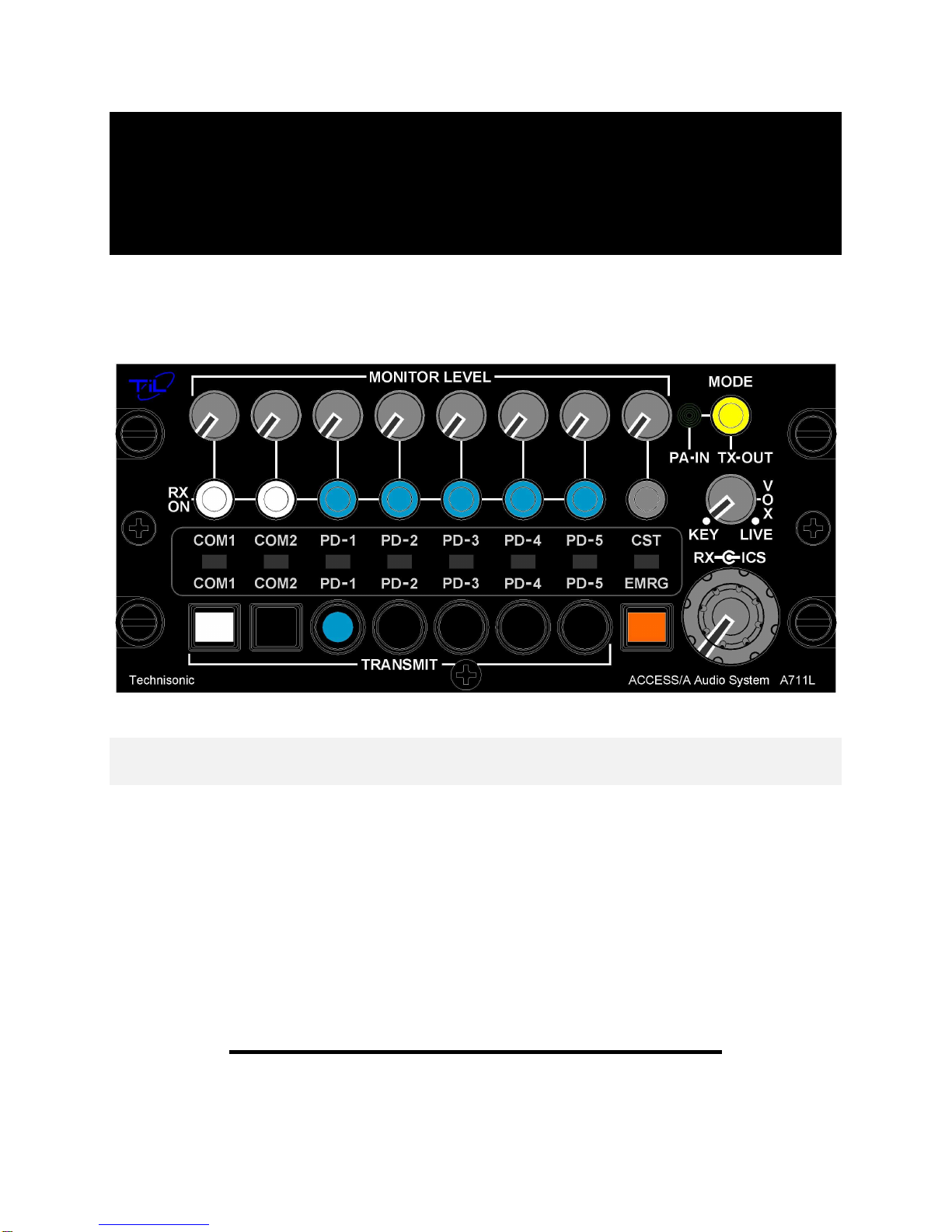
FIGURE 1-2 A711L ACCESS/A AUDIO CONTROLLER - GENERAL VIEW

ACCESS/A A711 L-Series Installation Manual 09RE416
Technisonic Industries Ltd. Copyright 1996, 1997, 2010, 2011 BY TiL ALL RIGHTS RESERVED Page 1-4
1.5 TECHNICAL SUMMARY
A summary of the relevant electrical, operational, mechanical and physical characteristics of the
control panels are given in Table 1-1, General Specifications.
TABLE 1-1 A711 L-Series GENERAL SPECIFICATIONS
MODEL A711L-Series - ACCESS/A Audio Controller:
PHYSICAL CHARACTERISTICS:
Width (max.)...........................................................................................................................5.75 inches
Height (max.)........................................................................................................................2.625 inches
Depth......................................................................................................................................6.07 inches
Weight (including alerting) ............................................................................................3.0 lbs. (1.36 Kg)
Mounting ......................................................................................................Standard Dzus, 4 fasteners
POWER SOURCE REQUIREMENTS:
DC Voltage (MIN, TYPICAL, MAX)......................................................................... 20.0V, 28 V, 32.2V
(System performance will be degraded at upper and lower limits)
DC Current.............................................................................. 1 A (6 users @150 Ω, + speaker @8 Ω)
Backlighting Input:
Standard.........................................................................................................28 Vdc @ 200 mA Max.
TECHNICAL CHARACTERISTICS:
Input Impedance (Normal Mode, any RX input).....................................................2K-1.5K Ω(approx.)
Input Impedance (Emergency Mode, Com1-7 RX Inputs)...........................50 Ω+ Headset Z (typical)
Headset Channel Output Impedance............................................... 8 or 80 Ω(depending on settings)
H/S Audio Power Output.....................................................at least 332 mW (primary user) into 150 Ω
with 6 headsets (150 Ωeach) connected.
H/S Audio Power Output.................................................................at least 500 mW (pilot) into 8-20 Ω
H/S Audio Power Output............................................... at least 1500 mW (total) into 6 users @150 Ω
Speaker Power Output.......................................................................................at least 2.5 W into 8 Ω
Audio distortion (Speaker or H/S) ................................less than 2% THD @1kHz at total rated output
Audio Frequency Response (ICS) ................................................ within 3 dB from 300 Hz to 6000 Hz
Audio Frequency Response (Rx & NAV)...................................... within 3 dB from 300 Hz to 3000 Hz
Hum and Noise Level.......................................................................better than -60 dB below 500 mW
Input Muting (when mike is keyed).........................................................................................adjustable
Input to Input isolation..................................................................... better than -70 dB between inputs
Deselected input isolation........................................................................................ better than -65 dB
CST Input/Output Levels....................................100-150mV into 150 Ωtypical for 100mW H/S power
ENVIRONMENTAL:
Temperature (operating) .................................................................................... -45°C to +70°Celsius
Temperature (survival non-operating) ................................................................-55°C to +85°Celsius
Humidity.............................................................................................................. 95% Non-condensing
Shock............................................................................................................................. 12 g (any axis)
Altitude .................................................................................................................................25,000 feet

ACCESS/A A711 L-Series Installation Manual 09RE416
Technisonic Industries Ltd. Copyright 1996, 1997, 2010, 2011 BY TiL ALL RIGHTS RESERVED Page 1-5
1.6 SYSTEM LIMITATIONS
A summary of the relevant system limitations is given below.
1.6.1 Power Limitations
With Standard Set-up, which consists of six headsets connected, a power output of not less than
332 mW is delivered per headset (as represented by 150 ohms) provided that the Direct Alert
Input is terminated in not less than 600 ohms and that nominal input voltages are applied
at the applicable channel inputs. Nominal microphone input: 100 mV
rms
; Nominal
Communications/Navigational Input: 5.5 V
rms
.
1.6.2 Frequency Response Limitations
In accordance with the provisions made in RTCA/DO-214 Sections 2.8.1 and 1.5.1 the
communications transmit out and receiver channels (communications and navigational) possess
an effective bandwidth of 300 Hz--3000 Hz with a maximum amplitude variation of 3 dB within the
frequency range.
1.6.3 Crosstalk Limitations
To ensure that the crosstalk specifications are in accordance with the applicable sections of DO-
214, it is essential that 1) manufacturer’s maximum microphone input voltage of -4.7 dBu not
be exceeded in order to avoid jeopardising input to microphone output crosstalk results,
particularly at the low frequency end, 2) in the instance where only two access units are daisy
chained via their ICS tie-lines, a resistor of not greater than 600 ohms must be maintained
across the ICS tie-line in order to avoid jeopardising station to station crosstalk results in Rx
mode at the high frequency end.
The phenomenon of music appearing at the headset of the Second Station Panel (SSP or unit at
which the crosstalk is measured) for station to station crosstalk considerations is a limitation of the
A711L and for which crosstalk at high frequencies (6000 Hz and greater) can fall below 65 dB of
attenuation. However music for most intents and purposes may be considered an optional feature,
which may be turned off without a negative impact on the essential functioning of the access units.
Further, valid station to station crosstalk measurements were quoted in respect of a half power
level at the headset at the First Station Panel (FSP or unit from which the crosstalk originates) as
opposed to a half power level at the speaker output of the FSP because it is envisioned in the
latter scenario that the substantial speaker level (which will also necessitate very large signal
levels at the FSP headset) will have an impact on the listener at the SSP whether a crosstalk
signal appears at the SSP listener’s headset or not.
When multiple transceivers are selected for simulcast operation, they are bound together at the
station output, and thus are also bound together for other stations as well, defeating cross-talk
measurements. All measurements are based on single transceiver TX selection.

ACCESS/A A711 L-Series Installation Manual 09RE416
Technisonic Industries Ltd. Copyright 1996, 1997, 2010, 2011 BY TiL ALL RIGHTS RESERVED Page 1-6
1.6.4 Isolation Limitations
When in Pilot Isolation Mode, the pilot microphone for ICS operation is rendered inactive. Consequently,
neither co-pilot nor passengers can receive pilot intercom transmissions while the latter is in Isolation
mode.
1.6.5 Standard Settings Utilised Throughout Testing
Pilot Headset Settings utilized throughout testing was for the standard 150 ohms impedance headset. The
PAL options utilized were applicable to the following configuration: Where Pilot or Co-pilot transmitted on
the UUT ICS communication was possible only in the instance where the signal emanated from other
unit(s) daisy chained to the UUT via the ICS tie-line. In this event the UUT would receive the ICS
transmissions from the other unit(s). It was not possible for the UUT, which transmitted, to export ICS
communication to another unit nor was it possible for intra ICS communication to occur between users
connected to UUT (i.e. Option 1 not implemented).
1.6.6 Transmission Priority
Where Pilot and Co-pilot transmit simultaneously, the Pilot transmissions take precedence over those of
the Co-pilot. Co-pilot transmissions in this case would be rendered inactive.
1.6.7 Induced Signal Susceptibility, RF Susceptibility and RF Emission
The wiring connections called out in the Installation and Operating Instructions, chapter 2, describes shield
terminations for minimum ground loop noise. The test harnesses used for RTCA/DO-160 sections 19, 20,
and 21 – Induced Signal Susceptibility, RF Susceptibility, and Emission of RF Energy respectively - used
shield terminations at both ends of the cable. Should RF susceptibility pose a problem in a particular
installation the installer may wish to try terminating shields at both ends of the cable, further, if this does
not produce satisfactory results then double shielding may be required.

ACCESS/A A711 L-Series Installation & Operating Instructions 09RE416
Technisonic Industries ltd. Copyright 1996, 1997, 2010, 2011 BY TiL ALL RIGHTS RESERVED Page 2-1
SECTION 2
INSTALLATION INSTRUCTIONS
2.1 GENERAL
This section contains information and instructions for the correct installation of the A711 L-Series,
ACCESS/A Audio Controllers. For convenience they are referred to as A711L in the manual.
Make certain that the unit is correctly operating in accordance with the equipment user's
requirements and manufacturer’s specifications, prior to releasing the equipment for service.
2.2 EQUIPMENT PACKING LOG
Unpack the equipment and check for any damage that may have occurred during transit. Save
the original shipping container for returns due to damage or warranty claims. Check that each
item on the packing slip has been shipped in the container. Verify that the equipment's
backlighting configuration is the same as that required.
IMPORTANT! There are ferrite beads on component leads which can produce
IMPORTANT! There are ferrite beads on component leads which can produce IMPORTANT! There are ferrite beads on component leads which can produce
IMPORTANT! There are ferrite beads on component leads which can produce
a muted rattle when the box is shaken, T IS IS NORMAL, DO NOT BE
a muted rattle when the box is shaken, T IS IS NORMAL, DO NOT BE a muted rattle when the box is shaken, T IS IS NORMAL, DO NOT BE
a muted rattle when the box is shaken, T IS IS NORMAL, DO NOT BE
ALARMED.
ALARMED. ALARMED.
ALARMED.
2.3 WIRING REQUIREMENTS
Airframe wiring should be single conductor in accordance with MIL-W-22759 or multi-conductor in
accordance with MIL-C-27500 or Raychem 44 (81044) or 55 single or multi-conductor and
shielded wire. Heat shrink solder sleeves (such as Raychem or equivalent) should be utilized for
shield termination.
All Microphone audio input and output line connections should be made with 2 conductor/twisted
pair shielded cables as illustrated. Receiver audio input lines should also be 2 conductor twisted
pair shielded cables. The power and ground lines should be a minimum of #22 AWG (#20
preferred). Keying and all audio lines may be #24 AWG or larger.
CAUTIONS:
DO NOT bundle any low level audio lines with RF coaxial cables, 60 Hz or 400Hz AC
inverter, motor, pump or blower wiring, which can cause noise coupling between the various
systems, especially during RF transmission or pump/blower mechanical operation. Maintain as
much distance as possible from these types of wire bundles.
Note that there is really no effective field-installable shielding for magnetic coupling (which
occurs at high currents), and the only suitable prevention for this type of interference is distance
between the interfering lines. Shielded wiring is effective only for electrostatic coupling, or voltage
driven interference.

ACCESS/A A711 L-Series Installation & Operating Instructions 09RE416
Technisonic Industries ltd. Copyright 1996, 1997, 2010, 2011 BY TiL ALL RIGHTS RESERVED Page 2-2
2.4 ACCESS/A AUDIO PANEL INSTALLATION
The A711L ACCESS/A Audio Controls are designed to be Dzus mounted and should be installed
in conjunction with an IN-A711L installation connector kit. See Figure 2-1 for an outline drawing
of the units with dimensions, to facilitate the installation.
CABLE CLEARANCE:
Allow at least 2.5” of additional rear clearance for mating connectors and hoods (side routing),
or 3.0” (back routing). Cables should be long enough to permit the unit to be removed from the
panel, and the connectors to be easily disengaged. DO NOT dress or strap the mating cables so
that front removal is impossible, or the unit cannot be removed for service or adjustment in the
field.
ALERT OPERATION:
3 Tone alerting can be supplied with this unit from the factory. Tone frequency and cycle rate, as
well as # 3 alert on-time can be adjusted at the rear of the unit. Field installation of the tone option
must be done at a fully equipped service bench, and requires a system functional test & re-
certification.
PANEL MODIFICATIONS:
Modified panel legends, panel lighting and NVG compatibility, or optional functions are
also possible; please see the price list for a full summary of options and part numbers. Overlays
and legends may be easily changed at low cost in the field with no special tools or service facilities
required.
SHIELD GROUNDS:
Convenient shield ground connections are provided at each connector for the indicated input
signal shield drains, and will give the shortest possible return for these lines. These shield lines
should be daisy chained together, and a single wire from each cable brought out to the designated
connector pin.
INTERNAL OPTIONS:
All configurable and variable options of the A711L (pilot H/S impedance, muting logic, included
speaker audio lines, etc.) can be set or changed simply by altering internal jumpers, but these
changes require opening the unit for access to the required connections.
DRAWINGS:
A full ACCESS/A (mono) system installation example is given in the multi-page sections of Figure
2-x. These installation and mechanical drawings are available as AutoCAD files (“DWG”/R12
format, Windows Metafile “WMF” or “DXF” format) free of charge to authorized TiL dealers and
completion centres.
WIRING CONCEPT OVERVIEW:
Do NOT connect un-needed radio wiring or alerting triggers to any control, even though it
can theoretically operate that radio, as increased cross-talk and possible accidental operation will
result. For good spares support, you may want to have all controls the same, but operationally it
rarely makes sense in the airframe for everyone to have every signal or radio access. Un-
terminated signal inputs pre-wired as spares may become a serious noise source, and are not
recommended. You can run spare wiring, but do not connect it to the A711L until used.
ACCESS/A A711 L-Series Installation & Operating Instructions 09RE416
Technisonic Industries ltd. Copyright 1996, 1997, 2010, 2011 BY TiL ALL RIGHTS RESERVED Page 2-3
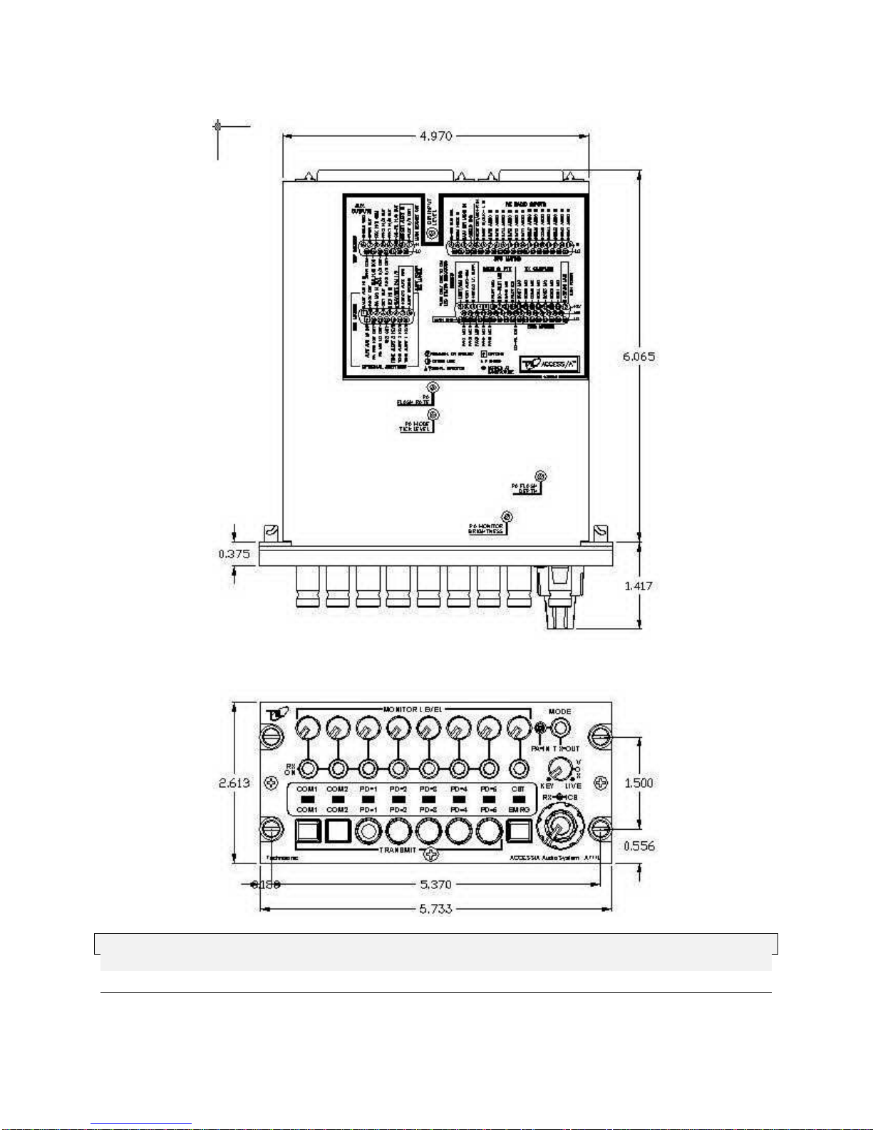
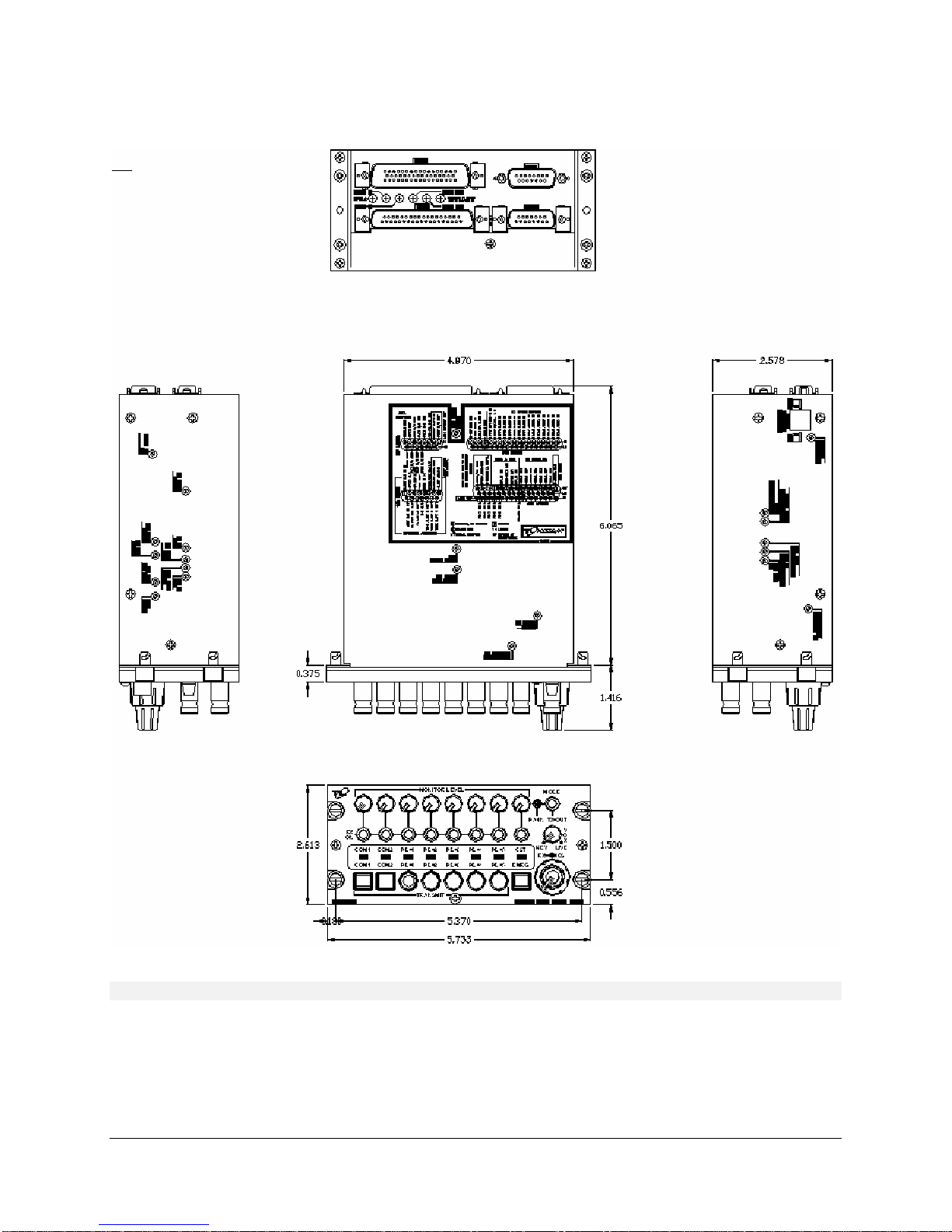
FIGURE 2-1 Outline Drawing for Model A711L ACCESS/A Audio Controller
ACCESS/A A711 L-Series Installation & Operating Instructions 09RE416
Technisonic Industries ltd. Copyright 1996, 1997, 2010, 2011 BY TiL ALL RIGHTS RESERVED Page 2-4
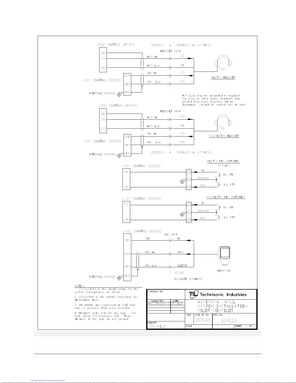
Figure 2-2 PILOT/CO-PILOT WIRING
ACCESS/A A711 L-Series Installation & Operating Instructions 09RE416
Technisonic Industries ltd. Copyright 1996, 1997, 2010, 2011 BY TiL ALL RIGHTS RESERVED Page 2-5
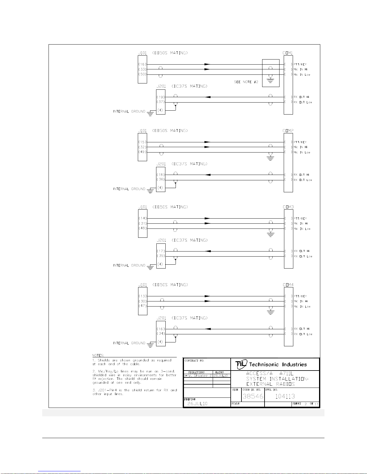
Figure 2-3 COM1-COM4 WIRING

ACCESS/A A711 L-Series Installation & Operating Instructions 09RE416
Technisonic Industries ltd. Copyright 1996, 1997, 2010, 2011 BY TiL ALL RIGHTS RESERVED Page 2-6
Figure 2-4 COM5-NAV1 WIRING
ACCESS/A A711 L-Series Installation & Operating Instructions 09RE416
Technisonic Industries ltd. Copyright 1996, 1997, 2010, 2011 BY TiL ALL RIGHTS RESERVED Page 2-7
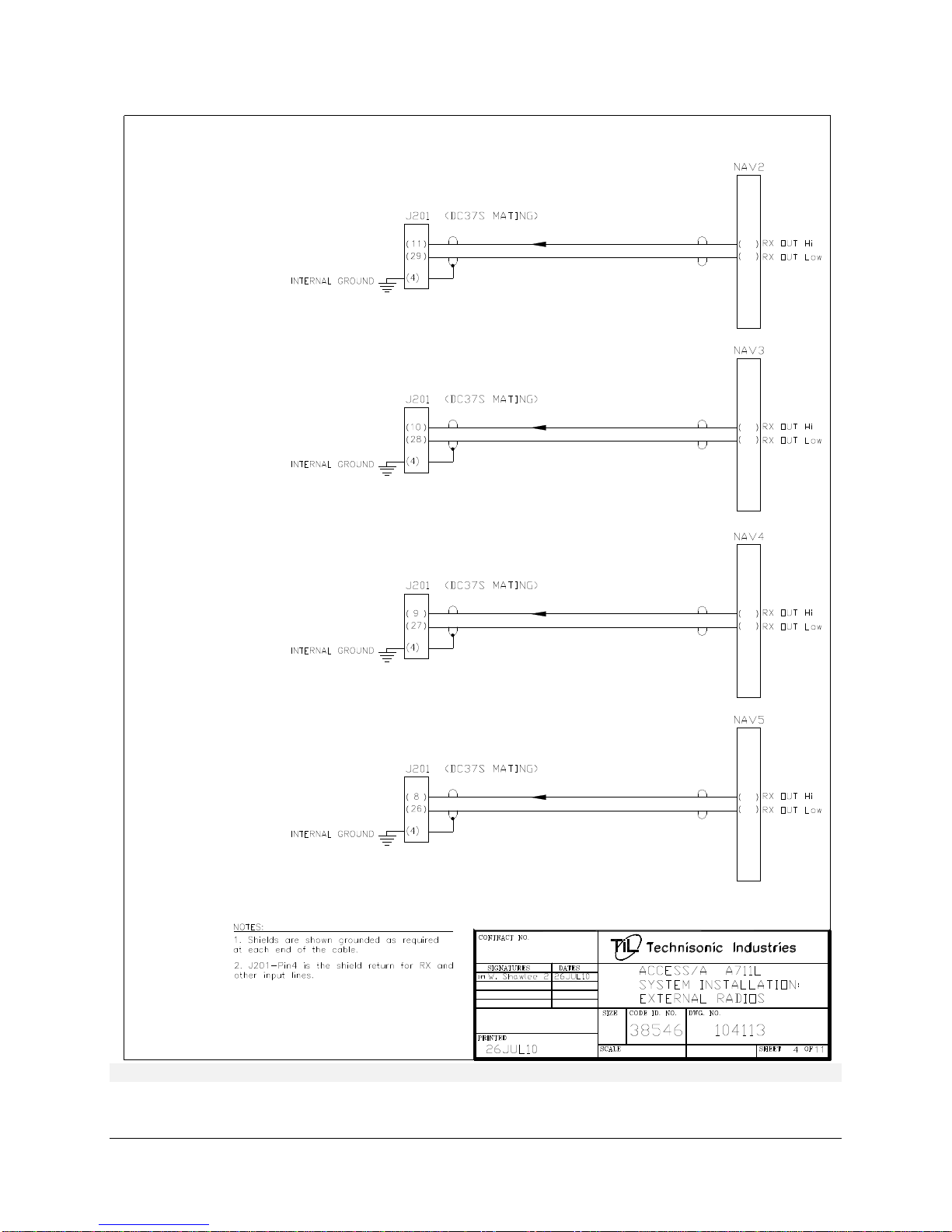
Figure 2-5 NAV2-NAV5 WIRING

ACCESS/A A711 L-Series Installation & Operating Instructions 09RE416
Technisonic Industries ltd. Copyright 1996, 1997, 2010, 2011 BY TiL ALL RIGHTS RESERVED Page 2-8
Figure 2-6 NAV6-NAV8 / CST / MUSIC WIRING

ACCESS/A A711 L-Series Installation & Operating Instructions 09RE416
Technisonic Industries ltd. Copyright 1996, 1997, 2010, 2011 BY TiL ALL RIGHTS RESERVED Page 2-9
Figure 2-7 PASSENGER WIRING
Other manuals for A711 L-Series
2
Table of contents
Other Technisonic Industries Limited Music Mixer manuals


