manuals.online logo
Brands
  1. Home
  2. •
  3. Brands
  4. •
  5. Rolls
  6. •
  7. Music Mixer
  8. •
  9. Rolls RM75 MixMate II User manual

Rolls RM75 MixMate II User manual

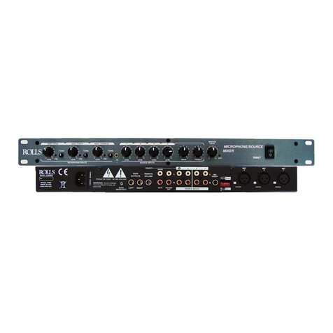
RM75
MixMate II
Mic/Source Mixer
OWNERS MANUAL
LIMITED WARRANTY
This product is warranted to the original consumer purchaser to be free
from defects in materials and workmanship under normal installation, use and
service for a period of one (1) year from the date of purchase as shown on the
purchaserís receipt.
The obligation of Rolls Corporation under this warranty shall be limited
to repair or replacement (at our option), during the warranty period of any part
which proves defective in material or workmanship under normal installation,
use and service, provided the product is returned to Rolls Corporation, TRANS-
PORTATION CHARGES PREPAID. Products returned to us or to an authorized
Service Center must be accompanied by a copy of the purchase receipt. In the
absence of such purchase receipt, the warranty period shall be one (1) year from
the date of manufacture.
This warranty shall be invalid if the product is damaged as a result of
defacement, misuse, abuse, neglect, accident, destruction or alteration of the
serial number, improper electrical voltages or currents, repair, alteration or
maintenance by any person or party other than our own service facility or an
authorized Service Center, or any use violative of instructions furnished by us.
This one-year warranty is in lieu of all expressed warranties, obligations
or liabilities. ANY IMPLIED WARRANTIES, OBLIGATIONS, OR LIABILI-
TIES, INCLUDING BUT NOT LIMITED TO THE IMPLIED WARRANTIES
OF MERCHANTABILITY AND FITNESS FOR A PARTICULAR PURPOSE,
SHALL BE LIMITED IN DURATION TO THE ONE YEAR DURATION OF
THIS WRITTEN LIMITED WARRANTY. Some states do not allow limitations
on how long an implied warranty lasts, so the above limitation may not apply to
you.
IN NO EVENT SHALL WE BE LIABLE FOR ANY SPECIAL, INCI-
DENTAL OR CONSEQUENTIAL DAMAGES FOR BREACH OF THIS OR
ANY OTHER WARRANTY, EXPRESSED OR IMPLIED, WHATSOEVER.
Some states do not allow the exclusion or limitation of special, incidental or
consequential damages so the above limitation or exclusion may not apply to
you. This warranty gives you specific legal rights, and you may also have other
rights which vary from state to state.
ROLLS CORPORATION
SALT LAKE CITY, UTAH
5/02
www.rolls.com
INPUT LEVEL LEVEL LEVEL LEVEL LEVEL LEVEL
MO
N
HDPHONE
OUTPUT
HEADPHONE
LEVEL
1
MAIN
4
3
2
O
NO
CUE
SELECT
RM75
pwr
MIXMATE 2
Microphone / Stereo Source Mixer
INTRODUCTION
Thank your for your purchase of the Rolls RM75 MixMate II Mic / Source Mixer.
The RM75 mixes two microphones with up to four stereo source signals such as
CD players and karaoke machines. The unit is housed in a compact yet sturdy
steel 1U rack chassis.
INSPECTION
1. Unpack and inspect the RM75 box and package.
Your RM75 was carefully packed at the factory in a protective carton. Nonethe-
less, be sure to examine the unit and the carton for any signs of damage that may
have occurred during shipping. If obvious physical damage is noticed, contact the
carrier immediately to make a damage claim. We suggest saving the shipping
carton and packing materials for safely transporting the unit in the future.
2. Please register your new RM75 online at www.rolls.com, or complete the
Warranty Registration Card and return it to the factory.
FEATURES
ï Two Mic Channels
ï Tone controls for each Mic Channel
ï Mic One offers front and rear panel Input jacks
ï +12 VDC Mic Phantom Power
ï Mic Insert for effects processors
ï Four stereo RCA source inputs
ï Bass and Treble controls for Source Inputs
ï Balanced 1/4' TRS Outputs
ï Unbalanced RCA Outputs
ï External PS12 power supply (included) for low noise operation
TABLE OF CONTENTS
Introduction 1
Inspection 1
Features 1
Table of Contents 1
Description
Front Panel 2
Rear Panel 2
Connection 3
Operation 4
Specifications 5
Schematic 6
Warranty Back cover
1
ROLLS CORPORATION
5968 South 350 West
Murray, UT 84107
1
RM75.SCH A
29 March 2002
Title
Size: Document Number:
Date:
Rev:
Sheet of
PARTY MIX RM75
Rb
+12V LEVEL
-12V
-12V
POWER
+12V
-12V
RIGHT IN
LEFT IN
FX INSERT
+12V
-12V
RIGHT IN
LEFT IN
+12V
-12V
RIGHT IN
LEFT IN
+12V
-12V
+12V LEVEL
-12V
-12V
PHAN PWR
PHAN PWR
-12V
SOURCE 3
+12V
D1
1N4001
D2
1N4001
P1
P100K
I
1
G
2
O3
U15
7812
I
2
G1
O3
U16
7912
R107
22K
R106
330
R108
22K
R109
4.7K
R207
22K
P2
P100K
R208
22K
R209
4.7K
13
2
P5A
P100K X2
4 6
5
P5B
P100K X2
1 3
2
P6A
P100K X2
4 6
5P6B
P100K X2
1 3
2
P8A
P100K X2
4 6
5
P8B
P100K X2
R603
22K
R606
22K
J7
PHONE 1/4
R117
100
1 3
2
P4A
P100K X2
4 6
5
P4B
P100K X2
R704
10K
R701
10K
R817
100
C10
1UF
1 2
3
J1
XLR F PC
1 2
3
J2
XLR F PC
C7
503
C12
503
C13
503
C14
503
C15
503
R101
4.99K
R201
4.99K
R401
10K
R404
10K
R501
10K
R504
10K
R601
10K
R604
10K
C105
27PF
C205
27PF
C701
27PF
C702
27PF
R15
4.7K
C11
10UF
R506
22K
R503
22K
R703
22K
R706
22K
6
5
7
8
U1B
4560
2
3
1
4
U1A
4560
2
3
1
4
U2A
4560
6
5
7
8
U2B
4560
2
3
1
4
U8A
4560
6
5
7
8
U8B
4560
2
3
1
4
U9A
4560
6
5
7
8
U9B
4560
6
5
7
8
U5B
4560
2
3
1
4
U5A
4560
6
5
7
8
U4B
4560
2
3
1
4
U4A
4560
C601
27PF
C602 27PF
2
3
1
4
U7A
4560
C501
27PF
C502
27PF
C402
27PF
C401 27PF
C104 27PF
C101
10U
C201
10U
R113
100K
D5
LDSG
R406
22K
R403
22K
R105
330
C103
.001
R102
4.99K
C102
10U
R205
330
C203
.001
R206
330
C202
10U
R202
4.99K
R807
100
R808
47K
2
3
1
4
U10A
4560
R818
47K
6
5
7
8
U10B
4560
C9
1000UF
C8
1000UF
BASS
TREBLE
RIGHT
BASS
TREBLE
LEFT
+12V
-12V
13
2
P10A
P100K X2
46
5
P10B
P100K X2
13
2
P11A
P100K X2
46
5
P11B
P100K X2
6
5
7
8
U11B
4560
2
3
1
4
U11A
4560
J10
PHONE 1/4
J4
PHONE 1/4
R809
33K
R810
22K
R811
33K
R813
33K
R814
1M
R815
10K
R816
10K
R6
22K
R1
22K
R3
51
R5
51
R819
33K
R820
22K
R821
33K
R824 1M
R823
33K
R825
10K
R826
10K
R9
51
R10
51
C3
10U
C6
10U
C806
220PF
C808
220PF
C807 .047
C805 .047
R812
33K
R822 33K
+12V
+12V
2
3
1
4
U12A
4560
6
5
7
8
U12B
4560
R2
22K
R7
22K
C1
27PF
C4
27PF
1
2
3
J8
PCRCAX2
R8
1K
R4
1K
R111
4.7K R112
100K
R211
4.7K
R212
100K
R110
4.7K
R210
4.7K
P7
P100K
P12
P100K
C106
.1
C206
.1
C107
.01
C207
.01
6
5
7
8
U7B
4560
C204
27PF
+12V
-12V
+12V +12V -12V -12V
+12V
AUX OUT/
HDPHN
46
5
P3B
P100K X2
J9
PHONE 1/4
2
31
4
U3A
4556
6
5
7
8
U3B
4556
13
2
P3A
P100K X2
C16
47U
R12
10
R14
10
C17
47U
R13
10K
R11
10K
SOURCE 1
SOURCE 2
SOURCE 4
1
2
3
SW2A
DPDT
2
3
1
J11
JAPDC
R405
47K
R502
47K
R505
47K
R605
47K
R602
47K
R705
47K
R702
47K
R402
47K
1 2
3
J3
XLR F PC
2
H1B
HD6
1
H1A
HD6
4
H1D
HD6
5
H1E
HD6
3
H1C
HD6
PHAN PWR
6
H1F
HD6
2
3
5
6
14
SW1A
SW DP5TROT
7
8
10
11
129
SW1B
SW DP5TROT
1
3
J6A
RCAX4
2
3
J6B
RCAX4
4
6
J6C
RCAX4
5
6
J6D
RCAX4
4
6
J5C
RCAX4
5
6
J5D
RCAX4
2
3
J5B
RCAX4
1
3
J5A
RCAX4
C2
27PF
+12V
-12V
+12V
C? 27PF
C?
25PF C?
25PF
C? 27PF
LINE OUT
SCHEMATIC
1 6
DESCRIPTION
FRONT PANEL
INPUT LEVEL LEVEL LEVEL LEVEL LEVEL LEVEL
HDPHONE
OUTPUT
HEADPHONE
LEVEL
1
MAIN
4
3
2
MONO
CUE
SELECT
RM75
pwr
MIXMATE
2
Microphone / Stereo Source Mixer
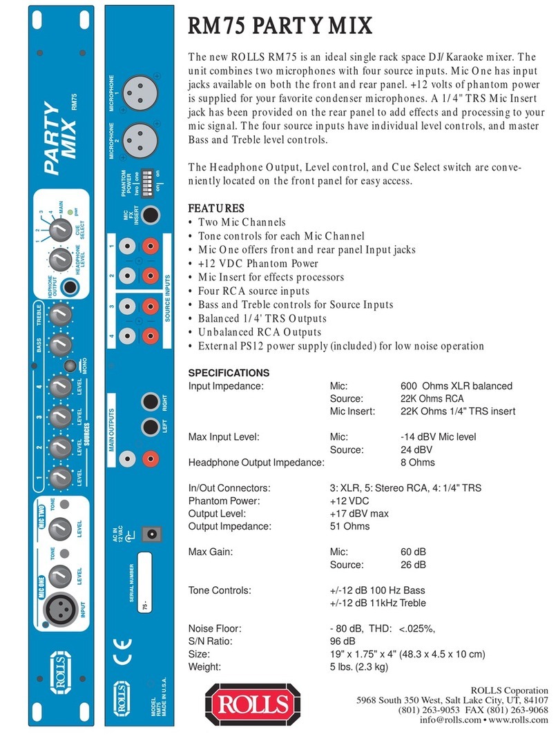
INPUT: Balanced XLR jack for connection to a dynamic or condenser microphone.
This jack parallels the Channel 1 Microphone Input on the rear panel.
NOTE: The following two descriptions are for Mic 1 and Mic 2.
LEVEL: Adjusts the amount of signal from the Microphone Input channel to the
Main Outputs.
TONE: Adjusts the relative frequency components of the Mic signal. Turning this
control clockwise from the center (detented) position decreases the high frequen-
cies. Turning the control counter-clockwise from center decreases the low fre-
quencies.
SOURCE LEVEL CONTROLS 1 - 4: Adjust the amount of signal from the indi-
cated Source channel to the Main Outputs.
BASS: Varies the amount of the low frequency portion (150 Hz) of the Source
signals.
TREBLE: Varies the amount of the high frequency portion (10 kHz) of the Source
signals.
HEADPHONE OUTPUT: 1/4î Tip-Ring-Sleeve jack for connection to any standard
pair of audio headphones.
HEADPHONE LEVEL: Adjusts the amount of signal to the Headphone Output.
CUE SELECT: Selects a Source signal, or the Main Output signal to be sent to
the Headphone Output.
REAR PANEL
AC IN
12 VAC
MODEL
RM75
MADE IN U.S.A.
75 -
RECORD OUT
MICROPHONE
2
MICROPHONE
1
MIC
FX
INSERT
PHANTOM
POWER
two one
on on
AC INPUT: Connects to the included Rolls PS12 AC adapter.
LINE OUTPUTS
RCA: Unbalanced output jacks
1/4î: Tip-Ring-Sleeve balanced ouput jacks
SOURCE INPUTS: Unbalanced RCA input jacks.
FX INSERT: 1/4î Tip-Ring-Sleeve jack for connection to an insert plug (see
diagram) and to an effects processor. Allows for effects to be added to the micro-
phone signals.
PHANTOM POWER: Header pins for applying 12VDC phantom power to the
indicated microphone.
MICROPHONE INPUTS 1 and 2: Balanced XLR jacks for connecting to dynamic
or condenser microphones.
SPECIFICATIONS
Input Impedance: Mic: 600 Ohms XLR balanced
Source:
22K Ohms RCA
Mic Insert: 22K Ohms 1/4" TRS insert
Max Input Level: Mic: -14 dBV Mic level
Source: 24 dBV
Headphone Output Impedance: >8 Ohms
In/Out Connectors: 3: XLR, 5: Stereo RCA, 4: 1/4" TRS
Phantom Power: +12 VDC
Output Level: +17 dBV max
Output Impedance: 51 Ohms
Max Gain: Mic: 60 dB
Source: 26 dB
Tone Controls: +/-12 dB 100 Hz Bass
+/-12 dB 11kHz Treble
Noise Floor: - 80 dB, THD: <.025%,
S/N Ratio: 96 dB
Size: 19" x 1.75" x 4" (48.3 x 4.5 x 10 cm)
Weight: 5 lbs. (2.3 kg)
5 2
CONNECTION
Ensure the RM75 is securely mounted in a 19î rack. Connect the PS12 power
supply to an AC outlet (preferrably a power strip with master switch). If the unit is
to be used in a permanent install, connect all sources and microphones to the
desired channels on the rear panel. Remember which signal sources are con-
nected to which Source Inputs.
For use in mobile DJ/Karaoke rigs, the microphone should be connected to the
front panel Microphone Input so it may be easily removed when the mobile rig is
packed.
Shown below is a possible connection example for the RM75.
OPERATION
Make sure all audio connections are in place, and power is applied to all pieces of
equipment necessary for operation, ie; speakers, power amplifiers, microphones
etc.
Normally, only one source signal is heard at a time along with a microphone
signal. Therefore, begin with all Levels completely counter-clockwise (off). Keep
the Headphone Level control low and, using the Cue Select switch, select which
Source signal you wish to hear. There will be nothing heard from the Main Outputs
until you increase the level of a Source or Mic channel. You may now ìcueî or
prepare the Source selection for playing. Set the Headphone Level for a comfort-
able amount. Increase the Source Level of the ìcuedî channel, and begin playing
the selection.
You may now select a different channel by moving the Cue Select switch to
another Source Channel, and ìcueî another song.
__________________________________________________________________
USING THE MIC EFFECTS INSERT
In order to add effects to the microphone signal, an insert cable is needed. The Tip
of the plug acts as the Send, the Ring is the Return.
Connect the insert cableís TRS end to the Mic FX Insert jack on the rear of the
RM75. Connect the Tip connection to your effects processorís Input jack, and the
Ring connection to the Output of the effects processor. The RM75 effects insert is
mono, so if the effects processor is stereo - choose a Mono output. You may need
to refer to your effects processor owners manual for more information about
operating it in mono.
Make sure a microphone is properly connected to the RM75 and the unit is on.
Speak into the microphone and adjust the levels of your effects processor for the
desired process and level of effect.
THIS DEVICE COMPLIES WITH FCC
RADIATION LIMITS AT TIME OF MANUFACTURE
CAUTION: To reduce the risk of
electric shock, do not remove lid. No user
serviceable parts inside. Refer servicing
to qualified service personnel.
WARNING: To reduce the risk of
electric shock or fire, do not expose
this device to rain or moisture.
FREQ SELECT
9kHz 10kHz
RISQUE DE CHOC - NE PAS ENLEVER
FM ANT
75 Ω
AM LOOP
300 Ω
MODEL RS79
120 VAC
50/60 Hz 15 VA
MADE IN THE U.S.A.
SERIAL NUMBER
79-
LEFT OUTPUT
RIGHT OUTPUT
AC IN
12 VAC
MODEL
RM75
MADE IN U.S.A.
75 -
MICROPHONE
2
MICROPHONE
1
MIC
FX
INSERT
PHANTOM
POWER
two one
on on
MAIN OUTPUTS
INPUT
BAL
BA
Channel B Channel A
INPUT
THRU
BA
CAUTION
MINIMUM LOAD IMPEDANCE
2 OHMS PER CHANNEL
4 OHM BRIDGE
FUSE
15A/120V
- BRIDGE MONO +
POWER AMPLIFIER
+
-
+
2-
3
1234
BA
14
23
LOW
CUT FILTER
ON=30Hz
OFF=50Hz
LOW
CUT FILTER
ON=30Hz
OFF=50Hz
1
GROUND
LIFT
AMP MODE
STEREO BRIDGE
Rolls
PS12
12VAC
600mA
THIS DEVICE COMPLIES WITH FCC
RADIATION LIMITS AT TIME OF MANUFACTURE
CAUTION: To reduce the risk of
electric shock, do not remove lid. No user
serviceable parts inside. Refer servicing
to qualified service personnel.
WARNING: To reduce the risk of
electric shock or fire, do not expose
this device to rain or moisture. RISQUE DE CHOC - NE PAS ENLEVER
120 VAC
50/60 Hz 15 VA
MADE IN THE U.S.A.
LEFT OUTPUT
RIGHT OUTPUT
CD PLAYER
KARAOKE MACHINE
TO SPEAKERS
TO SPEAKERS
3 4
Other Rolls Music Mixer manuals

Rolls PM350 User manual

Rolls

Rolls PM350 User manual

Rolls RM64 User manual

Rolls

Rolls RM64 User manual

Rolls MX902 User manual

Rolls

Rolls MX902 User manual

Rolls MX310 MorMic User manual

Rolls

Rolls MX310 MorMic User manual

Rolls MX28 User manual

Rolls

Rolls MX28 User manual

Rolls RM203X User manual

Rolls

Rolls RM203X User manual

Rolls RM68 User manual

Rolls

Rolls RM68 User manual

Rolls RM316 User manual

Rolls

Rolls RM316 User manual

Rolls RM65 HEXMIX User manual

Rolls

Rolls RM65 HEXMIX User manual

Rolls Rm203x User manual

Rolls

Rolls Rm203x User manual

Rolls MixMax RM81 User manual

Rolls

Rolls MixMax RM81 User manual

Rolls RM65B HexMix User manual

Rolls

Rolls RM65B HexMix User manual

Rolls RM83T User manual

Rolls

Rolls RM83T User manual

Rolls MX44 Pro User manual

Rolls

Rolls MX44 Pro User manual

Rolls RM65b HEXMIX User manual

Rolls

Rolls RM65b HEXMIX User manual

Rolls RM64 User manual

Rolls

Rolls RM64 User manual

Rolls RM68 - SCHEMA Quick start guide

Rolls

Rolls RM68 - SCHEMA Quick start guide

Rolls RM74 User manual

Rolls

Rolls RM74 User manual

Rolls RM65 6 x 4 User manual

Rolls

Rolls RM65 6 x 4 User manual

Rolls RM64 User manual

Rolls

Rolls RM64 User manual

Rolls RM81 MIXMAX User manual

Rolls

Rolls RM81 MIXMAX User manual

Rolls MX34c LiveMix User manual

Rolls

Rolls MX34c LiveMix User manual

Rolls MiniMix MX22s User manual

Rolls

Rolls MiniMix MX22s User manual

Rolls Field Mixer MX442 User manual

Rolls

Rolls Field Mixer MX442 User manual

Popular Music Mixer manuals by other brands

Phonic PM801 user manual

Phonic

Phonic PM801 user manual

Choice Select MX -8S operating manual

Choice Select

Choice Select MX -8S operating manual

Behringer B-Control Deejay BCD3000 quick start guide

Behringer

Behringer B-Control Deejay BCD3000 quick start guide

DigiDesign D-Control Guide

DigiDesign

DigiDesign D-Control Guide

Peavey MP 400 operating guide

Peavey

Peavey MP 400 operating guide

Vestax MX-1 Operational manual

Vestax

Vestax MX-1 Operational manual

Power Dynamics PDV120S instruction manual

Power Dynamics

Power Dynamics PDV120S instruction manual

Radio Shack 32-2058 user guide

Radio Shack

Radio Shack 32-2058 user guide

Galaxy Audio JIB/MM owner's manual

Galaxy Audio

Galaxy Audio JIB/MM owner's manual

Monacor PA-4040MPX instruction manual

Monacor

Monacor PA-4040MPX instruction manual

Crest Audio X-Eight HS Specifications

Crest Audio

Crest Audio X-Eight HS Specifications

Yamaha M2500-24 Service manual

Yamaha

Yamaha M2500-24 Service manual

Gemini MDJ-1000 Operation guide

Gemini

Gemini MDJ-1000 Operation guide

Clear One CONVERGE SR 1212 datasheet

Clear One

Clear One CONVERGE SR 1212 datasheet

sky-tec STM-3020B user manual

sky-tec

sky-tec STM-3020B user manual

CyberView H117 user manual

CyberView

CyberView H117 user manual

SM Pro Audio PM8 operating manual

SM Pro Audio

SM Pro Audio PM8 operating manual

IMG STAGE LINE PMX-122FX instruction manual

IMG STAGE LINE

IMG STAGE LINE PMX-122FX instruction manual

manuals.online logo
manuals.online logoBrands
  • About & Mission
  • Contact us
  • Privacy Policy
  • Terms and Conditions

Copyright 2025 Manuals.Online. All Rights Reserved.